Triple conversion receivers and even quadruple conversion receivers appeared in the 1960s. These receivers had schemes like the one shown in Fig. 1 and went so far as to bring the last conversion to as low as 85 kHz or even 50 kHz, in order to achieve good selectivity economically with L/C filters.
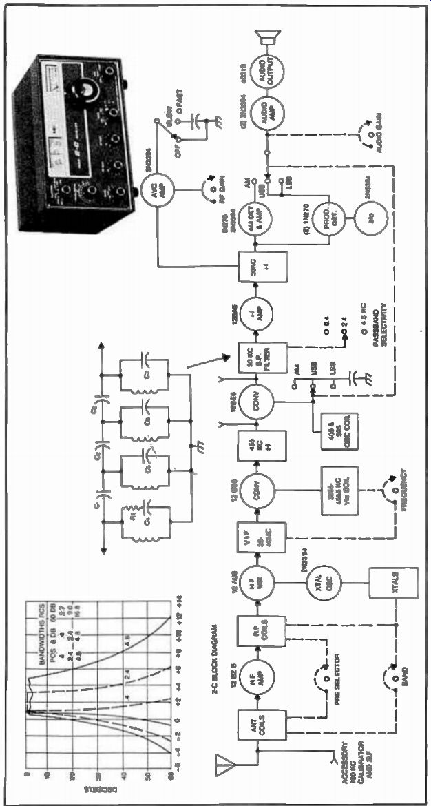
Fig. 1. Drake 2-C receiver block diagram and selectivity.
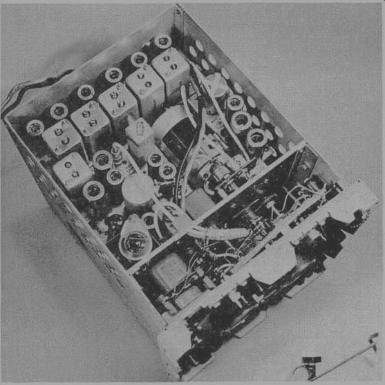
Fig. 2.
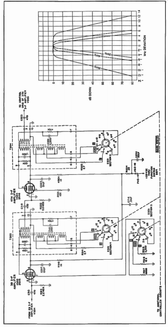
Fig. 3.
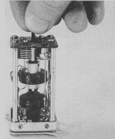
Fig. 4. An ARC-5 i-f transformer. Selectivity was achieved at 85 kHz
by varying the distance between two windings as shown.
The Drake 2C was a famous example of such a receiver, and it used a triple-conversion scheme with the first i-f between 3.5 and 4 MHz, the second i-f of 455 kHz, and a third i-f of 50 kHz. For economical reasons, the selectivity was not achieved at 455 kHz but at 50 kHz with the help of L/C circuits. It consisted of four tuned circuits of very high Q that were capacitively coupled in cascade as shown in Fig. 1. A characteristic of such coupled circuits is that the bandwidth or selectivity is largely dependent on the degree of coupling, being greatest with light coupling. Thus, by switching in different coupling capacitors, the overall selectivity could be varied accordingly. As the coupling was increased, however, a dip in the pass-band tended to appear. R1 was then inserted (This tended to lower the element Q on the first resonator, thereby changing the pass-band.) or varied as needed to provide a flatter response in the pass-band at the broader selectivity portions. Also, as the coupling was increased, the response curve spread out from both sides of the initial resonant frequency.
The set-up was, therefore, also arranged so that resonating capacitances were altered for the various selectivity positions, in order that the low frequency side of the response curve in each case remained at a fixed point.
Another receiver that used L/C coupling to achieve selectivity, was the Collins R-392 (Fig. 2). The 392 had variable bandwidth in the second i-f at 455 kHz by using a rather interesting electromechanical approach (Fig. 3). By mechanically varying the position of the coils in the i-f transformers, different degrees of coupling and, therefore, selectivities were achieved. To illustrate this, we took an i-f transformer out of a radio that uses the same approach. Fig. 4 shows how it works.
The R-392 used some of the most complex electro-mechanical implementation ever used to this date. While still considered to be a good receiver, even by today's standards, it remains a symbol of the past.