Loudspeaker Impedance Varies with Frequency
The performance of a loudspeaker is greatly affected by its impedance characteristic. There is far more to the matter of loudspeaker impedance than simply that of its 8- or 16-ohm nominal specification.
The impedance of a loudspeaker is not a constant. It varies considerably with frequency. The impedance of a speaker at its low frequency resonant point may be four to five times its rated impedance At high frequencies it may again be more than four to five times the rated impedance. Since the power a loudspeaker can accept from an amplifier is dependent upon the speaker impedance, it is apparent that the output of the loudspeaker will be greatly affected by the manner in which its impedance varies from point to point throughout its operating range.
Rated Impedance Usually Taken in 400-hz Area
The rated impedance of a loudspeaker is actually the value taken at one small narrow band of the overall impedance curve. Figure 5-1 illustrates an impedance curve of a typical 12-inch speaker as taken in free air; the speaker is unrestricted by any baffled conditions. The standard method of rating the impedance of a loudspeaker, according to RETMA standards, is to choose the value of the impedance at the bottom of the trough immediately following the first peak of the impedance characteristic. It so happens that in the conventional 15-, 12-, and 8 inch speakers, this trough falls in the general neighborhood of 400 hz.
Therefore, the rated impedance of the speaker usually holds at this general mid-low frequency. However, the impedance characteristic may convey a great quantity of information, in addition to the rated impedance, that will be extremely helpful in understanding the performance characteristics of a loudspeaker.
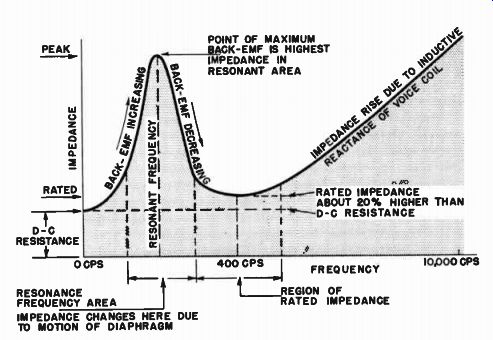
Fig. 5-1. The impedance characteristic of a loudspeaker will determine
the power that the speaker will accept at low and at high frequencies
in relation to the power at its rated frequency and the damping required.
Actually, the rated impedance does tell us what the matching impedance of the amplifier should be to get the best power match to the speaker at approximately 400 hz. At the low-mid frequency range, an 8-ohm speaker should be connected to the 8-ohm output tap of an amplifier in order to obtain the best performance from the combination. The rated impedance of the loudspeaker is also a means of determining what power is fed to the loudspeaker. Thus, when 8 volts is applied across an 8-ohm speaker, 8 watts will be delivered to the speaker. These are some of the simple facts conveyed by the rated impedance of the loudspeaker. However, we must approach these facts with considerable caution, realizing that they apply only for a relatively narrow frequency band (specifically, the low-middle and middle frequency ranges).
Impedance Varies Greatly at Resonance
The greatest variation in impedance of a speaker is in the vicinity of the resonant frequency. All mechanical vibrating systems have a natural resonance. At this natural resonance, they vibrate most freely.
The degree to which any mechanical body vibrates at its natural frequency is dependent upon the mass of the body, the springiness by which the mass is held, and the mechanical resistance to motion within the system itself or to resistance externally applied.
If a weight were hung by a spring suspended from the ceiling, and the weight were pulled down and then released, it would bob up and down at some rate, or frequency, which would be determined by the actual weight of the mass and the stiffness of the spring. If the spring were a very loose one, the weight would bob up and down slowly over large distances. The system would then have a low natural resonance, and a large "excursion," or amplitude of motion. If the spring were a very stiff one, the weight would bob up and down rapidly over small distances. The system would now have a high natural resonance and small excursion. On the other hand, if the spring were kept un changed and the weight were reduced, the resonance would rise and the excursion would decrease. Therefore, for mechanically vibrating bodies, the heavier the mass, the lower the resonant frequency; the stiffer the suspension, the higher the resonant frequency. In general, then, if we have a large ratio of stiffness to mass, we will have a high resonant frequency. If we have a low ratio of stiffness to mass, we will have a low resonant system.
These factors are determining elements in the natural resonance of the loudspeakers, and they help to explain why larger speakers have lower resonant frequencies and smaller speakers higher resonant frequencies. In a 15-inch woofer, the cone is relatively heavy because of its size. In order for it to be able to move over the considerable distances necessary for good low frequency reproduction, the cone must be rather loosely suspended in relation to its weight. The woofer diaphragm system, therefore, has a small ratio of stiffness to mass, and has a low natural resonant frequency. Smaller speakers intended for higher frequency operation have smaller and lighter diaphragms, but these are more tightly held in relation to their mass. There is a high ratio of stiffness to mass, and consequently small speakers and tweeters have a high resonant frequency. The important consideration of this resonance characteristic is how it affects the impedance and operation of the loudspeaker.
Impedance is a highly descriptive term. It obviously refers to the property of blocking or stopping something. In electrical terminology, impedance of an item is essentially a measure of how the flow of alternating or changing current is restricted through it. A high impedance permits only small values of current to flow and, conversely, a low impedance allows large values of current to flow. There fore, let us examine the highly variable impedance characteristic of the loudspeaker as it pertains both to the electrical circuit with which the loudspeaker has to cooperate and to the way in which the performance of the loudspeaker itself is affected by its mechanical resonance.
High Back-emf at Resonance Blocks Current: High Impedance
The diaphragm of a loudspeaker is attached to a voice coil balanced in the gap of the magnetic circuit of the loudspeaker. Now let us apply a signal to the loudspeaker and examine how it behaves as we change the frequency of the signal. (See Fig. 5-1.) If we start at one extreme, say "zero" frequency, we are applying direct current to the loud speaker voice coil. Under the influence of this zero frequency (or direct) current, the voice coil is displaced from its equilibrium position and remains displaced without subsequent motion. Under this condition the voice coil appears as a simple resistance, and its "impedance" is therefore only the actual direct current resistance of the voice coil. Now, as we leave the point of zero frequency, and begin to cycle the current, vibration of the diaphragm will take place. As soon as this happens, the voice coil, which now moves in the magnetic gap, acts as a generator of electricity and produces the well known "back-emf." This is the electromotive force generated by the voice coil while in motion in its surrounding magnetic field. According to basic electrical laws, this electromotive force is generated in opposition to the applied voltage. If this internally induced voltage bucks the actual external voltage applied to the voice coil, it is obvious that less current can get to the speaker. Its impedance is thus higher than at the rest condition.
As the voice coil vibrates more energetically over larger and larger distances, and at a faster and faster rate, the back-emf induced in the voice coil rises higher and higher, effectively causing a further increase in the impedance of the loudspeaker. The maximum excursion of the vibrating diaphragm occurs at the frequency of its natural resonance, i.e., where it is most free to vibrate. At this resonant frequency, where the diaphragm is under-going maximum excursion, the back-emf is largest and the impedance highest. As the applied frequency continues to increase, the point of resonance is passed and the diaphragm excursion begins to grow smaller. There is less back-emf produced in the coil, and the impedance begins to drop.
Due to the fact that in the area of resonance the change in apparent electrical impedance of the speaker is almost wholly due to its motion, this impedance is usually referred to as its motional impedance. Since the effective motion of the voice coil is dependent upon the interaction of the field due to the voice coil current with the strength of the fixed magnetic field, we may expect two results if the weight of the loudspeaker magnet is increased. First, the driving force on the voice coil is increased, causing greater motion of the voice coil. Secondly, the back-emf is greater because of the more violent voice coil motion in a denser magnetic field. We should therefore expect the resonant frequency impedance of the loudspeaker with a heavier magnetic structure to be higher in value than for the same loudspeaker with a light magnet. The effect is illustrated in Fig. 5-2. This impedance variation with magnet weight is very important as it affects damping, efficiency, and load regulation upon the amplifier, and will be covered in later sections of this sectionafter we have finished analyzing the impedance curve as a whole.
Trough (Rated) Impedance is Lowest A-C Impedance
As the input frequency to the loudspeaker is now further increased the resonance area is left behind and the motion of the coil in the magnetic gap becomes gradually limited in excursion while the back-emf is correspondingly reduced. The reduction of the back-emf results in a drop from the high resonance impedance value down to the trough, or rated impedance. (Refer back to Fig. 5-1). This trough impedance is higher than the original d-c resistance of the coil, for now there is added to the coil's d-c resistance the inductive reactance of the coil carrying the alternating current. The total impedance of the voice coil to the flow of alternating current through it is the (vector) sum of its d-c resistance and its inductive reactance, which is a function of the frequency.
In the trough area then the impedance drops to a value close to the d-c resistance of the coil, but somewhat raised by the inductive reactance of the coil at this trough area frequency. In this area the actual impedance may be between 15 and 20 percent higher than the d-c resistance. It is therefore easy to ascertain the rated impedance of a loudspeaker by measuring its d-c resistance with a simple ohmmeter and then increasing this measured value by 15 to 20 percent. Thus a speaker whose d-c resistance measures 6 1/2 ohms probably has a rated impedance of 8 ohms.
Voice Coil Inductance Raises High Frequency Impedance
After this trough area has been passed, the increasing frequency of the voltage applied to the voice coil causes it to exhibit higher and higher inductive reactance, which effectively causes the impedance characteristic of the loudspeaker to rise at a fairly steady rate. Thus, at low frequencies, the effective impedance of the speaker (and its result ant electrical performance) is greatly dependent upon its physical motion; while, at the higher frequencies, its effective impedance (and its resultant electrical performance) is greatly dependent upon the voice coil winding characteristics.
IMPEDANGE AREA WHERE HIGHER IMPEDANCE OF CONE WITH HEAVY MAGNET WILL PREVENT POWER FROM BEING ABSORBED BY SPEAKER IMPEDANCE CURVE OF CONE WITH HEAVY MAGNET SAME CONE WITH LIGHT MAGNET IN THIS AREA, IMPEDANCES ARE EQUAL, AND SPEAKERS WILL TAKE SAME POWER. THE ONE WITH THE MORE POWERFUL MAGNET WILL PRODUCE MORE ACOUSTIC POWER FREQUENCY
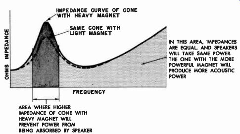
Fig. 5-2. A heavier magnet raises the resonant frequency impedance causing
power input discrimination in this area unless the combined speaker enclosure
and amplifier system are properly damped.
Speaker Most Efficient at Resonance
However, before we are in a position to analyze the true meaning of the loudspeaker impedance characteristic and to see how the overall acoustic response of the loudspeaker is affected by its preponderantly motional impedance at the resonant area and its preponderantly inductive impedance at the higher frequencies, we must examine one further property of vibrating systems that affects the freedom with which the system vibrates. This factor is the mechanical resistance of the system.
When a system goes into resonant vibration, the frequency at which it vibrates is such that the inertia effects of the dead weight of the mass and liveness of the spring are balanced out and the system wants to continue to vibrate indefinitely. If there were no internal resistance in the system, and no external resistance applied to it, the system would vibrate forever even after the driving force had been removed. However, all mechanical vibrating systems have inherent mechanical resistances which limit their motion. Yet, no matter what the magnitude of the restraining resistance may be, the vibrating system still works most efficiently at the resonant point, because of the self cancellation between the mass of the system and the springiness of its suspension. At resonance the driving force has to overcome only the internal resistance of the system. Therefore, at the resonant frequency the vibrating system is working at top efficiency. Consequently, in the case of a loudspeaker, where we look for optimum low frequency efficiency, we look for low resonant frequency.
Power Input is Minimum at Resonance
We must not me misled by the fact that because the loudspeaker is most efficient at its resonant frequency it is being operated upon most efficiently by the amplifier. In fact, because of its high impedance at resonance, the loudspeaker may suffer severe power input discrimination unless proper baffling and damping considerations are followed.
If the loudspeaker is connected to an amplifier of a constant-voltage type (such as one having much negative feedback), no matter what the amplifier sees as a load impedance, it will always deliver the same voltage to the load, regardless of its impedance. If the resonant impedance of a loudspeaker is 32 ohms, while its trough (or rated impedance) at 400 cycles is 8 ohms, the loudspeaker will receive only one-quarter of the power at the resonant point that it would receive at 400 cycles from a constant voltage amplifier. Thus, despite the fact that the loudspeaker may be most efficient at its resonant point, in combination with its amplifier its power input efficiency is low.
Now the question may be asked whether maximum acoustic efficiency and minimum power input at the resonant point do not cancel each other. In a general manner, the increased efficiency of the speaker at resonance is balanced by the decreased power getting into the circuit of the speaker. The exact manner in which this balance would take place would be a function of the manner in which the amplifier output voltage changed with the changing load presented to it by the changing impedance of the speaker, and also of the efficiency characteristic con tour of the speaker.
Figure 5-3 shows the efficiency characteristic of a certain direct radiator loudspeaker and its corresponding impedance curve. Let us make some sample calculations of expected power output for this loud speaker when connected to an amplifier that maintains perfectly constant voltage. The impedance at resonance is 24.7 ohms, its efficiency at resonance is 6.5 percent. If we assume that the amplifier voltage is 10 volts, the power input to the speaker is (E2/Z) or 100/24.7, or 4.05 watts. If the speaker efficiency (at resonance) is 6.5 percent the acoustic power output will be 4.05 x .065, which equals .263 watt. At 400 hz, where the impedance is 5.5 ohms, the input power will be 100/5.5, which is 18.2 watts input. Note that this power input of 18.2 watts at 400 hz is considerably greater than the 4.05 watts input at the resonant point. If we now apply the 400-hz efficiency factor (which is 1.2 percent) to this value, we get 18.2 X .012, which equals .218 watt. Thus, although the power into the speaker at 400 hz is almost 4 1 / 2 times the power input at resonance, their different efficiencies
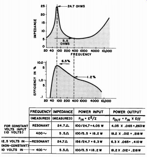
Fig. 5-3. Although the high impedance at resonance discriminates against power
getting into the speaker, the higher efficiency at resonance may over come
this input power deficiency.
... virtually balanced out the system to produce nearly equal acoustic output - .263 watt compared to .218 watt.
Now let us apply the same problem to an amplifier whose voltage regulation is not perfect. As an example, let us allow the voltage of the amplifier to go up by 25 percent as we go from the rated low load impedance to the much less heavily loaded condition (24.7 ohms). Thus, if the voltage across the speaker impedance of 5.5 ohms at 400 hz were 10 volts, the voltage across the speaker at the resonant point would be 25 percent higher, or 12.5 volts. Now the power into the speaker at resonance would be 12.5 2/ 24.7, which is 6.3 watts. Applying the efficiency factor of 6.5 percent for the resonance frequency, we get 6.3 X .065, which is .410 watt. In this case the different power input characteristics of the speaker are not balanced out by the respective efficiencies -- .410 watt output at resonance compared to .218 watt at 400 hz.
Damping Equalizes Power Input to Speaker
From the illustrated numerical example, it can be readily seen that more electrical power would be delivered to the voice coil of the speaker if the resonant impedance peak were subdued, and that the extent of this increase in input power would be dependent upon the characteristic regulation of the amplifier and the actual degree to which the resonant impedance peak were to be lowered. However, whether this increase in power input would result in a subsequent increase in acoustic output depends upon the manner in which the resonant peak is minimized and upon the baffling of the speaker. Thus, for instance, a speaker may be designed with a large value of mechanical resistance in the moving system, which will tend to restrict both the excursion and the impedance peak. However, much of the electrical power de livered to the speaker under these conditions of high mechanical resistance is wasted in overcoming this resistance. There is thus no essential gain in acoustic output. However, if the speaker is damped through proper enclosure loading, in which useful acoustic output is obtained, as in a true horn baffle, the diaphragm moves very little at resonance, though it still delivers full power at high efficiency.
The reason why the diaphragm moves only small distances under a horn load stems from the fact that the large horn mouth is actually the vibrating surface that communicates with the air, and it is quite large in comparison to the actual diaphragm. Hence, in a horn load, the mouth of the horn may be many times greater than the actual piston diameter. For instance, in a typical horn loaded enclosure, the mouth may be at least 14 square feet in area. By horn transformer action, which is discussed in more detail in Part 2, it will be seen that this large "diaphragm of air" at the mouth of the horn is transformed into a high acoustic impedance at the throat of the horn by the "squeezing in" action of the horn as one looks down the horn toward the throat area. The diaphragm sees this high impedance of the air load of the horn and is consequently restricted from moving over any great distances. It is, as we might say, highly damped by the acoustic load of the horn. But because this acoustic load is one that actually is effective in radiating acoustic power into the surrounding air, the subdued peak is then representative of useful loading upon the diaphragm; that is, the resonance of the diaphragm is subdued due to the load, and represents useful power consumption. Similarly, but to a lesser degree, in the case of the bass-reflex enclosure and speaker, the final impedance characteristic peaks are considerably lower than the original free air impedance peak because of the acoustic load imparted to the speaker by the baffle and the air which is driven by the baffle conditions. The impedance peaks are not only lowered but actually distributed and spread out over a larger area. This condition is again representative of, and due to, the radiation load as seen by the system, and thus represents good acoustic efficiency, although not of the same order as that of the horn-loaded speaker.
In both of these cases, then, the damping of the impedance peak is due to useful acoustic power being radiated without power being wasted in mechanical resistance. Thus it will be seen that the increased power into the loudspeaker, due to resonance damping, is converted into useful acoustic power to a degree governed by the nature of the damping.
Acoustic radiation damping will convert input power to acoustic output.
Mechanical or acoustic loss methods of damping will only convert input power to heat.
In the case of the horn, additional power gets into the speaker (either for constant power or for constant voltage) at the resonant frequency, due to the extreme damping of the diaphragm motion because of the horn, and this increased input power to the voice coil results in smooth power input to the speaker at resonance, with increased acoustic output at high levels. However, this does not represent a peaked acoustic output but rather a smooth acoustic output because the input power to the speaker is smoothed out and the horn itself represents a smooth acoustic load. Over the broad resonance area, there will be an increase in acoustic output due to the acoustic loading and improved power input in contrast to the one specific peak of efficient acoustic output in the case of the unloaded speaker. Similarly, in the case of the bass-reflex enclosure, the speaker diaphragm, although not as beneficially loaded, still exhibits lowered resonance peaks on either side of the normal free-air resonance. The power input to the loudspeaker is thus smoothed out over a considerably broader area than that originally accepted by the free-air resonance peak of the speaker.
One cannot categorically state, however, that there will necessarily be improved acoustic output because of the damping of the speaker, unless one has the complete data concerning the extent of acoustic damping and the manner in which it is applied, and the regulation of the amplifier. Hence one might find that, in a horn-loaded system operated from a perfectly constant voltage amplifier, the power input to the speaker might not necessarily be as high in the resonant areas as the power input to a speaker in a bass-reflex enclosure fed from a constant power source.
To summarize this problem, then, in order to obtain high efficiency it is beneficial to damp the impedance peak of the speaker for purposes of allowing more power to be admitted to the loudspeaker. The means of damping should be that of good acoustic loading and not resistive mechanical loading or acoustic loss loading. By damping the impedance peak of the speaker more uniform power input and more uniform power output are obtained in sharp contrast to the peaked output of the undamped speaker; and the regulation of the amplifier is markedly effective in determining the smoothness of power input to the speaker.
Damping Improves Transient Response
Efficient damping of the resonant peak, however, does more than equalize the power input to the speaker. It also improves the transient response of the loudspeaker. The moving system of a loudspeaker has a certain amount of inertia. It takes time for a force to overcome the inertia of the moving system when the latter is standing still. When a suddenly applied electrical signal is fed to the voice coil, the force of the interaction between the field it produces and the gap flux tends to move the voice coil. It takes a certain time for the inertia of the voice coil and its diaphragm to be overcome before the system can begin to move. Accordingly, there is some delay between the instant when the signal is applied and the time when the diaphragm responds to the signal. This time delay between the action and the reaction constitutes a form of transient distortion.
The delay time may be reduced by increasing the magnetic field, for then the driving force on the voice coil becomes greater. The inertia of the moving system will be overcome faster, and consequently there will be a shorter delay between the originating signal and the resultant motion of the diaphragm. It is much like the case of two or three people pushing a stalled car into motion slowly compared to a sudden jar applied by a tow truck. Thus a strong magnetic field improves the "attack" time of a note. However, once started, some notes stop sharply, some slowly. Whatever the rate at which the tone decays, the loudspeaker should stop producing that note when the signal stops, or the loudspeaker will continue to "ring" or "hang over" after the signal has stopped.
Here again, for the decaying note there will be faster reaction to the signal if the magnetic field is stronger. Once a system is moving, it will continue to move unless it is stopped. Inertia is just as effective for a body in motion as it is for a body at rest. In the loudspeaker from which the signal has suddenly been removed, there is no voltage driving the voice coil. It immediately stops acting as a motor. However, due to the inertia of the moving diaphragm, the system continues to vibrate.
The loudspeaker voice coil now acts as a pure generator, whereas before it had generated a "back-emf." The current generated in the voice coil now flows back into the low impedance output transformer of the amplifier. This constitutes a closed circuit for the loudspeaker voice coil and interaction is now set up between the voice coil generated current and the magnetic field, bringing the coil to a stop by means of magnetic braking effects. Thus, if the magnet is weak, there will be a small degree of magnetic braking and the diaphragm will continue to vibrate for some time after the signal has been removed. This condition is usually termed "hangover." If the magnetic field is strong, there will be heavy braking action and the diaphragm will come to an immediate stop, reducing hangover. Thus it is seen that by the use of a heavy magnet field, both attack and decay time response of a loud speaker are considerably improved, which means that the loudspeaker transient response is improved.
Inspection of the two impedance curves in Fig. 5-2 will show that, despite the fact that the resonant impedance peak of the heavy magnet is higher in peak amplitude than that of the weaker magnet, the two impedance curves come together at the middle and at the high frequencies. This means that for a given voltage applied to both speakers the heavy magnet speaker will allow less current to enter the voice coil in the resonant area than will the weaker magnet structure. There- fore, in this resonant area, the speaker with the heavy magnet will receive less power input than the speaker with the lighter magnet (al though the former will be more efficient than the latter). However, at the middle and the high frequency ranges, where the impedance curves are governed more by the electrical characteristics of the voice coil than by the motion of the voice coil, these impedance curves, being alike, will result in equal power getting into both voice coils. If equal power gets into both speakers, the one with the more powerful magnet will deliver more acoustic power output. There fore, we want to maintain all the benefits of a powerful magnet at those middle and upper frequency areas, but in addition find some means to overcome the high impedance peak at the resonance area so that the same power input efficiency may be obtained for the heavy-magnet speaker at resonance as is obtained at other frequencies.
Critical Damping Provides Optimum Transient Response
There are several means of reducing this high impedance peak. A great deal may be accomplished with the aid of the enclosure into which the loudspeaker is to work. Also, much can be done through the amplifier that drives the speaker. Whatever the means employed, however, the end effect of any compensation is optimum when the combined circuit of the loudspeaker system and the amplifier has a Q of unity.
This means that the effective resistance in the total electro-acoustical circuit as related to the mass reactance is such that there is just enough resistance in the circuit to prevent the speaker from running wild and overshooting on a signal pulse. (See Fig. 5-4.) When the system is underdamped (running wild and overshooting), the Q is high; when the circuit is overdamped (held way down), the Q is low; when the circuit is operating just right (optimum output without overshoot), the circuit is "critically damped" and the Q is unity.
The amount of damping necessary will, in part, be determined by the extent to which the resonant impedance peak of the speaker rises above the rated impedance of the speaker. This is just one of the important facts evident from the impedance curve. That curve also presents an overall picture of the efficiency of the loudspeaker over the entire frequency spectrum. It tells us the degree to which the input power at low frequencies would be restricted because of the high motional impedance; it also tells us how the input power to the loud- speaker is restricted at the high frequencies due to the rising inductive reactance characteristic. We might, therefore, say that the impedance curve of a loudspeaker is the clue to its overall performance.
Amplifier Regulation Also Determines Power Input
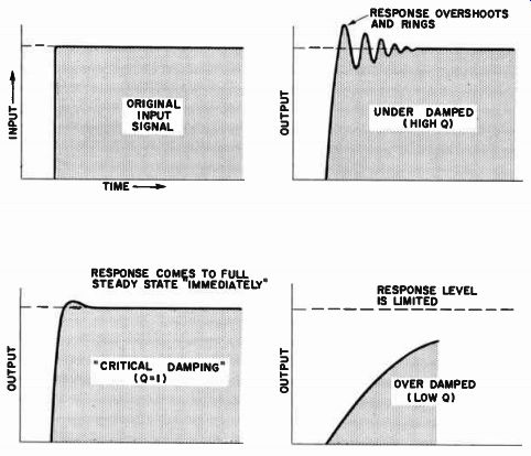
Fig. 5-4. Proper damping will make the loudspeaker respond to a signal
without excessive overshoot, and without loss of output.
In the light of the above discussions, it would be worthwhile to discuss in a little more detail the combined effect of this varying impedance curve and the amplifier performance. It was previously seen that constant voltage amplifiers operate in a manner to push the least power into the speaker where the impedance curve is high, as it is at resonance and at the high frequencies. Consequently, there will be comparatively poorer response in these areas. On the other hand, constant voltage amplifiers obtain that particular characteristic by means of large amounts of feedback, which effectively reduces the internal impedance of the amplifier. Reduced internal impedance of the amplifier simply means that there will be improved damping of the loud speaker. The overall resistive component of the combined circuit of the constant voltage amplifier output and the loudspeaker itself will not be so high that it will exceed the value needed for critical damping of the loudspeaker-amplifier combination.
On the other hand, there are amplifiers that may be adjusted to give constant power instead of constant voltage. These amplifiers are sensitive to changes in impedance of the loudspeaker. This means that regardless of how the impedance of the loudspeakers changes, the loud speaker always receives the same amount of power for a given setting of the amplifier volume control. In amplifiers of this sort, however, the internal impedance of the amplifier is not always kept low, and optimum damping is not always obtained.
Amplifier Compensation Only Partly Overcomes Poorer Speaker Efficiency
The question of damping has recently attracted attention from amplifier manufacturers because it is fairly easy to accomplish good damping by electrical means. The introduction of these various damping means into the amplifier may make the combined amplifier-speaker combination sound better. However, we must not let this approach make us lose sight of the fact that, if the loudspeaker itself is inefficient, the system as a whole will not operate to optimum satisfaction. For instance, it is true that there are amplifiers that may take a speaker with a very weak magnet and, through the amplifier's greatly extended variable damping capabilities, produce just the right amount of damping on the speaker to give it good transient response and input power regulation. However, the overall efficiency of the speaker with the weak magnet is so low that the amplifier may have to be turned way up in gain in order to obtain reasonable output. This may result in overdriving the amplifier on high sudden program peaks with resulting distortion. Therefore, despite the fact that the amplifier can take care of certain deficiencies in loudspeakers, it is better policy to start with the best we can obtain in the way of loudspeaker performance and then use the amplifier compensation to supplement the loudspeaker characteristics rather than to replace them.