The previous two sections have discussed in detail the manner of operation of the pure enclosure type baffle and the pure horn type baffle, and it was seen that there were specific advantages and disadvantages to both types. There are many designs of loudspeaker en closures that attempt to combine the features of both these systems into a single structure. This section will deal with the most prevalent examples of these combinations.
Horn Loading of Bass-Reflex Port Improves Port Radiation
The most straightforward (and the newest) variation of the bass reflex enclosure is that in which the port itself is loaded by a small section of horn, as illustrated in Fig. 8-3(C). The addition of this "port horn" accomplishes two beneficial results that improve the over all performance of the bass-reflex enclosure. From the section on the enclosure type baffle, the reader will recall that specific mention was made of the effect of the introduction of a duct type port. Because this duct introduced more inertance into the resonant circuit, it was thereby possible to make the enclosure volume smaller and still maintain the same resonant condition. This situation is, of course, highly desirable where it is the objective to make a cabinet of unobtrusive size. Inspection of the structure shown in Fig. 8-3(C) will reveal that the horn-loaded port is in essence an extension of this principle.
Thus it is apparent that the horn-loaded port enables the formulation of a structure of smaller proportions for equivalent low frequency output.
Besides this function of shrinking cabinet size, the port horn plays an important acoustical part in improving the low frequency radiation that emanates from the port. We have seen from the chart of radiation resistance (Fig. 9-1) that the radiation resistance of a piston for a particular frequency goes up as the size of the piston increases. This characteristic does not necessarily apply only to a physically solid piston. Actually, the mouth of a horn may be considered as a piston, for it is the virtual source of the pulsations of sound. We might call any opening from which sound emerges an infinitely thin and infinitely light membrane, and we may apply to it in all theoretical justice the same laws of radiation physics that apply to an actual physical diaphragm. Thus, the larger we can make the opening from which the sound is to emerge, the better its radiation characteristic will be for a given frequency, especially in the low end.
This is the second advantage of the port horn. It provides better radiation efficiency for the low frequencies coming out of its comparatively large mouth than does the simple port. It is recognized that the horn in this section seems almost too short to be theoretically efficient. However, as often happens, shortcomings in theory may turn out to be blessings in disguise, if properly utilized. Figure 11-1 shows the radiation characteristic of a very short horn (in relation to the theoretical cutoff wavelength of the horn). Because of this shortness and the corresponding comparatively small size of the mouth (even though it is larger than the original port), the radiation characteristic of the horn is quite ragged, as illustrated. If we were to try to utilize this horn for broad band reproduction, it would be entirely useless because of its ragged and irregular nature. However, we are not interested in broad band response from the port horn. We are interested primarily in its output at one very narrow band of frequencies, at the lower resonant peak of the impedance characteristic of the system.
Consequently, we can design this port horn short in length in relation to this low frequency, thereby getting a peaked radiation from the short horn just where we want to reinforce the radiation characteristic.
We have, as it were, turned the tables on the nonresonant horn, and made it resonant for the specific purpose of improving the low frequency radiation over a restricted range, and from an otherwise smaller opening.
Port Improved When Placed in Corner
This sort of horn-loading of the port may be considerably improved if the enclosure is placed so that it is in the corner of the room, as illustrated in Fig. 11-2, Such placement will improve the overall efficiency of the system for low frequencies and provide an actual extension of the port horn by the corner of the room to make the radiation from the port horn even more effective. A more thorough discussion of this placement problem will be given in Part 3, but for the present it is sufficient to say that, when properly designed and properly used, the horn-loaded port may greatly improve the performance of the bass-reflex enclosure. The overall characteristic of this system is a high level of bass performance within moderately small structures with speakers of the direct radiator type that must face directly into the listening space, and for high efficiency woofer en closures in which may be mounted auxiliary tweeter components.
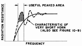
Fig. 11-1. Definite peaked characteristic of short horn and small mouth
compared to wavelength make the horn useful as a high efficiency radiator
over a small desired frequency range as in the horn loading of a port
of a bass-reflex enclosure. ---------- ON RESISTANCE USEFUL PEAKED
AREA N CHARACTERISTIC OF VERY SHORT HORN (ALSO SEE FIGURE 10-9) FREQUENCY
Front Horn on Bass Reflex Improves Middle Frequencies
The variation in the combination type enclosure system opposite to the one just described is shown in Fig. 8-3 (B). In this case, the rear section of the enclosure is an altered bass-reflex unit, while the forward part of the speaker is horn-loaded. Although diagrammatically the horn applied to the front of the speaker may appear to be a short one, it is actually one of fairly decent size acoustically. A horn should not be measured in absolute dimensions, but should be considered in relation to the frequencies it is to transmit. Thus, although a tweeter ...
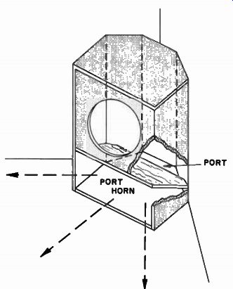
Fig. 11-2. Corner placement for port horn makes horn more effectively
load ed. (After University)
... horn may be small in physical size, in relationship to the actual very short wavelengths of the high frequencies involved, the size of the tweeter horn is considerable. (For example, the wavelength of a 13,500 hz sound signal is only about an inch.) We must, therefore, consider the presently indicated horn in reference to its intended pass band of frequencies.
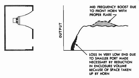
Fig. 11-3. Providing a front midrange horn makes it possible to tilt
the performance curve of a given size of enclosure to enhance the midrange "presence" of
the system where necessary. MID-FREQUENCY BOOST DUE TO FRONT HORN WITH
PROPER FLARE LOSS IN VERY LOW END DUE TO SMALLER PORT MADE NECESSARY BY
REDUCTION IN ENCLOSURE VOLUME BECAUSE OF SPACE TAKEN UP BY HORN
On this basis, we see that a horn 10 inches or more in length would represent sizable dimensions for frequencies of approximately 700 hz and up. Seven hundred hz is equivalent to a wavelength of 20 inches; and the half wavelength horn of 10 inches in length is long enough to support the formation of the wave train down this horn for that frequency and all higher frequencies. By thus loading the forward face of the direct radiator with a horn whose dimensions are comparable to the mid-frequency wavelengths, we increase the middle range efficiency of the system.
As far as low frequencies are concerned, the system acts as a conventional bass-reflex enclosure with the rear of the speaker facing directly into the resonant cavity of the system. For proper low frequency response from the bass-reflex section, the rear of the speaker must utilize the same effective volume as if there were no front horn attached to it. Consequently, the overall size of the enclosure must contain the volume originally required for the desired bass response from the speaker, plus the space taken up by the front horn.
Inasmuch as the front horn adds to the midrange efficiency of reproduction of the speaker, it will be found that this sort of structure is of value where the particular speaker to be used has insufficient middles, or where more middles are desired for increasing the "presence" of the system. It is, therefore, possible to "tilt" the performance curve of the speaker (as shown in Fig. 11-3) by maintaining the same overall volume for the structure as for an ordinary bass-reflex enclosure, and using some of that space for the midrange horn. The reduction of the bass-reflex volume necessitates a smaller port with decreased port radiation efficiency. This results in a small drop of the low frequency response, while the horn raises the mid-frequency response. The characteristic performance is thus made more "projective" with a slight loss at the low end. If, however, space is not a factor to be considered, the bass-reflex section of the cabinet may be enlarged to the optimum volume and port size necessary to give it the proper bass reproduction, and overall performance of the system will then be improved.
It will be apparent that this system is, of course, adaptable to direct radiator loudspeakers. However, there may be some loss of high frequencies at the extreme angles because of the shading effect of the sides of the front horn on the wide angle radiation from the tweeter units that are integral with the recessed main speaker.
Rear Horn on Direct Radiator Provides Additional Low-Frequency Loading
In the next variation of the combination type of enclosure the loudspeaker performs as a simple direct radiator from its forward side with nothing interposed between it and its audience, but the rear of the speaker works into a full low-frequency horn. In this structure, as shown in Fig. 8-3(A), the entire volume of the cabinet is used for the woofer horn, which must be folded to be contained within reasonable proportions. It is obvious that the intent of this type of enclosure is to obtain some of the benefits of woofer horn-loading and retain direct radiation action from the forward side.
These benefits of direct radiator action are completely realizable from the illustrated structure, but there are some compromises in woofer horn performance in comparison with the pure horn system.
Without the compression chamber, we have no way of compensating the speaker for the relatively heavy air load mass that the horn focuses onto the rear of the diaphragm. Thus, the diaphragm is working into a light load on its front side and a relatively heavy load on its rear side.
(See previous section.) Because of this, undesirable nonlinearity may be introduced into the low frequency reproduction. Furthermore, the absence of the "stiffness reactance" (which the compression chamber would normally ensure) means that the horn "mass reactance" at the low frequency is not balanced out, and therefore, optimum utilization of acoustic pressure is not made by this open horn in the low frequency regions. However, despite the shortcomings of this rear horn, it does provide good low frequency response with reasonably good efficiency.
Note that in this sort of construction there is actually an acoustical crossover between the woofer horn and the speaker that allows only the low frequencies to be transmitted from the horn and allows the middles and high frequencies to radiate from the front of the speaker ( in addition to the lows). This acoustical crossover action is an important part of the characteristic performance of these combination systems, and is treated in detail in Section 13.
Acoustic Labyrinth is Tuned Rear Column
A combination type of enclosure, which enjoys some popularity, is the folded tuned column enclosure or Acoustical Labyrinth' as illustrated in Figs. 8-3(D) and 11-4. Although it may look like the rear horn-loaded structure, the rear section is not a horn but a long tube of fairly uniform cross-section. The term labyrinth arises from the fact that the tube, being folded to preserve space, presents the appearance of a maze or labyrinth. Its convolute twisted appearance, however, has no bearing upon the manner in which it works. Essentially, the purpose of the tubular column that loads the back of the speaker is to present to the speaker a definitely tuned "pipe" much like an organ pipe.
All tubes are resonant devices. The frequency of their resonance depends upon their length. Blow across the neck of a bottle and it will respond with a certain tone. Partly fill the bottle with water and the pitch will rise because the air column has been shortened. The trombonist lowers the pitch of his instrument by pulling out the slide and making the instrument longer, and the trumpeter changes the pitch of his instrument by closing off different sections of the length of his instrument with the valves. In the pipe organ the different tones are elicited from tubes of different length corresponding to the frequency desired. Thus, if we want to reinforce a particular frequency, we must couple to the source of sound a pipe cut to the right length to correspond to this frequency.
Tuned Column Impedance Varies with Frequency
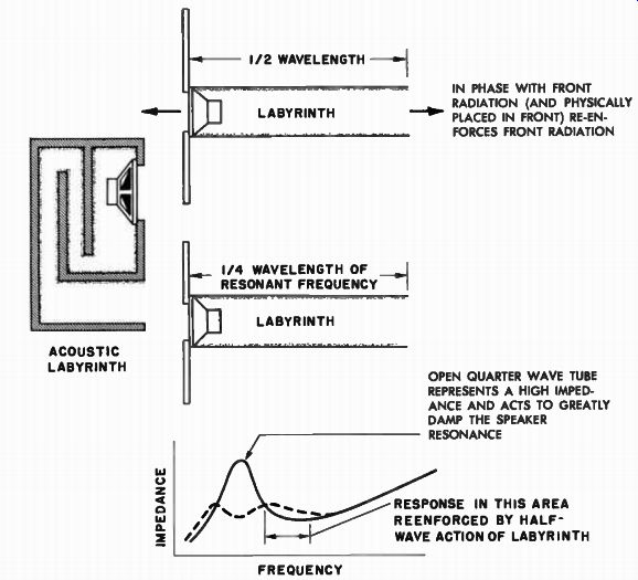
Fig. 11-4. The acoustic labyrinth. Rear tube highly damps the resonant
peak of speaker, re-enforces area above resonance, producing smooth
low frequency response. (After Stromberg-Carlson) ----------- IN PHASE
WITH FRONT RADIATION (AND PHYSICALLY PLACED IN FRONT) RE-ENFORCES FRONT
RADIATION OPEN QUARTER WAVE TUBE REPRESENTS A HIGH IMPEDANCE AND ACTS
TO GREATLY DAMP THE SPEAKER RESONANCE RESPONSE IN THIS AREA REENFORCED
BY HALF-WAVE ACTION OF LABYRINTH.
This is essentially the action of the folded tube in the acoustic labyrinth. The length of the resonating tube is chosen to reduce the resonant frequency impedance peak of the speaker and reinforce other frequencies close to an octave below and above the resonant frequency of the speaker. This is similar in effect to the bass-reflex action. Figure 11-4 illustrates how this action is accomplished. If the length of the tube is such that it corresponds to a half wavelength of the sound transmitted through it, at the instant the sound appears at the open end of the tube, it is already a half wavelength behind the speaker pulse of that instant. However, since the back of the cone radiation started out-of-phase with the forward radiation of the cone, the net result is that the sound coming out of the end of the tube is now completely in phase with the front and reinforcement of the front radiation takes place. Thus, at the particular frequency where the tube is one-half wavelength long the effect of the tube is to cause reinforcement.
Now, as we go down in frequency (longer wavelength), we come to a frequency (an octave lower) where the tube is only one-quarter the length of the sound wavelength. When this happens, the open one-quarter wavelength tube presents a high impedance to the diaphragm, and the motion of the diaphragm becomes severely damped.
If this "quarter wavelength" is made to correspond to the resonance frequency of the speaker, the tube acts as an anti-resonant device at the resonance of the speaker. Thus the acoustic labyrinth damps the resonant peak of the speaker while reinforcing those frequencies an octave above the resonant frequency. The fact that the tube is tuned to the resonant frequency and puts a severe damping restraint upon the diaphragm motion produces a severe depression in the resonance characteristic of the speaker directly at the point of its maximum value. This leaves two humps of response on either side of the frequency where the anti-resonance effect of the tube is most effective.
The end result is a resonance characteristic as shown in Fig. 11-4 that looks very similar to the curve obtained from a bass-reflex structure.
The effect of the tuned tube of the labyrinth is then to provide good damping characteristics and extended flat low frequency response. Due to the large cross-section of the mouth of the tube, a greater value of radiation resistance is seen by the labyrinth, reflected in improved damping of the system.
One feature of the acoustic labyrinth is that its resonant tube is lined with highly absorbent material, which adds a resistive characteristic to the selectivity of the tube, causing smoother resonant and anti resonant action than if the tube were not so treated. The sound absorbing material within the tube also serves to decrease the high frequency transmission of sound through it.
The acoustic labyrinth structure is obviously suitable for use with loudspeakers that are required to act as direct radiators from the front, and where, at the same time, bass reinforcement is required at the rear of the speaker. An important factor that must be considered, as far as such a system is concerned, is that in the normal course of usage, and over a period of time, the self-resonant point of a speaker may gradually go down because of the gradual loosening of the suspension of the speaker. When this happens, the labyrinth goes out of tune with the speaker and its effectiveness is somewhat decreased (unless this factor was originally taken into account). This same action is, of course, true of all speaker systems to a varying degree. In the bass-reflex enclosure for instance, the cabinet is also tuned to the resonance of the speaker, and should the resonance change with constant use the cabinet adjustment will also suffer. however, in this case, the reflex action covers quite a broad band at the low end and the detuning effect is not seriously notable. In any event, one may readily change the port area to compensate for this resonance change.
In the case of the horn loudspeaker system, changes in the re sonant frequency of the speaker may also result in a shift in the low frequency performance because of the point upon the horn transmission characteristic where the speaker is placed. If the speaker resonance drops too far, its point of maximum efficiency has left the most favor able area of the radiation characteristic of the horn and the system suffers.
The Combination Enclosure Performance Depends Upon the Combined Features
It is important to point out that these structures, being combinations, may naturally be combined to varying degrees to get different performance characteristics. Thus, in one case we had a front horn and a rear reflex chamber; in another case we had a full rear horn and direct forward radiation, and the choice determined the performance.
It meant increased presence with moderate lows in the former case and increased lows with moderate presence in the latter case. It stands to reason that there is an almost infinite variety of such combinations between one extreme and the other. However, whatever the design, it will represent a system in which compromises are made in one area to obtain benefits in other areas. The design must be closely integrated with the particular speaker to be used, for obviously we would not want to increase the presence of a speaker already rich in middles and deficient in lows. Nor would we want to extract the absolute maximum of low frequency output from a speaker by subjecting it to a legitimate horn load, if our system were already unbalanced in favor of the low end. These are the facts that make it difficult to prescribe the "best" of these various combinations.