Radiation Resistance of Loudspeaker Determines Power Output
The term circuitry is just as applicable to acoustic devices as it is to electrical components; a loudspeaker requires an acoustic load, just as an electrical circuit requires an electrical load, if power is to be developed. The purpose of any baffle is to provide the speaker with the proper load, into which it operates to produce acoustic power output.
However, acoustic circuitry is somewhat more complex than electrical circuitry because the sound waves developed are not as easily confined and channeled as are electrical currents flowing through wired circuits. On the other hand, there is a very close analogy between sound wave propagation and radio wave propagation. The student of physics will find the relationships that describe the propagation of these two types of energy to be very nearly identical, and one term common to both fields is "radiation resistance." The radiation resistance of an antenna determines how much radio power will be transmitted (or received). Similarly, the radiation resistance of a loudspeaker determines its power transmitting capabilities.
Radiation resistance is not a constant factor. It changes with the frequency of the power being transmitted and with the dimension of the device that does the transmitting. Common everyday illustrations of this fact are seen on almost every rooftop today. Television antennas are cut to size for a particular band of frequencies. Where optimum reception for all channels is desired, we may find a separate antenna cut to exact size to match the frequency of transmission of each channel.
However, where economy of installation requires that only one antenna be used for all channels, it is probable that some channels will not come in as well as others. This occurs because they are not matched in impedance (mainly radiation resistance) for the frequencies of those channels which are not well received. This mismatch reduces the signal sensitivity, and may set up energy reflection, which the layman commonly recognizes as "ghosts" on his television screen. To briefly summarize, all wave transmitting devices, electrical and acoustical, have a definite radiation resistance, which determines the power output, and which is a function of the frequency being transmitted, the method of coupling, and the size of the transmitting "antenna." In the case of the acoustic "antenna" (the loudspeaker), the general curve that describes its radiation resistance is shown in Fig. 9-1.
Note that the radiation resistance of the loudspeaker increases from some very low value to a value of approximately 42 acoustic ohms (per square centimeter). Now, the specific acoustic impedance of air is also approximately 42 ohms. This means that maximum power will be transferred to the air from the loudspeaker when the loudspeaker approaches an impedance of 42 ohms per square centimeter, for then the "genera tor" impedance will be equal to the load impedance. This principle is as true in acoustics as it is in electrical systems.
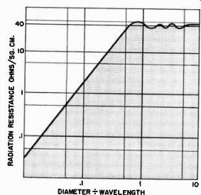
Fig. 9-1. The acoustic power developed by a loudspeaker is a function
of its radiation resistance, which increases as the ratio of the diameter
of the piston divided by the wavelength of operation.
Radiation Resistance Varies with Size of Speaker and Frequency
Inspection of Fig. 9-1 will show that the radiation resistance of the loudspeaker drops quite rapidly as the ratio of the diameter of the loudspeaker to the wavelength of the sound decreases. Although this may appear somewhat complex, let us examine it in terms of simple principles, for once it is understood the entire subject of baffles and enclosures will be more readily appreciated. Briefly, the curve means that if we keep the wavelength (or frequency) unchanged and let the diameter of the loudspeaker decrease, the ratio of the diameter to the wavelength decreases, and the radiation resistance per unit area of the loudspeaker drops. The power transmitted for that particular frequency drops correspondingly. If the speaker size remained unchanged, however, and instead the wavelength increased (frequency decreased), the ratio of the diameter of the speaker to the wavelength would also decrease, again there would be a drop in the radiation resistance of the speaker, and less power would be radiated.
This explains the two commonly experienced phenomena occurring in low frequency reproduction from loudspeakers. First, for a given low frequency, the smaller the loudspeaker the poorer will be the power output. Secondly, for a given size of loudspeaker, the low frequency output will drop off as the frequency goes down. Now let us apply these principles to actual baffle configurations to illustrate how a baffle provides the proper "load" for a loudspeaker.
In the previous section, it was stated that in the absence of a baffle the sound transmitted from the front of the loudspeaker is sucked back to the rear of the loudspeaker as the diaphragm moves forward. This pulling back of the sound was referred to as a "short circuiting" effect on the loudspeaker. We may now re-examine this "short circuiting" effect in more exact terms of baffle size and of another phenomenon called "doublet operation."
The Acoustic Doublet: Radiation from Both Sides of Diaphragm into Space
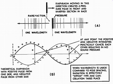
Fig. 9-2. Doublet operation of un-baffled diaphragm. ------- DIAPHRAGM
MOVING IN THIS DIRECTION CREATES A PRESSURE PULSE IN FRONT AND RAREFIED
SECTION IN BACK ---------- AT ANY POINT THE POSITIVE AND NEGATIVE INTENSITIES
PRACTICALLY CANCEL EACH OTHER RESULTING IN NO SOUND PRESSURE ---------
THEORETICAL DIAPHRAGM WITH POSITIVE PULSE FROM ONE SIDE, AND NEGATIVE
PULSE FROM OTHER SIDE ---------- WHEN WAVELENGTH IS LARGE COMPARED
TO POLE SPACING, RADIATION IS EFFECTIVELY "DIPOLE" TYPE AND
CAN CELLATION TAKES PLACE
A loudspeaker actually radiates sound from both sides of its diaphragm (Fig. 9-2A). However, these two sound fields are out of phase with one another. As the diaphragm moves forward, there is a pressure area directly at its front surface. At its rear surface, there is an area of rarefaction. In other words, two distinct wave radiations start traveling away from the respective sides of the loudspeaker diaphragm in an out of phase condition as if they had come from two adjacent bodies pulsing out of phase. Such a system is referred to as an "acoustic doublet" -- an obvious name -- and is illustrated in Fig. 9-2 (B) in which the two sides of the diaphragm are represented by a negative and a positive pole radiating respectively a "negative" and a "positive" wave. If these doublet sources are close together, it is obvious that the "negative" wave from one will be directly canceled by the "positive" wave from the other at almost all points in space. This is true, however, if the poles of the doublet are so close that their spacing is only a small fraction of the length of the radiated wave as shown in Fig. 9-2 (B). This means that the longer the wavelength (low frequency), the closer the poles comparatively speaking, and the greater the low frequency cancellation. This condition we readily recognize in any loudspeaker when tested on a work bench without benefit of any baffle at all. Under this condition, the doublet mode of operation is most effectively working, with the result that there is a complete absence of low frequency response.
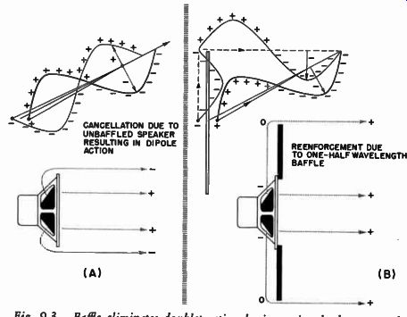
Fig. 9-3. Baffle eliminates doublet action by increasing back wave path
length by one-half wave length.
It is an obvious conclusion that to prevent the low frequency cancellation resulting from doublet operation, we should place some barrier between the front and the back, hence the baffle. Let us now examine the baffle size in terms of the wavelength being transmitted to see its effect upon doublet operation and its value in the elimination of such operation. Figure 9-3 shows a loudspeaker mounted on a small baffle. We will examine what happens at some point (P) in space without a baffle, and then with the baffle. Without a baffle, let us assume that the point (P) is at a given instant receiving a positive pulse from the front side of the loudspeaker. If the frequency of operation of the loudspeaker is low, there will be effective doublet operation. The wave from the rear of the loudspeaker will reach around and approach point (P) with a polarity directly opposite to that of the front wave.
The acoustic pressure at this point will be effectively canceled out, giving no response for this frequency.
Now let us put the small baffle in place, and assume the baffle size to be such that the wave from the rear has to travel an extra length of time equal to that taken up by one-half of the wavelength of the sound being transmitted. This means that now the out-of-phase wave from the rear of the speaker, having been delayed by the necessary amount, will reach point (P) in phase with the front wave, and the doublet action will have been eliminated. The result will be re-enforced lows rather than canceled lows.
Baffle Minimizes Doublet Operation
It is obvious that to eliminate this doublet action, the dimensions of the baffle should add an extra half wavelength of the desired low frequency sound to the total front to rear path. For frequencies above the dimensions at which doublet operation is minimized by the proper size baffle, there will be relatively smooth output. However, where the baffle size becomes too small to prevent doublet operation, the response curve begins to fall abruptly. It follows, conversely, that the larger the baffle the more effective will be the elimination of the doublet action for lower frequencies and the better will be the low frequency response.
Figure 9-4 illustrates the effect of increased baffle size on low frequency output. (Note: There will be improved smoothness of response above the frequency at which doublet operation occurs if the speaker is not mounted directly at the center of the flat baffle board or if an irregular baffle shape is used.) Although the open type baffle does assist in the improvement of low frequency response, it also has its shortcomings. In order to obtain acceptable low frequency extension from the open baffle type, the di mentions become rather unwieldy for normal home use. If we assume that for elimination of the doublet operation we need a baffle at least one-half the wavelength of the sound to be transmitted, for a frequency of 50 hz, which corresponds to a wavelength of approximately 22 feet, the distance from the speaker to the edge of the baffle would have to be 11 feet. Of course, the baffle may be folded back on itself as in the open back variety but such a baffle would still be an ungainly structure.
The open type baffle has another serious shortcoming in that there is no acoustic damping control of the free resonance of the loudspeaker.
It is true, however, that the air load the loudspeaker sees adds some mass" to the total moving system. This air mass lowers the resonance point slightly, and also reduces the excursion of the cone at resonance to some degree. In the main, however, there is no other type of acoustic constraint upon the motion of the diaphragm. It is virtually as free to move at its resonant condition as if the baffle weren't there at all. There will, therefore, be a tendency toward boominess in the response of the system at the resonant frequency. This boominess should not be interpreted as "bass." It is in truth a "one note" bottom that lends some feeling of bass, but is entirely out of proportion to the original signal.
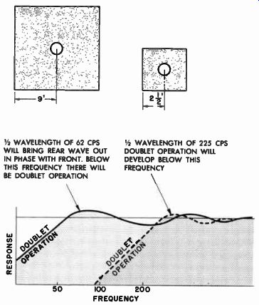
Fig. 9-4. Larger baffle lowers frequency at which doublet operation starts.
--------- 1 / 2 WAVELENGTH OF 62 HZ WILL BRING REAR WAVE OUT IN PHASE
WITH FRONT. BELOW THIS FREQUENCY THERE WILL BE DOUBLET OPERATION RESPONSE
1 / 2 WAVELENGTH OF 225 HZ DOUBLET OPERATION WILL DEVELOP BELOW THIS FREQUENCY 50 100 200 FREQUENCY
Because of the low frequency limitations of the open baffle and the raggedness of its response, this type of enclosure is practically never used in modern high fidelity practice. However, an understanding of its principles is necessary since most other enclosure structures are in essence attempts at eliminating the defects of the open baffle type.
A True Infinite Baffle Completely Eliminates Doublet Action
A natural extension of the open baffle is the true infinite baffle.
In this type of baffle there is absolutely no front-to-rear cancellation of sound energy at any frequency. This is accomplished by putting the speaker in a partition that completely seals off the front from the rear, but which at the same time allows perfect freedom of sound radiation from both sides of the loudspeaker into the areas they face. Such an infinite baffle might be the wall between two rooms as shown in Fig. 8-1 (D). If the loudspeaker were mounted in such a wall, one side of the speaker would have no effect upon the other. At the same time, the rooms on either side of the wall would enjoy virtually equal acoustic output.
The complete absence of doublet operation in this type of installation will ensure that the low frequency response obtained will be limited not by the baffle, but by the low frequency capabilities of the particular loudspeaker used in the installation. Thus, if an 8-inch loud speaker with a resonance of 125 hz were used in such a wall baffle, its response would be fairly smooth down almost to this frequency, then there would be a rise at 125 hz due to the resonance of the speaker. Progressing downward in frequency from this resonant peak at 125 hz, there would be a rapid drop in response at the rate of 12 db per octave. The same general condition would hold for a larger speaker, but with a change in resonant frequency as illustrated in Fig. 9-5.
This type of operation is characteristic of the wall type infinite baffle. It works down to the resonant frequency of the speaker being used, but fails rapidly below its resonant point. Its other shortcoming, as in the case of the open baffle, is the lack of control that may be exercised acoustically over the resonant frequency excursions of the loud speaker. With the exception of the air mass and radiation resistance loading, which will affect the resonance and damping of the speaker, for all practical purposes both sides of the loudspeaker are perfectly free unconstrained radiators into free space. The resonance is materially the same as in the un-baffled condition. There is a consequent one-note boominess to true infinite wall baffles (although not as pronounced as in open baffles) with rapidly dropping response below this area of resonance. This effect becomes more aggravated as the size of the speaker is increased, for the larger the speaker the lower the resonant frequency under normal circumstances; and consequently, the lower will be the undamped resonant frequency of the diaphragm excursion and the greater the output at the resonant point.
There are variations of the wall baffle that still constitute, in essence, true infinite baffles. One such variation is the closet installation, in which the speaker is mounted in the door of a closet, the rear of the speaker facing into the cavity of the closet. If the closet is large, its volume will for all practical acoustic purposes be equivalent to an open room, and the loudspeaker will perform as it would in a pure wall baffle, with the important exception, of course, that only one side of the loudspeaker will be doing useful work.
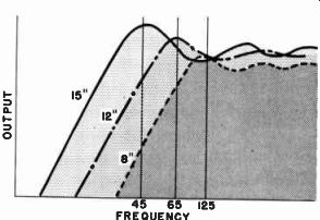
Fig. 9-5. The performance of the true infinite baffle (wall type) is
a function completely of the loud speaker itself with the sole purpose
of the baffle being the complete elimination of the dipole effect. After
this is accomplished the response capabilities of the speaker itself determine
the response of the system.
It is obvious that the installation of a speaker in a wall baffle in tended to feed two rooms must be made on the basis of a loudspeaker of the all-purpose wide range variety, in order to have equivalent performance from both sides of the loudspeaker. If a two or three-way speaker were used, only one room would benefit from the full operation of the speaker, while the other room (on the rear side of the speaker) would receive only the woofer portion of the response. Infinite baffles of the closet type exhibit good low frequency response down to the natural resonance of the speaker by virtue of the high order of radiation resistance of the speaker when mounted in such baffles; below this resonant point, the low frequency output drops at the rate of 12 db per octave.
Closed Box Raises Resonance of Speaker
There is another type of enclosure called an infinite baffle that is not strictly in that category. This is the completely closed box, with no openings other than the one in which the loudspeaker itself is mounted (Fig. 8-1C). The reason for calling this an infinite enclosure is quite obvious, considering that the back of the loudspeaker is completely sealed off from the front. In this sense only, the enclosure acts as does the true infinite wall baffle. However, there is one important difference between the wall baffle and the closed box, specially when the closed box takes on the small proportions necessary to make it suitable for placement in the usual living room. The relatively small and unrelieved volume of space that encloses the back of the loudspeaker becomes an acoustic restraint upon the loudspeaker. The small volume of air captured by the enclosure has no way of escaping and acts as an acoustic spring upon the loudspeaker. It stiffens the loud speaker and actually may raise the resonant frequency of the system (see Fig. 9-6) to some slightly higher value than the speaker had when it was un-baffled.
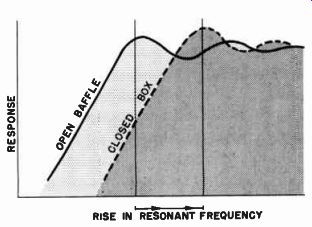
Fig. 9-6. Air captured in a sealed enclosure acts as an acoustic stiffener
upon the back of the loudspeaker and raises the resonant frequency of
the speaker.
We must be careful, however, in interpreting what actually happens to the acoustic performance of the system. It would be wrong to state categorically that the low frequency response would suffer be cause of this rise in resonance frequency. The matter must be considered in the light of the original resonance and the rise in the resonance frequency in relation to the size of the box in which the loudspeaker is to be operated. Let us illustrate this with a practical example, as indicated in Fig. 9-7. At (A) we have a loudspeaker with a natural resonance of 100 hz; mounted in an open baffle, it still has the same general resonant point and produces the response indicated. Now, if this same enclosure were to be sealed off at the back, making it a closed ...
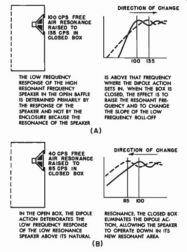
Fig. 9-7. Low frequency response is function of speaker resonance plus
enclosure size.
THE LOW FREQUENCY RESPONSE OF THE HIGH RESONANT FREQUENCY SPEAKER IN THE OPEN BAFFLE IS DETERMINED PRIMARILY BY THE RESPONSE OF THE SPEAKER AND NOT BY THE ENCLOSURE BECAUSE THE RESONANCE OF THE SPEAKER (A) 40 HZ FREE AIR RESONANCE RAISED TO 85 HZ IN CLOSED BOX IN THE OPEN BOX, THE DIPOLE ACTION DETERIORATES THE LOW FREQUENCY RESPONSE OF THE LOW RESONANCE SPEAKER ABOVE ITS NATURAL (B) IS ABOVE THAT FREQUENCY WHERE THE DIPOLE ACTION SETS IN. WHEN THE BOX IS CLOSED, THE EFFECT IS TO RAISE THE RESONANT FRE QUENCY AND TO CHANGE THE SLOPE OF THE LOW FREQUENCY ROLL-OFF DIRECTION OF CHANGE 85 100 RESONANCE. THE CLOSED BOX ELIMINATES THE DIPOLE ACtion , ALLOWING THE SPEAKER TO OPERATE DOWN IN ITS NEW RESONANT AREA
... box, the cone would be stiffened by the unrelieved air cushion at its back and the speaker resonance might go up to 135 hz. However, despite this increase in the resonant frequency, the actual low frequency output of the enclosed box system rolls off more slowly than the open back type, because of the elimination of the doublet action.
Suppose we substitute a speaker of much lower resonance, say 40 hz (Fig. 9-7B). In the same open back cabinet used before, the output of the 40 hz speaker will suffer from the same doublet action of the enclosure as did the higher frequency speaker, because it is the baffle and not the loudspeaker that determines where doublet action begins. Therefore, the low frequency output of this open system with the 40 hz speaker also begins to fall off at about 100 hz, despite the fact that it has a lower resonance. However, because it has a lower resonance, its output does not drop quite as rapidly as did that of the 100 hz speaker, as shown in the illustration. Now let this same en closure be sealed again at its back, providing a stiffening air cushion at the back of the loudspeaker. Again the resonance of the loudspeaker is raised because of this added stiffness. In the present instance, it may go up from 40 hz to perhaps 85 hz. Note that the rise in resonance of the low resonance speaker (from 40 to 85 hz) is much greater proportionally than the rise in resonance of the high resonance speaker (from 100 to 135 hz). This occurs because the same box volume presents a comparatively stiffer cushioning effect to a loose system (40 hz resonance) than to a system that is already comparatively tight (100 hz resonance), acoustically speaking.
The response of the same speaker (40 hz) in the closed box shows a low frequency peak at a point much lower in the band than in the open baffle, despite the fact that it has been stiffened by being enclosed. The doublet action has been entirely removed, and the low frequency response is now limited only by the resultant resonance of the speaker-enclosure combination. To summarize: The closed box raises the resonant frequency of the speaker. For a given size box the rise in resonant frequency will be much greater for a low resonant speaker than for a high resonant speaker. The overall performance is a function of both box size and speaker characteristic resonance.
Closed Box and Infinite Baffle Systems Have Single Resonant Peak
Despite the fact that the closed box makes possible better response than the open baffle and also provides some "infinite" baffle action with out recourse to breaking through walls, it does suffer from the same defects as true wall baffles and open baffles, but to a smaller degree.
All three types may develop a resonant condition that produces a single note boominess. This condition is most prevalent when a low resonance speaker is used in an enclosure of moderate size that does not stiffen the speaker sufficiently. Invariably, boxed enclosures are thoroughly treated internally with acoustic damping material, which materially reduces this resonant boominess. All in all, however, the infinite baffle does represent a means of obtaining acoustic performance decidedly better than that obtainable from the open baffle, particularly if a fairly large box is used. (Note: To prevent the stiffness of the enclosure from raising the loudspeaker's resonant frequency by more than 10 percent, the enclosure volume should be at least 3 1 / 2 cubic feet for a typical 8-inch speaker, 8 1 / 2 cubic feet for a typical 12-inch speaker, and 15 cubic feet for a typical 15-inch speaker.) Vented Enclosure Acts on Phase of Rear Wave Before It Emerges
One important disadvantage of the infinite baffle enclosure is the fact that radiation from the rear of the speaker is completely lost in the closed box. It cannot be made to do useful work because it has no way of getting out of the box. This condition is rectified in the "bass-reflex" (or "phase-inverter") enclosure. This is in all respects like the closed box, except that there is an opening, usually on the face of the enclosure. It would be simplifying the situation considerably to say that this opening allows the sound from the rear of the speaker to come around to the front. True, it does just that, but not before something important has happened to that sound. To provide an understanding of the action that takes place within the cabinet, we shall present briefly one or two simple concepts dealing with purely acoustic elements.
A volume of space of roughly symmetrical proportions represents an acoustical capacitance. If the reader refers to Fig. 9-8(A), he will see a structural configuration that represents a box with an inlet and an outlet. Let us now send sound into one opening. Nothing will come out of the other opening until the box portion has been "filled up," because this box is directly across the "line" - this structure has capacitance." It has the capacity to store the flow of sound. In Fig. 9-8(B) is a long hollow tube wound into the form of a coil. Now, when one attempts to send sound into this "coil," the pulsations of air (which has actual mass) will exhibit a true inertia effect. They have difficulty negotiating the turns of the tube because of the inertia of the pulses, and the tube acts as an acoustic inductor. It will have the property of preventing the flow of the sound pulsations. Even if this tube were straightened out, it would still exhibit acoustic inductance, or "inertance," which would impede the passage of sound through it just as a straight wire may exhibit a self-inductance that offers considerable opposition to the flow of very high frequency currents. Even if the tube were cut into small sections, each of these small sections would still produce the inertance effect. In fact, taking it to extremes, if a very thin section were cut and inserted in a partitioning wall to support it (in essence just a "hole in the wall"), it would exhibit its due measure of inertance.
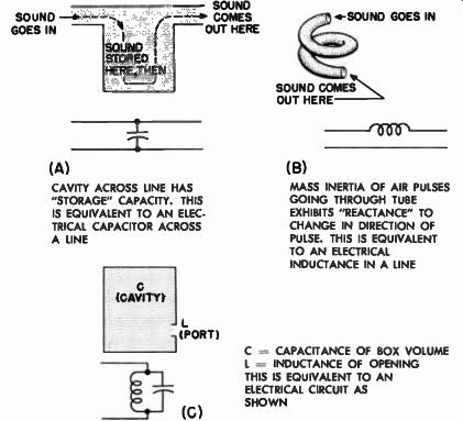
Fig. 9-8. Simple electrical analogies of acoustic elements in a vented
enclosure. -------------- (A) CAVITY ACROSS LINE HAS "STORAGE" CAPACITY.
THIS IS EQUIVALENT TO AN ELEC TRICAL CAPACITOR ACROSS A LINE (CAVITY)
l (PORT) (C) (B) MASS INERTIA OF AIR PULSES GOING THROUGH TUBE EXHIBITS "REACTANCE" TO
CHANGE IN DIRECTION OF PULSE. THIS IS EQUIVALENT TO AN ELECTRICAL INDUCTANCE
IN A LINE C CAPACITANCE OF BOX VOLUME L = INDUCTANCE OF OPENING THIS IS
EQUIVALENT TO AN ELECTRICAL CIRCUIT AS SHOWN
Bass-Reflex Enclosure has Tunable Acoustic Properties
Thus we come to the two basic acoustic properties that must be dealt with in the simple bass-reflex enclosure. We have the box itself, which has acoustic capacitance, and we have the hole (the port), which has acoustic inertance. This combination in a single structure of both capacitance and inductance (inertance), as shown in Fig. 9-8(C), rep resents a resonant circuit, the resonant frequency of which is a function of the actual values of the capacitance and the inertance. If either of these two elements or both are made variable, the combination of the two becomes a tunable circuit.
This is the important feature of the bass-reflex enclosure; it can be tuned to resonate with the loudspeaker with which it is to work.
The simplest type of bass-reflex enclosure is shown in Fig. 8-1(E), where the loudspeaker is usually mounted in the top section of the front panel and the opening or port placed near the bottom edge of the panel. By adjusting the port opening, the resonance of the en closure is altered so that it matches the natural resonance frequency of the loudspeaker itself.
Now, why all this emphasis on resonating the enclosure to the speaker? Simply because this gives us a direct means of matching the enclosure to the speaker, by means of which we may greatly improve the performance of the system over that of a closed box. The speaker and the enclosure become a system rather than just two components put together. Because the loudspeaker is located in intimate contact with the interior of the bass-reflex enclosure, we may say that the loudspeaker and the enclosure are closely coupled together. This means that the performance of the enclosure is dependent upon the speaker, and vice-versa.
Tuning Bass-Reflex Enclosure Converts Single Resonance to Dual Resonance
A very interesting phenomenon occurs when two circuits of the same resonant frequency are closely coupled together. The system no longer exhibits a resonance at the original resonant frequency of the individual sections. The original resonant frequency has disappeared completely, leaving in its place two other resonant frequency points, straddling the original as shown in Fig. 9-9. We have seen from Part 1 that at its resonant point of operation the speaker is working at its greatest efficiency. If we now carry over this principle of maximum efficiency at resonance points to the present situation, we see immediately that the area of high efficiency (in the low frequency region) has been increased by the extent of the spread between the two new resonant points. This extension of the resonance area to about an octave above and below the original resonance point produces an additional effect upon the performance of the system. The resonance peaks are considerably reduced in amplitude partly by the close coupling condition and partly by the radiation resistance. The system peaks thus become considerably damped. Resonant boominess all but disappears and is replaced by fairly smooth un-peaked response over a broad low frequency area.
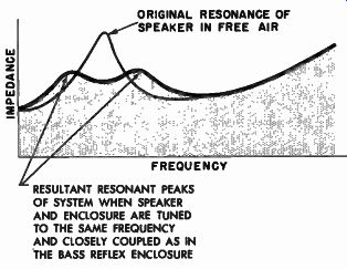
Fig. 9-9. Area of high acoustic efficiency is spread out over a broader
band by the two separated resonant peaks of the bass-reflex tuned system.
----------- ORIGINAL RESONANCE OF SPEAKER IN FREE AIR
RESULTANT RESONANT PEAKS OF SYSTEM WHEN SPEAKER AND ENCLOSURE ARE TUNED TO THE SAME FREQUENCY AND CLOSELY COUPLED AS IN THE BASS REFLEX ENCLOSURE
Phase of Rear Wave is Reversed Before it Emerges
There is one other important characteristic of bass-reflex operation that adds to its high level of performance. This is the degree to which the rear radiation is made to do useful work. Speaking very generally, if we can make use of this rear radiation, we have available about twice as much acoustic power. Now, this is not a matter of simply letting the sound come out of the box, for we know that if this sound emerges out of phase with the forward radiation, there will be cancellation rather than reinforcement. The trick is to bring this rear radiation out in phase with the front radiation.
A rigorous analysis of the mesh circuit phase relation that produces this reversal is beyond the scope of this treatment. It may be said, however, that the action of the acoustic elements of the enclosure is to reverse the phase of the sound coming out of the port for certain frequencies in the low frequency area. In a very general fashion we might explain this action on the basis of the flow of acoustic energy from the back of the speaker. It will be recalled that in the brief discussion of the acoustic elements of an enclosure a volume of space was referred to as an acoustic capacitance that has to be "filled" up before it can pass on any energy; that it stores acoustic energy like an electrical capacitor stores an electrical charge. So we might now come back to our bass-reflex enclosure and carry the analogy further by saying that the sound from the back of the speaker must fill the cavity of the en closure before it reaches the port. The sound from the back of the speaker is therefore delayed enough in time before it comes out of the port (without traversing any large baffle distance) so that when it finally does emerge, it does so in-phase with the front-radiated sound.
This, in a very general fashion, is the "phase-inverter" action of the bass-reflex cabinet, which makes the sound power from the back of the diaphragm as usable as that from the front of the diaphragm for low frequencies.
It must be realized that the phase inverting characteristic of the bass-reflex cabinet is effective only at the low frequencies. The "inertia" reactance of the port increases as the frequency of the air pulses is raised, just as the inductive reactance of a coil goes up for an increasing frequency of electrical current. The higher the frequency of the sound pulses trying to emerge from the port, the more inertia is exhibited by the air and the more difficult it is for these pulses to get through the port. Therefore, for the middle and upper frequencies, the bass-reflex enclosure reverts essentially to a closed box because all the radiation is from the front of the speaker. As the sound goes down in frequency, however, the port reactance also goes down. The sound can make its way out of the port, and the enclosure radiates both from the front of the speaker and from the port. This is the bass-reflex principle.
Port of Bass-Reflex Enclosure Has Radiation Resistance
The sound that eventually comes out of the port would not be radiated if the port were a pure inertance. For sound power to be radiated, there must be an acoustic radiation resistance for the sound pulsations to work with. We have seen from Fig. 9-1 that the radiation resistance of a vibrating diaphragm is a function of the size of the diaphragm and the frequency to be radiated. The pulsating air at the port opening is in reality a "mass-less" diaphragm. Its radiation resistance determines the efficiency of power transmission through the port. If the port is too small in relation to the wavelength, there will be low radiation resistance and low power output for the low frequencies.
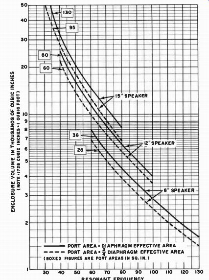
Fig. 9-10. Chart relating speaker resonance, speaker size, enclosure
volume, and port area for a bass-reflex enclosure.
Designing the Bass-Reflex Enclosure
For this reason, best performance of the bass-reflex system is obtained when the port area is between three-quarters and one times the actual effective area of the loudspeaker diaphragm. (This effective area is i where r is the radius of the piston equivalent to the speaker cone at low frequencies.) Thus, if an enclosure is to be made for an 8-inch speaker, one should provide a port opening of from 28 to 38 square inches; for a 12-inch speaker, the port opening should be from 60 to 80 square inches; and for a 15-inch speaker, the port opening should be from 95 to 130 square inches. 1 Once this port size has been chosen, the enclosure volume will be determined, for the two go hand in hand with the resonance of the speaker. Figure 9-10 is a chart for selecting the proper enclosure size for a speaker of a given resonance. This chart is made up for two conditions; in one the port size is equal to three-quarters the effective diaphragm area, and in the other the port size is equal to the effective diaphragm area. In the case of the larger port area (equal to the total active diaphragm area) the enclosure will necessarily be larger, but improved low frequency performance will result.
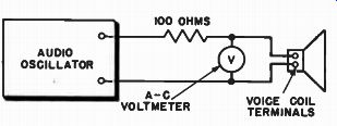
Fig. 9-11. Apparatus for determining the resonant frequency of a loudspeaker.
At the resonant frequency the voltmeter will read maximum.
In order to use this chart, it is of course necessary to know the resonant frequency of the loudspeaker. If this information is not avail able from the manufacturer of the loudspeaker or if one wants to determine the exact resonant frequency for himself, the procedure is not too complicated. It is necessary, however, to have at one's disposal some elementary test equipment, such as a properly calibrated audio oscillator and a simple a-c voltmeter, in addition to a resistor of about 100 ohms. (This value is not at all critical.) Figure 9-11 shows how these elements are connected in order to find the resonance frequency of the unmounted speaker. As the audio oscillator is slowly swept through the low frequency end of the audio spectrum, it passes through the resonance frequency of the loudspeaker. The voltmeter, which is connected directly across the voice coil terminals, will show a definite rise in voltage at this frequency. The point at which the maximum reading of the voltmeter is obtained in the low frequency area is the resonant frequency of the loudspeaker. (Note: In the above procedure do not place the speaker face down on a table or bench as its resonance will be completely damped out. The cone should point into free space as much as possible.) Once this resonant frequency has been determined, and it has been decided whether the larger port area (for optimum port performance) or the smaller port size (to reduce the volume of the enclosure in general), will be chosen, the actual volume of the enclosure may be selected from the chart. In any event, it is desirable to make the port somewhat larger than necessary so that it may subsequently be tuned to the exact resonance where precision is desired.
-- Refer to Fig. 12-6 for discussion of effective piston area.
Note that the chart gives the interior volume of the enclosure.
For exact results, this volume should be increased by the space occupied by the loudspeaker itself, the internal bracing, and the sound absorption material used. Typical approximate volumes displaced by loud speakers are 250 cubic inches for an 8-inch speaker, 650 cubic inches for a 12-inch speaker, and 1400 cubic inches for a 15-inch speaker.
The volume occupied by the internal sound absorption material should be calculated from the area covered and the thickness of the material when held temporarily tightly compressed.
Tuning the Bass-Reflex Enclosure
This tuning of the finished system may be accomplished by closing off a portion of the opening with a movable panel of wood until the system is exactly tuned. Critical tuning may be accomplished by using the same equipment as before, but progressing in a somewhat more detailed fashion, as follows. Start with the port in its most open condition. Sweep the oscillator over the low frequency area of the spectrum very slowly, noting the frequencies at which the voltmeter connected across the voice coil shows a voltage rise. Two peaks of resonance will usually be found, one higher in frequency than the original re sonant frequency of the unmounted speaker, and the other lower.
However, the amplitude of these peaks will not necessarily be equal, nor will the peaks straddle the original resonance equally on either side, unless the enclosure should happen to be properly adjusted. Correct tuning exists when the two resonance peaks are of equal amplitude as shown by the voltmeter readings and when these peaks are equally displaced from the free air resonance. It will also be observed that when these two peaks are balanced in amplitude, their common amplitude is considerably smaller than the original free air resonance peak voltage. This is an indication of the damping effect on the speaker of the closely coupled, properly tuned bass-reflex enclosure. The volt meter reading is actually a measure of the excursion of the diaphragm of the loudspeaker.
Figure 9-12 shows a set of experimentally determined tuning curves for a bass-reflex enclosure for various conditions of port opening. Note how the amplitudes of the two peaks tend to equalize and how their frequencies shift upward as the port is opened and the correct adjustment is approached.
Although proper tuning of the system may be made by the methods described above and considerable damping accomplished, use of this procedure does not necessarily mean that optimum damping has been accomplished. Optimum damping in the combined speaker enclosure system occurs when the Q of the system is equal to unity. This means that the ratio of resistance in the circuit to inductive reactance is unity.
It will be realized that since we have not as yet made any resistive compensations in the above system, we have obviously neglected to examine the damping factor critically. Fortunately, it is not at all difficult to make the necessary adjustments to the Q of the system to ensure that no transient "ringing" or "hangover" remain in the system.
We have seen in Part 1 that ringing in the speaker system is the condition in which the speaker overshoots and continues to oscillate for a short period of time after a single pulse has been applied to it. Hang over is the tendency of the speaker to continue to vibrate around its equilibrium no-signal position after the pulse has been removed. In order to make the necessary adjustment to eliminate these undesirable effects from the enclosure system, all the constructor needs is a fresh flashlight battery and some silk cloth of the thickness and weave of ordinary handkerchief material.
When tightly stretched across an opening through which sound is to flow, like the port, a layer of such cloth exhibits an acoustic resistance. The many small holes in the cloth and the fibrous filaments of the material over the opening provide a resistive block to the sound waves. This works only when the cloth is tightly stretched. When it is not, it may try to vibrate under the influence of the sound. If this happens, the cloth acts like a membrane and adds inductance to the circuit as well as resistance.
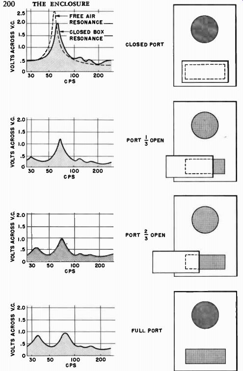
Fig. 9-12. Experimentally determined impedance curves of a bass-reflex
enclosure as its port area is changed from zero to full port. (Milton
S. Snitzer, "Adventures With a Bass Reflex," Audio Engineering,
January 1954.)
The number of layers of resistive cloth to be stretched over the port is determined by the following test. Connect one side of the dry cell to one of the voice coil terminals, then make provisions so that the other terminal of the loudspeaker may be readily connected and disconnected from the battery. Since the dry cell has a constant d-c voltage, the application of this fixed voltage to the loudspeaker will constitute a "unit pulse," for once it is applied to the speaker, it persists unchanged until it is removed. As the battery connection of the loudspeaker is completed, the loudspeaker will make a sound that can best be described as a "bong" (if the system is not properly damped). When the battery is disconnected, the loudspeaker will make a similar sound. The "bong" represents a ringing condition of the loudspeaker, brought about by the application of a non-ringing unit pulse. The objective of this test is to reduce the sound of the "bong" to that of a "click," for the click is truly representative of a steady pulse signal. If the "bong" continues, additional layers of cloth should be applied to the port opening, one at a time, until the "bong" has been reduced to a "click." When this condition has barely been reached, the system is critically damped.
Application of more material than necessary does not constitute adding more of a "good thing." Too much damping material will over-damp the system, causing it to operate inefficiently.
In converting the "bong" to a "click," it is important to make sure that the conversion is complete on the breaking of the battery circuit as well as the making, for often the "make" portion of the test will arrive at the click condition before the "break." One should not stop, therefore, when the click is heard on the completion of the circuit; he should continue with the damping procedure until the click is also barely heard on the breaking of the circuit. When this damping operation is successfully completed, not only will the system be tuned properly for optimum smooth low frequency response, but it will also be free of undesired transient generation. This damping material in the port circuit should not be confused with damping material used to line the interior of the enclosure. The port damping material is used primarily to provide the proper resistive component in the radiating "circuit" so that the correct ratio of resistance to reactance in this circuit may be obtained. The damping material on the inside of the enclosure is used to prevent standing waves within the enclosure (which would cause the enclosure to deviate from true bass-reflex action in the...
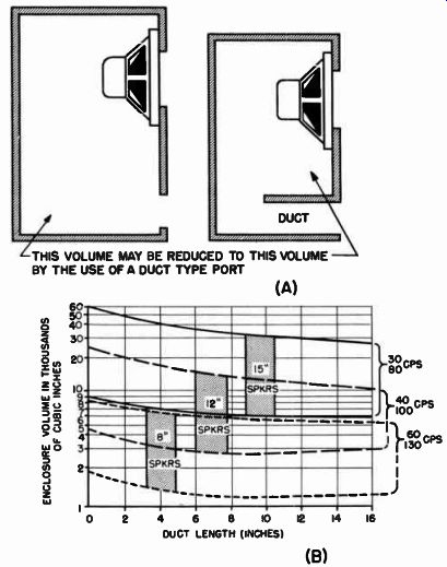
Fig. 9-13. Reduction in size of enclosure that may be realized through
use of a duct, which creates a larger port inertance, permitting smaller
cavity capacitance.
...low frequency end ) and to minimize mid-frequency irregularities. These matters will be discussed in Section 14.
Enclosure Volume May be Reduced by Venting With a Duct
In developing the concept of acoustic inertance for purposes of explaining the action of the bass-reflex enclosure, mention was made of the inertance effect of a long tube. In the development of the bass reflex enclosure, we reduced this tubular inertance in size so that it became a mere hole in a partition. This explanation was given purely for illustrative purposes, since most of today's bass-reflex enclosures are constructed with only an opening as a port (for ease in construction, especially by the home hobbyist). It is possible, however, to use a tube or a duct advantageously as the inertance element of the bass-reflex enclosure with beneficial results. The duct, as shown in Fig. 9-13 (A), will exhibit considerably more inertance than the port of the same cross sectional dimensions. Because of this increased inertance, the volume of the cabinet may be reduced to get the same resonance frequency condition. The chart in Fig. 9-13 (B) graphically indicates the reduction in size of the cabinet that may be realized for ducts of various sizes. Thus, where construction costs or problems are not considered of importance and reduced size of enclosure is, the duct vent enclosure shown will prove beneficial. The length of the duct need not be more than necessary to reduce the cabinet volume to its minimum as shown by the graph. In fact, a length about one-half or three-quarters of that indicated by the graph will be perfectly acceptable, because the longer duct takes up more space in the enclosure, and that space must be made up in other dimensions. It is wise, therefore, to use a duct that is moderately short, but of sufficient length to bring the cabinet volume down to the desired size.
Bass-Reflex Enclosure is Flexible and Adaptable to Many Speaker Types
The bass-reflex enclosure enjoys a wide popularity because of the relative ease with which it may be constructed, its adaptability to a wide variety of speaker types, and the ease with which adjustments may be made to make it a matched system with the speaker. Because of the fact that in this enclosure the speaker faces directly out from the enclosure into the listening area, any type of speaker may be used.
A speaker (such as a coaxial or triaxial unit) that must face directly toward the listener must be used with a direct radiator type of enclosure (such as the bass-reflex) in which there is free forward radiation.
Yet the bass-reflex enclosure is not limited to such speakers. If a multi-speaker system is desired with separate woofer, midrange, and tweeter units, the woofer may be mounted in the bass-reflex system and the other components in a small auxiliary cabinet on top or on the front face of the enclosure, without in any way upsetting the performance of the bass-reflex system.
Because of the adaptability of this type of enclosure to single wide range speakers or two or three-way multi-speaker systems, it lends itself admirably to the program of progressive speaker expansion described in Part 1. One may use the cabinet to house his single wide range speaker for general purpose reproduction, and then (by the addition of the proper crossover network and midrange and tweeter units) convert the system in the same cabinet to a multi-speaker system, still utilizing the original wide range speaker, converted by the network to function as a woofer.