AMAZON multi-meters discounts AMAZON oscilloscope discounts
1. Introduction
The term feedback as used in electronics describes a process for transferring energy from the output circuit of a device (such as an amplifier) to its input circuit. When this transfer is accomplished in such a manner that the energy produced at the output circuit when feedback is used exceeds the energy so produced when feedback is not used, this process is defined as "positive" or "regenerative" feedback. When this transfer takes place in a different manner so that the output energy in the presence of feedback is less than that produced in the absence of feedback, this process is defined as "negative," "degenerative," or "inverse" feedback.
Both types of feedback are of the utmost importance in modern electronic design. However, each type is a subject in itself, and this guide is concerned only with inverse feedback.
2. Advantages of Negative Feedback
All electronic amplifiers develop a certain amount of hum or noise, or both. Further, the gain of any amplifier varies at least a small amount with the frequency of the signal it amplifies. In other words, no amplifier has a perfectly "flat" frequency response or complete freedom from noise. In addition, the amplifier behavior is likely to change as tubes are replaced, as circuit components change value, or as power supply voltages vary. As will be explained m detail in later portions of this text, these and other amplifier defects may be wholly or partly eliminated when inverse feedback is used.
The uses of feedback are numerous. As a rule, however, the principal effect underlying each use of inverse feedback is the control of gain. All other feedback effects are directly related to the effect on gain.
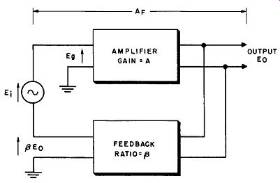
Fig. 1. Basic feedback arrangement.
3. Effect of Negative Feedback on Gain The gain control principle involved in the use of inverse feed back can best be understood from a study of the system shown in Fig. 1. An amplifier having a voltage gain denoted by the symbol
A produces an output voltage, E0. An incoming alternating signal, E1, is supplied to the input of the amplifier.
A fraction, Beta (which is always less than 1) , of the output voltage is fedback through a feedback network to the input of the amplifier as a feedback voltage, E0.
When the feedback voltage is negative, ~ is negative. This ties in with the fact that when inverse (negative) feedback is used, the amplifier output energy in the presence of feedback is less than the output energy where no feedback is used. Consequently, to be negative, the feedback voltage must always act in opposition to the incoming signal.
At the point to which signal is fed back, the feedback voltage and the input signal voltage (from the previous stage) add together to produce the total effective input to the amplifier.
If feedback is negative, the feedback voltage opposes the signal voltage, so the net total amplifier input voltage is equal to the numerical difference between the signal input and feedback voltages.
This is illustrated in Fig. 1. The amplifier is assumed to have amplification A in the absence of feedback. The feedback network takes part of the amplifier output voltage (E_0 ,) and transfers it to the input circuit. The fraction of E0 that is fed back is symbolized as p, sometimes called the "feedback ratio." For example, suppose the signal output of the amplifier is 100 volts, of which 50 volts is fed back to the input.
Then: 50 p = - = 0.5 100
From this it can be seen that the voltage (E1b) fed back to the input is:
Normally, we take the signal voltage at the point to which feedback is applied as a reference. Then E0 may be either positive or negative. For example, if there is one stage of amplification, a 180-degree phase shift is introduced, and E0 has a negative value.
If there are two stages, E0 is positive. (In both cases it is assumed that input voltage is at the grid and output voltage is at the plate.) If E 0 is negative, some of it can be tapped off and applied directly to the input for negative feedback. In such a case p is said to be positive because it has not changed feedback phase. If E_o is positive, it must be inverted before application to the input. This inversion is accomplished in the feedback network when p is negative.
From the above it can be seen that for negative feedback, either E0 or p, but not both, must be negative. This will presently be checked mathematically.
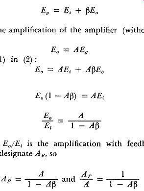
We have now defined basic factors well enough to set down the fundamental relations applying to Fig. 1. We call the signal voltage obtained from the previous stage E; and the total signal into the amplifier with feedback Eu.
Feedback signal Beta E_0 is applied to the input so as to add to signal voltage E; to produce input signal Eu. Expressing this mathematically:
E_Q = Ei + ~E0 (1)
Because the amplification of the amplifier (without feedback) is A,
Substituting
(1)
(2)
(3)
But the ratio E0 /E1 is the amplification with feedback applied, which we will designate A,.., so

(4)
Equation 4 is a basic universal relation, upon which most feed back theory is based. Most negative feedback networks do not have gain, so ~ is less than 1. Remembering this, it can be seen in Equation 4 that if A and ~ are both positive (no phase shift or phase shift a multiple of 360 degrees) or both negative (180-degree shift)
the gain with feedback is greater than gain without feedback and feedback is positive. For negative feedback, either A or ~ must be negative, and the gain with feedback must be less than the gain without feedback.
An example of how negative feedback may be obtained in an actual circuit is shown in Fig. 2. This is a simple resistance coupled amplifier, whose output signal voltage is E0 and whose input signal voltage is E;. E0 is 180 degrees out of phase with E;, as in any resistance-coupled amplifier. C1 blocks plate d-c voltage E~ from the grid, but has enough capacitance to appear as a short circuit for signal voltages. E0 is coupled through C1 to the voltage divider formed by R1 and R2. The portion of this voltage appearing at the grid is the ratio of R2 to R1 + R2, so R2 Efb = Eo R1 + R2
Since E0 is in phase opposition to E;, so is E1b, and the feedback is negative.
Let us now see how we may apply Equation 4 to determine how much the gain of the stage of Fig. 2 is reduced by the addition
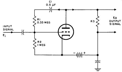
Fig. 2. Example of negative feedback arrangement.
of feedback network R1 C1. First, assume that the gain without feedback (A) is 10. ~ is the portion of E0 fed back, so
R2 R1+ R2 1 + 0.33 I 1.33
0.75
Because ~E0 is direct feedback with no phase change from E0 , ~ is positive. Because E0 is opposite in phase to E;, A is negative. We may now substitute m
Equation (4) : 1 - A~ 1 - (-10 X 0.75) I + 7.5 I 8.5
0.118
In other words, the gain after feedback circuit R1 C1 has been added is 10 x 0.118 = 1.18. In this example there is a relatively large amount of feedback, hence the extreme reduction in gain.
The preceding example shows how inverse feedback has the effect of dividing the normal gain by the quantity (1 – Beta A). This quantity is defined as the feedback factor. Large amounts of feed back arc normally used, and Beta A becomes large compared to l, so the quantity (1 - Beta A) is approximately equal to the quantity (- Beta A). For example, if (1 - Beta A) = 100, (-Beta A) = 99. The quantity (-Beta A) is itself often referred to as the feedback factor, and the reader should take care not to become confused by identical use of (1 - Beta A) and (- Beta A). When large amounts of feedback are used, the amplifier gain in the presence of feedback (A 1.,) is approximately equal to the quantity:
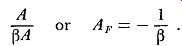
(5)
Thus the gain of an amplifier using large amounts of inverse feedback depends only upon ~, and is unaffected by changes in the amplifier gain (A) when feedback is not used. This characteristic of feedback prevents the amplifier behavior from being sensitive to small changes in tube characteristics caused, for example, by aging of tubes, or to small variations in power supply voltages. Effectively, the amplifier behavior is held uniform over long periods of time.
For this reason, inverse feedback amplifiers are widely used in vacuum tube voltmeter circuits, because accurate instrument calibration can thus be maintained despite tube changes or replacements. It will be noted that feedback can be used with either de or ac amplifiers. In the de amplifier, inverse feedback is obtained through the use of incoming signals and feedback voltages that are opposed in polarity; in the ac amplifier, the signals and feedback voltages are opposed in phase.
In electronic terminology, changes in power are often expressed in terms of decibels (db) . Thus, if the output power of an amplifier changes from P1 watts to P2 watts, the change in power as expressed in decibels is equal to the quantity
10 log10 (P2/P1)
(6)
The ratio of two voltages can also be expressed m db, by the expression (7)
… where voltage changes from E1 to E2
In a similar manner, changes in amounts of feedback are often expressed in decibels. The amount of feedback is actually indicated by the reduction in amplifier gain. Thus an amplifier with 20-db feedback is one in which the gain has been reduced 20 db by feedback.
As an example of expression of feedback in db, consider the previous example. The gain of the stage was reduced from 10 to 1. 18. First express each gain in terms of db:
Without feedback db = 20 log10 (10) = 20 X I = 20 db
With feedback db= 20 log10 (1.18) = 20 X .07 = 1.4 db
The reduction of gain in db is 20 - 1.4 = 18.6 db.
Therefore, the circuit of Fig. 2 can be said to have 18.6 db of feedback.
4. Effect of Negative Feedback on Amplitude Distortion
No practical amplifier can amplify an incoming signal in such a manner that its amplified output signal is a perfect reproduction of the incoming signal. In particular, all amplifiers exhibit some degree of amplitude distortion; that is, the amplified output signal contains some frequency components not present in the incoming signal. Let the distortion voltage present in the output signal when feedback is not used be equal to D, and let D1 be the value of the distortion voltage present when inverse feedback is used. Then if the output signal in the presence of feedback is adjusted to the same level as when feedback is not used, a distortion voltage (~D1) is fed back to the input of the amplifier. This distortion voltage is amplified to yield an output distortion voltage of ~AD1 where A is the gain of the amplifier without feedback. This output distortion voltage adds to the distortion (D) that would be present without feedback, so

(8)
Thus the distortion when feedback is used is equal to the distortion when feedback is not used divided by the feedback factor.
5. Effect of negative feedback on Frequency Response
The gain of an amplifier varies at least a little with frequency.
Assume that an amplifier that does not make use of feedback has a gain A 1 for one signal frequency and a second and different gain A2 for another signal frequency. When inverse feedback is used, the gain for the first signal frequency A_1F will equal the quantity A_1/ (1 - Beta A,). Similarly, the gain for the second frequency A_2F, will equal A/ (1 - Beta 2). Then the ratio of these two gains in the presence of feedback will be

(9)
Thus the ratio of these two gains in the presence of feedback is equal to the ratio when feedback is not used multiplied by the factor ( 1 – Beta A1) / ( 1 - Beta A2). The net result is that the gains at these two signal frequencies are more nearly the same when feedback is used.
As an example, consider an amplifier in which amplification at two different frequencies, without feedback, is
Amplification A1 at F 1 = - 10
Amplification A2 at F2 = - 1
The ratio of gains at the two frequencies 1s 10: 1.
Now suppose feedback, with Beta = 0.5 is applied.
Then
=4
Thus frequency components that without feedback had a gain ratio of 10 have a gain ratio of only 4 after feedback has been applied.
The frequency response of the amplifier is thus improved.
6. Effect of Negative Feedback on Hum and Noise
Amplifier hum is caused by the amplification of undesirable alternating voltages (for example, alternating filament voltages sup plied to the tubes in the amplifier). Amplifier noise is caused by tube microphonics, noisy resistors, and similar effects. When the in coming signal supplied to the amplifier contains hum or noise generated in earlier amplifier stages and extended to the amplifier itself, the output signal from the amplifier will contain the same percentage of hum or noise, whether or not inverse feedback is used.
This result follows from the fact that, although the amplifier gain is reduced through action of inverse feedback, both the useful portion of the incoming signal and the hum or noise component of this signal are amplified to the same extent.
However, if the hum or noise generated within the amplifier is subjected to inverse feedback action, this internal hum or noise will be reduced in the same manner and to the same extent as the amplifier gain is reduced by feedback. Proof that this reduction in noise or hum is actually accomplished is somewhat complex mathematically and will not be discussed here. [1]
When noise is present in a low gain amplifier, (for example, in an audio preamplifier) there is little advantage in using feedback to reduce noise; the use of feedback diminishes the amplifier gain to such an extent that additional amplification is required. This additional amplification raises the noise level to substantially its original value.
7. Types of Inverse Feedback
Inverse feedback can involve current feedback, voltage feedback, or combined current and voltage feedback. Each type of inverse feedback has a characteristic effect on amplifier operation, particularly on amplifier output and input impedances, as will be shown in subsequent Sections. However, each type of feedback will first be defined.
8. Current Feedback
The circuit shown in Fig 3 illustrates current feedback. Here the feedback voltage is derived from the voltage appearing across resistor R0. This voltage is equal to the quantity I_o R_0 where
I_0 0 is the amplifier output current flowing through resistor R0. Therefore, the feedback voltage is proportional to the output current and is defined as current feedback.
When current feedback is used, if the load impedance connected to the amplifier increases, the output current will decrease. As a result, the feedback voltage will also decrease, causing the amplifier gain to increase and the output current to increase. Thus, if the in put signal is held constant, the output current tends to remain constant despite changes in output impedance, and the circuit of Fig. 3 acts as a constant current generator.
1. For a detailed discussion of this reduction, sec F. Langford-Smith (ed.), Radiotron Designer's Handbook (4th ed.; Sidney, Australia: Wireless Press, 1952).
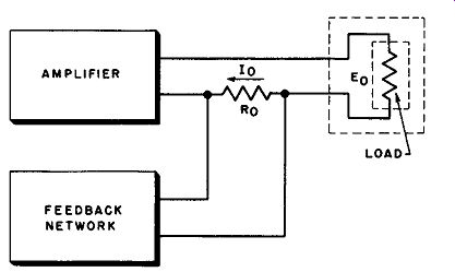
Fig. 3. Current feed back arrangement.
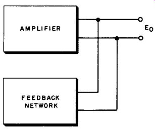
Fig. 4. Voltage feed back arrangement.
9. Voltage Feedback
In the circuit shown in Fig 4, the feedback voltage is derived directly from the output voltage, E0. Since the feedback voltage is proportional to the output voltage, this type of feedback is called voltage feed back.
When the load impedance is increased in this arrangement, the output voltage increases, the feedback voltage increases and the amplifier gain is reduced. This reduction in gain acts to reduce the out-put voltage. Thus, if the input signal is held constant, the output voltage tends to remain constant despite changes in output impedances, and the circuit of Fig. 3 acts as a constant voltage source.
10. Combined Current and Voltage Feedback
Both current and voltage feedback can be combined in one circuit, as shown in Fig. 5. The output voltage ( E0) appears across potentiometer P0 , so that the potential appearing at the arm of potentiometer P0 is proportional to the output voltage. In addition, the output current flows through potentiometer P;, and the potential appearing at the arm of potentiometer Pi is proportional to the output current.
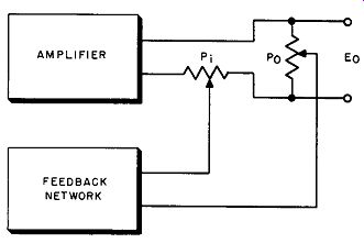
Fig. 5. Combined current and voltage feedback.
The feedback voltage is proportional to the difference between these two potentials, and therefore represents a combination of current and voltage feedback. This combination of feedback 1s some times called "bridge" or "hybrid" feedback.
11. QUIZ
(1) What is feedback?
(2) Explain the difference between regenerative and inverse feedback.
(3) Why is feedback used?
(4) How does negative feedback affect amplifier gain?
(5) Explain the difference between current and voltage feedback.
(6) What is meant by the term 20-db feedback?
(7) When large amounts of feedback are used, what is the relationship between amplifier gain and the feedback fraction Beta ?
(8) What is the effect of negative feedback on hum or noise?
(9) What is bridge feedback?
(10) What is the effect of negative feedback on amplitude distortion?