AMAZON multi-meters discounts AMAZON oscilloscope discounts
When the output energy from one electronic device is to be supplied as input energy to a second device, the output impedance of the first device must be matched to the input impedance of the second device; if it is not, there will be an excessive loss of power.
For example, audio power amplifier tubes have high plate impedance, yet they must supply power to one of more loudspeakers, which are low impedance devices. If these two devices were to be connected directly together, the impedance mismatch would be so great that the speaker would not receive enough power to produce the desired sound level. Impedance mismatch can also have other undesirable effects, such as increasing distortion. Therefore, an output transformer is used as an impedance matching device.
When inverse feedback is used, both the input and output impedances of the device are affected. Therefore, in order to prevent impedance mismatch, it is necessary to understand the nature and degree of changes in impedance caused by the use of inverse feedback.
12. General Considerations
Before proceeding to a consideration of more specific situations, let us examine some of the general factors involved in the influence of feedback on input and output impedance.
Without feedback, the impedances of the amplifier are deter mined by the impedance values of components in the circuit. The change of impedance caused by feedback results from modifications feedback makes in the way currents vary with voltages. Thus, if a signal voltage swing is upward, but there is negative feedback, the resulting current may swing upward more slowly than without feed back. In such a case the impedance has been raised, because the current response has been lowered as though more component impedance had been added.
Input impedance change due to feedback is influenced only by the currents and voltages in the input circuit in virtually all practical circuits. Similarly, output impedance is affected by the currents and voltages in the output circuit. Thus input impedance is substantially independent of the way in which feedback voltage is obtained from the output circuit, and output impedance is independent of the way in which the feedback voltage is applied to the input.
We shall consider the application of feedback both in series and in parallel with input voltage. Since the output circuit does not affect the impedance of the input circuit, the effect of feedback on input impedance is the same for either voltage feedback or current feedback.
For output circuits we shall also consider voltage feedback and current feedback. The effect of feedback on output impedance is the same whether the feedback is applied in parallel or in series with the input voltage.
Another factor of importance is the relative impedance of the feedback circuit itself; this impedance should usually be negligible.
To insure this, certain relationships must be maintained. First, if feedback is applied in series with the input voltage, its effective impedance must be negligibly low in order not to disturb the circuit.
Second, if the feedback is applied in parallel with the input circuit, the feedback circuit impedance must be relatively high, so that the feedback circuit acts as a constant-current device, and the input signal voltage is not affected by feedback. With the series connection, the input and feedback voltages add to produce the amplifier input voltage; with the parallel connection, the input currents add.
13. Feedback Voltage in Series with Input Signal
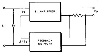
Fig. 6. Feedback voltage in series with input signal.
Figure 6 shows a current feedback arrangement in which the feedback voltage is in series with the input signal. The amplifier, when no feedback is used, will have an input impedance Z1 because of coupling capacitors, grid resistors, stray grid-to-ground capacitance, and so forth. Then, if the input signal is E;, the current through this impedance (I;,;;) will be E/Z;. It will be assumed, as is normally the case, that the impedance of a series connected feedback network (as in Fig. 6) is much smaller than the amplifier input impedance. Thus the network impedance need not be considered in this discussion.
In this situation, it is desirable to assume that E0 is kept at the same value for feedback and non-feedback conditions. In other words, without feedback the input voltage is Eg. Then, with feed back, the input voltage must be raised to a higher value of E; to restore the same E0 • Z; is the input impedance of the amplifier in the absence of feedback; ZF is the input impedance with feedback.
(10)
(11)
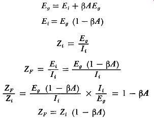
This says that the input impedance is increased by the feedback factor when feedback is added to a series-connected circuit.
EXAMPLE: An amplifier has an input impedance of 20,000 ohms without feedback, and its gain is -10. What is the input impedance if feedback with Beta = 0.1 is added?
ZF = Zi (1- Beta A) = 20,000 [1- 0.1 (-10)] = 20,000 X 2 = 40,000 ohms
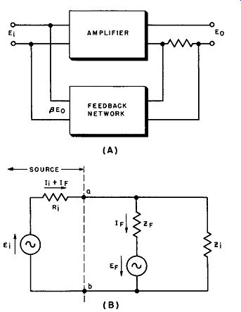
Fig. 7. Feedback voltage in parallel with input signal.
14. Feedback Voltage in Parallel with Input Signal
Sometimes the feedback is connected in parallel with the input signal, as indicated in Fig. 7 (A). As previously explained, with such a connection the feedback circuit impedance must be relatively high, and the feedback source becomes a constant-current generator.
To visualize this properly, consider the input circuit itself, illustrated at (B) of Fig. 7.
The incoming signal "sees" the impedance between points a and b "looking" from the left. The feedback voltage (EF) is connected through its impedance (ZF) to the input terminals. If EF is connected for negative feedback, so as to oppose E1 across Z1, it aids the current around the loop EF-E1-R1-ZF.
Thus the current feeding into the circuit at a-b is greater than the same current with out feedback, and the input impedance is effectively lowered.
Let us neglect Z1, since it has the effect merely of further lowering the impedance, and consider the remainder of the input circuit.
(A); (B)
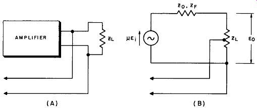
Fig. 8. Output circuit with voltage feedback.
The voltage remains E; whether or not there is feedback; only the current changes. Since impedance is inversely proportional to current at a given voltage:
(12)
With negative feedback the currents are additive, hence input impedance with feedback is lower than input impedance without feedback for the shunt connection.
Because the feedback and signal currents depend upon source and feedback impedances, and these are rather complex, a complete solution in terms of Beta and A is beyond the scope of this guide.
However, Equation 12 shows the important fact that feedback lowers input impedance in this arrangement.
15. Output Impedance with Voltage Feedback
To demonstrate the effect of voltage feedback on output impedance, as in the arrangement of Fig. 8 (A) we must consider an equivalent circuit as shown at (B) in Fig. 8. The output impedance is the output voltage source impedance, and is equivalent in the no-feedback case to plate resistance rP. In the following derivations, these symbols are employed:
µ = amplification factor of output stage without feedback
µF = amplification factor of output stage with feedback
A = amplification without feedback
AF = amplification with feedback
E1 = input signal voltage without feedback
EF = input signal voltage with feedback
Z0 = output impedance without feedback (rp) (normally resistive)
ZF = output impedance with feedback (normally resistive)
ZL = load impedance (normally resistive)
E0 = output signal voltage without feedback
E0 F = output signal voltage with feedback Without feedback, by voltage divider action:
(13)
(14)
(15)
This expression for E0 with feedback is the same as the equation for E0 without feedback, except that:
- µ
µF - 1 - µ~ and (17)
Thus, with voltage feedback, output impedance is reduced in pro portion to the feedback factor increase, using amplification factor µ instead of A. If the feedback extends around more than the output stage, µ is replaced by µA, whe1'e A is the amplification between the feedback application and the final stage. This modification is necessary because the output stage is a power (rather than voltage) stage.
(A) (B)
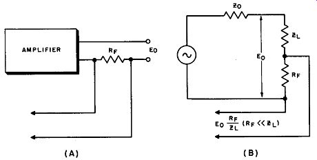
Fig. 9. Output circuit with current feedback.
EXAMPLE: Negative feedback with ~ = 0.2 is provided around a power stage whose amplification factor is -20 and whose plate impedance is 6000 ohms in the absence of feedback. What is the effective output impedance with feedback? What is the new effective amplification factor?
---------------
16. Output Voltage with Current Feedback
In current feedback, the output circuit conditions are changed by the addition of series resistor R -, illustrated in Fig. 9 (B). RF must be small compared to Z1,. Otherwise, the same symbols will be used here as in the previous discussion of voltage feedback impedance. With no feedback in this circuit:
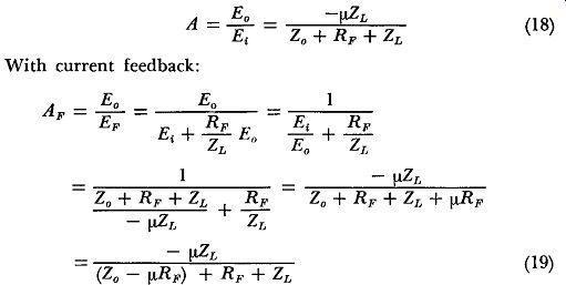
(18), (19)
This expression is the same as the expression for gain without feedback (Equation 18), except that the output impedance has changed from Z0 to Z0 - µR1,,.
Since no allowance is made in this arrangement for inversion in the feedback network, µ must be negative for negative feedback. Thus output impedance is effectively increased by negative current feedback.
EXAMPLE: An output stage with an amplification factor of -10 has a plate resistance of 10,000 ohms. What is the effective plate resistance after negative current feedback is added, using a 100-ohm feedback resistor?
ZF = Z0 - µRF = 10,000 - (-10 X 100) = 11,000 ohms
17. Combined Current and Voltage Feedback (Bridge Feedback)
In certain electronic applications (for example, when an amplifier is to supply energy to a transmission line), the output impedance must have a value lower than that obtainable through current feedback but higher than that obtainable through voltage feedback. In this event, the circuit shown in Fig. 5 can be used.
By varying the positions of both potentiometer arms, the ratio of the amount of current feedback to the amount of voltage feedback can be adjusted to any value between 0 and 1, and thus the output impedance can be adjusted to have any value between the maximum value determined by the use of current feedback alone and the minimum value obtained by the use of voltage feedback alone.
The combination of current and voltage feedback is often referred to as bridge feedback.
18. Use of Inverse Feedback in Preventing Impedance Mismatch
Assume that the input circuit of an amplifier without feed back has an input impedance ( Ri) on the order of 25,000 ohms and is to receive an input voltage of 5 volts as developed across ...
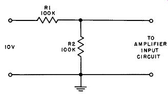
Fig. 10. Simple input voltage divider.
... resistor R2 in the circuit shown in Fig. 10. When the amplifier is not connected in the circuit, it will be seen that 10 volts is applied across the two series resistors (R1 and R2) to ground. Since the value of each resistor is 100,000 ohms, the voltage developed across R2 = 10[R2/(R1 + R2)] = 10[10^5/(10^5 + 10^5)] = 5 volts, which is the desired value.
However, when the amplifier input circuit is connected across resistor R2, this resistor is shunted by the amplifier input impedance, and the effective resistance ( Re) of these parallel resistors is equal to R1 R2/(R1 + R2) = (10^5) (2.5 x 10^4) /(10^5 + 2.5 X 10^4) = 20,000 ohms. Under these conditions the voltage developed across this effective resistance (which is the voltage supplied to the amplifier input circuit) is no longer 5 volts, but is reduced to 10 [Re/(R1 + Re)] = (2 X 10^5) /(10^5 + 2 X 10^4) = 1.67 volts.
This is often an unacceptably low value.
However, when inverse feedback is used in such a manner that the feedback voltage is in series with the input voltage, and the feedback factor is chosen to have a value of 100, the input impedance in the presence of feedback (which, as indicated previously, is equal to the input impedance in the absence of feedback multiplied by the feedback factor), will be equal to 25,000 (100) or 2.5 megohms. The effective resistance under these conditions is equal to (10^5) (2.5 x 10^6)/(10^5 + 2.5 x ]06) or approximately 96,000 ohms. As a result, the input voltage will be (9.6 X 10^4) / (10^5 + 9.6 X 10^4) or approximately .49 volt. Thus the input voltage is maintained very close to its proper value.
As a further example, assume that an amplifier is coupled at its output circuit to a long transmission line, and that the output impedance of the amplifier without feedback is 35,000 ohms, while the input impedance of the transmission line is 350 ohms.
In order to hold power losses to a minimum, the output impedance of the amplifier should be approximately equal to the input impedance of the transmission line. Here there is a 100-to-1 ratio between the amplifier output impedance and the transmission line input impedance and, obviously, there will be a substantial power loss.
If inverse feedback is used in the manner shown in Fig. 8, and a feedback factor of 100 is used, the amplifier output impedance will be 35,000/100 or 350 ohms, and the desired impedance relations arc established.
19. QUIZ
(1) What is meant by impedance matching?
(2) What is the effect on amplifier input impedance when the feedback voltage is in series with the input signal?
(3) What is the effect on amplifier input impedance when the feedback voltage is in parallel with the input signal?
(4) What is the effect on amplifier output impedance when current feedback is used?
(5) What is the effect on amplifier output impedance when voltage feed back is used?
(6) How is the amplifier output impedance affected by the use of bridge feedback?
(7) Explain the effect when the feedback voltage is in parallel with the input signal.
(8) Explain the effect when the feedback voltage is in series with the input signal.
(9) In what manner does bridge feedback modify the amplifier input impedance as compared to current and voltage feedback?
(10) When the output of an amplifier is connected to a transmission line, what is the advantage in using negative feedback?