AMAZON multi-meters discounts AMAZON oscilloscope discounts
20. Phase Relations in the Absence of Feedback
The gain of any amplifier varies at least a little with the frequency of the incoming signal. This variation of gain with frequency is due to the presence of inductive and capacitive reactances in the amplifier. These reactances not only alter the amplitude of the output signal and voltage with frequency (when a constant amplitude signal of variable frequency is used as an input signal), but also shift the phase of this voltage. As we shall see, this phase shift is extremely important in inverse feedback applications. however, in order to understand the action of amplifier phase shift in the presence of feedback, it is necessary to understand the action of amplifier phase shift when no feedback is present.
One of the simplest and most common cases of phase shift occurs with the circuit shown in Fig. 11. When an incoming a-c voltage is applied between the left hand terminal of the resistor and ground, an output voltage will be produced across the capacitor. For a given value of resistance and a given value of capacitance, the reactance of the capacitor will decrease as the frequency of the incoming voltage increases. (It will be recalled that the capacitor reactance is equal to ½ pi fC when f is the frequency of the incoming voltage and C is the capacitance of the capacitor.) Thus, as the frequency is increased, a point will be reached at which the capacitor reactance approximates zero, and virtually no voltage will be developed across the capacitor. Thus this circuit acts as a low pass filter that cuts off at frequencies high enough to cause the capacitor reactance to approach zero.
This circuit also shifts the phase of the voltage developed across the capacitor with respect to that of the incoming voltage.
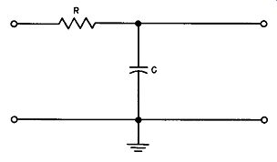
Fig. 11. A circuit that causes phase shift (low pass filter).
This effect can best be understood by analyzing the circuit behavior as the frequency of the incoming voltage is varied. When this voltage has zero frequency (that is, the voltage is steady d-c) , the capacitor charges to the steady de value after a time fixed by the ratio of the resistance to the capacitance. As frequency increases, the capacitor charges to its maximum value at a later time than that at which the incoming voltage attains its maximum value, and the capacitor voltage lags the incoming voltage. Thus a lagging phase shift is produced.
As the frequency of the incoming signal is further increased, the amount of phase shift increases and approaches 90 degrees as a theoretical limit. A plot of this shift against frequency for a practical circuit with typical component values is shown in Fig. 12.
For those interested, the mathematical expression for the phase angle (theta ) is given in this figure.
The circuit shown in Fig. 13 also acts as a low pass filter. The reactance of the coil is equal to 2 pi f L, where f is the frequency of the incoming signal and L is the inductance of the coil. Thus, as the frequency of the incoming signal increases to relatively high values, the reactance of the coil becomes so large relative to the resistance of the resistor that the voltage developed across the resistor becomes negligible. At this point, of course, there is virtually no output voltage.
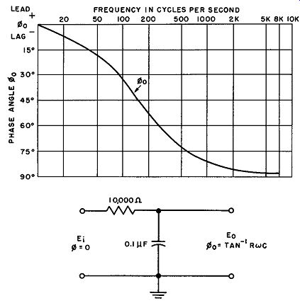
Fig. 12. Phase shift characteristic of a typical low pass filter circuit.
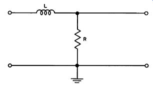
Fig. 13. Another phase shifting circuit, also a low pass filter.
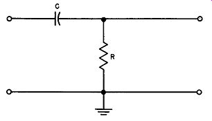
Fig. 14. High pass filter phase shifter.
It will be recalled that the voltage across an inductance leads the current flowing through it by 90 degrees. For high frequencies, substantially all of the impedance appears across the coil. The current through the combination therefore lags the applied voltage by almost 90 degrees. Thus, the small output voltage developed across the resistor must also lag the input voltage by almost 90 degrees (assuming that the load has no effect). As the signal frequency decreases, this lagging phase shift decreases. In other words, the circuits of Fig. 11 and Fig. 13 behave in similar fashion.
Consider the circuit shown in Fig. 14. When an incoming voltage is applied between the left hand terminal of the capacitor and ground, an output voltage will be produced across the resistor. As the frequency of the incoming signal is decreased, the resistor and capacitor having fixed values, the reactance of the capacitor will increase. Consequently, a point will be reached at which virtually all the incoming voltage will be applied across the capacitor, and virtually no voltage will be applied across the resistor. Thus this circuit acts as a high pass filter; it will not pass frequencies low enough to cause the voltage across the resistor to approach zero.
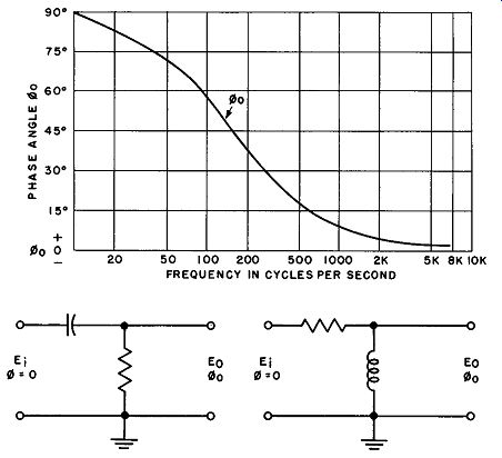
Fig. 15. Leading phase shift produced by high pass filter.
It will be recalled that the current flowing through a capacitor leads the voltage produced across it by 90 degrees. Thus, in the circuit shown in Fig. 14, if dc (zero-frequency) voltage is suddenly applied at the input, the voltage across the resistor is initially a maximum and decreases toward zero as the capacitor charges to its maximum value. Thus the voltage across the resistor leads the incoming voltage by nearly 90 degrees. As the frequency of the incoming voltage increases, this phase shift decreases, but it remains a leading phase shift. A plot of this shift against frequency is shown in Fig. 15. Note that the shape of the curve is exactly like that of Fig. 12, but here the phase is leading and starts at 90 degrees, falling off to near zero at high frequencies.
A resistance-inductance network can also be used as a high pass filter, as shown in Fig. 16. As the signal frequency decreases, the reactance of the coil decreases until, at low frequencies, most of the voltage of the circuit is developed across the resistor. There is very little voltage produced across the coil; hence there is no output voltage.
The current in the coil lags behind the voltage developed across it, and the voltage across the resistor is in phase with the current flowing through it. At low frequencies virtually all the input voltage appears across the resistor, and the current flowing through the resistor is in phase with the input voltage. This same current flows through the coil, and therefore the very small voltage developed across the coil leads the current by almost 90 degrees.
Consequently, this small voltage leads the input signal by the same approximate 90-degree phase shift. As the signal frequency increases, the amount of shift decreases, but it remains a phase lead.
Thus the circuits of Figs. 14 and 16 function in the same manner, and both develop a leading phase shift.
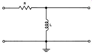
Fig. 16. An inductive high pass filter.
To summarize, in a low pass filter, high frequency cutoff causes a phase lag in the output voltage relative to the input voltage, while in a high pass filter, low frequency cutoff causes a phase advance in the output voltage relative to the input voltage. The amplitude and phase relations in the four simple filter circuits discussed are summarized in Fig. 17.
Since almost every amplifier contains one or more high pass and low pass filters (even though not always referred to as such), it will be seen that a phase shift between amplifier input and output voltage can readily be produced, and further that the amount of phase shift can vary with frequency.
21. Frequency Response in the Absence of Feedback
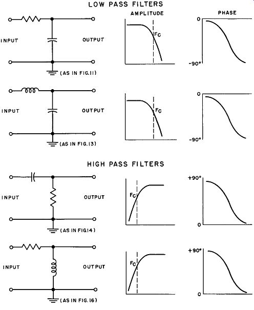
Fig. 17. Summary of characteristics of simple high and low pass filters.
Amplifiers having one or more of these filters will not respond well to signals of frequencies beyond cutoff. When an amplifier will not respond to frequencies above and below a certain range, while passing all frequencies falling within the range, it is said to have a frequency bandwidth or frequency bandpass characteristic defined by the lowest and highest frequencies that can be passed.
When an incoming signal of a fixed amplitude is supplied to an amplifier having a given bandwidth, and the signal frequency is varied within this band, it will be found that (as indicated in the previous section) the gain of the amplifier is not fixed, but varies with frequency. This variation is called its frequency response. Figure 18 is a graph of the frequency response of a typical audio frequency amplifier.
22. Effect of Feedback on Phase and Frequency
In inverse (negative) feedback the incoming signal and the feedback voltage always oppose each other. For a-c signals, this is equivalent to stating that the incoming signal and the feedback voltage are always opposite in phase. In the case of d-c signals, they are op posed in polarity. However, because of the phase shifts between amplifier input and output voltages caused by frequency cutoff characteristics, it will be seen that the feedback voltages can also shift in phase. This is the same as saying Beta has a phase angle other than zero, or A has a phase angle other than zero or 180 degrees. This shift can be so great as to convert inverse feedback into positive feedback (in which case the feedback voltage will act in phase with the incoming signal) . At this point, the gain of the amplifier with feedback will be in excess of the gain without feedback and the amplifier may even oscillate. Consequently, in verse feedback is not always a cure-all, and careful analysis of the circuitry in which it is to be used is necessary before inverse feed back can be used successfully.
The discussion thus far has indicated that, for a given value of the input signal and a given amplifier gain, the feedback voltage will have a fixed value. As indicated previously, however, the gain of an amplifier varies with frequency so that, when the amplitude of the incoming signal is held constant but its frequency is varied, Fig. 18. Shape of frequency response characteristic of typical a-f amplifier, the amplitude of the feedback signal will vary with frequency. The net result is that the gain of an amplifier employing inverse feed back is not necessarily held constant over a given frequency range.
One approach to overcoming these phase and frequency limitations in inverse feedback is to design the feedback network to adjust its phase and frequency response with respect to the phase and frequency response of the amplifier in such a manner that the feedback voltage is automatically adjusted to have the proper phase and amplitude relative to the incoming signal.
For example, suppose that at a given frequency, the amplifier output voltage lags the amplifier input signal by 45 degrees, so that the feedback voltage would be shifted 135 degrees with respect to the input signal instead of the desired 180-degree shift. If the feedback network is designed at this frequency to cause the feed back voltage yielded by the network to lead the amplifier output voltage by 45 degrees, the desired 180-degree shift in feedback voltage can be obtained.
Similarly, if the amplifier gain is reduced at a particular frequency, the feedback network can be designed to have a like increase at this frequency, so that the feedback voltage can be maintained at its proper value. [1]
The bandwidth of an amplifier is normally defined as the number of frequency units between the points at which the response characteristic falls below 0.707 times the response (gain) in the middle-frequency range. The response above and below these points does not drop sharply below the 0.707 value, but tapers off. In the amplifier with feedback, the feedback voltage is greatest whenever the gain is greatest, which is the value in the middle portion of the response characteristic. Therefore, in this range, the full effect of feedback in lowering the gain is experienced. However, at frequencies just beyond the 0.707 points, feed back falls off with gain, so the overall gain is not lowered as much.
The lower the amplifier gain, the less reduction it suffers from feedback. There is thus a marked "flattening effect" on the response, and the 0.707 response points are pushed further apart. Accordingly, the bandwidth of the amplifier is substantially increased.
Through the use of feedback, the gain of the amplifier can be limited to small values over substantially the entire bandwidth.
Thus the effective bandwidth can be extended to conform substantially to the bandwidth defined by the high and low cutoff frequencies of the amplifier.
23. Effect of Feedback on Stability
When an amplifier oscillates or tends to oscillate at one or more frequencies, it is said to be unstable at these frequencies. An amplifier without feedback can be unstable, particularly when re sonant circuits cause the amplifier gain to peak sharply at certain frequencies.
1. For detailed information on the design of feedback networks, see Hendrik W. Bode, Network Analysis and Feedback Amplifier Design (New York: D. Van Nostrand Co., Inc., 1945).
Consequently, when inverse feedback is properly used, the amplifier gain can be maintained at such a value that it is insufficient to cause oscillation. In this manner, use of inverse feedback can improve the stability of an amplifier.
As described previously, however, phase shifts can convert in verse feedback into positive feedback, thus making an amplifier less stable than without feedback. A designer, if he so chooses, can make a series of calculations and determine what phase shifts are developed in an amplifier for each signal frequency under consideration, and thus design his amplifier circuitry so that inverse feedback will serve its proper purpose over the frequency range desired. Such calculations are extremely tedious and time consuming, so that other more rapid methods are normally used. One such method is called a Nyquist diagram. This method is highly mathematical and will not be described in detail here. However, the Nyquist diagram is a graph on which the quantity - Beta A is plotted against frequency in such a manner that it is possible to determine amplifier stability at any particular frequency by reading values off the graph.
24. QUIZ
(1) Why does the gain of an amplifier vary with frequency?
(2) What is high frequency cutoff? A low pass filter?
(3) What is low frequency cutoff? A high pass filter?
(4) What is the effect of high frequency cutoff on the direction and magnitude of phase shift?
(5) What is the effect of low frequency cutoff on the direction and magnitude of phase shift?
(6) What is meant by the term "frequency bandpass characteristic?"
(7) Why is phase shift important in inverse feedback applications?
(8) Can the band width of an amplifier be broadened through the use of feedback?
(9) What is meant by amplifier instability?
(10) What is a Nyquist diagram?