AMAZON multi-meters discounts AMAZON oscilloscope discounts
25. Feedback Loops
The combined amplifier and feedback circuit shown in Fig. 1, which extends from the amplifier input through the amplifier and feedback network back to the amplifier input, is called a feedback loop. Since one amplifier stage and one network are used, this arrangement is defined as a single-stage single-feedback loop.
When one amplifier stage is used in conjunction with two or more feedback networks in the manner described in more detail later in this Section, the resulting circuit has as many feedback loops as there are feedback networks. Such an arrangement is termed a single-stage multi-loop feedback circuit.
When one feedback network is used in conjunction with two or more amplifier stages, again in a manner described in more detail later, the resulting circuit has as many stages as there are amplifier stages. Such an arrangement is termed a multi-stage single-loop feedback circuit.
In order to understand how multi-stage and multi-loop feed back circuits function, it is necessary to analyze single-stage single Jeep feedback systems in more detail.
Figure 19 shows a typical triode amplifier circuit incorporating one stage of amplification and one voltage feedback network.
An incoming alternating signal is applied through blocking capacitor C1 between the grid of a single triode V1 and ground. The plate of the tube is connected through a load resistor RL to the positive terminal of a battery (B1). The negative terminal of the battery is grounded. The cathode of the triode is connected to ground through a cathode resistor, R. The cathode resistor is shunted by a bypass capacitor, Ck· The plate of V1 is connected through a blocking capacitor (Cr) and a feedback resistor (Rr) back to the grid. The cathode resistor and capacitor serve to produce cathode bias in the usual fashion.
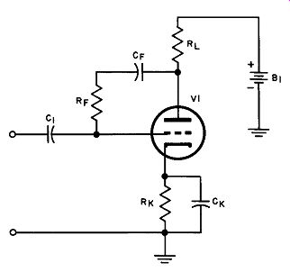
Fig. 19. One stage amplifier with single feedback loop.
This circuit operates in the following manner. As the alternating signal increases in amplitude, the current flow through the " tube increases, the voltage drop across the load resistor increases, and the plate of the tube becomes less positive. As the plate potential decreases, this decrease is fed back through capacitor Cr and feedback resistor Rr to the grid as a feedback voltage in series with the incoming voltage. This voltage acts in opposition to the in coming signal, and hence is an inverse feedback voltage.
Conversely, when the alternating signal decreases in amplitude, the current flow through the tube decreases, the voltage drop across the load resistor is decreased, and the plate of the tube be comes more positive. As the plate potential increases, this increase is fed back to the grid as an inverse feedback voltage in the same manner as before.
Now, if the circuit of Fig. 19 is modified by removing capacitors Cr and C~, and resistor Rr, as shown in Fig. 20, it will be seen that the resulting circuit incorporates one stage of amplification and one current feedback network.
Since the cathode bypass capacitor has been eliminated, all a-c voltages previously shunted around the cathode resistor by its bypass capacitor now flow through the cathode resistor. As the instantaneous voltage of the incoming signal increases, the instantaneous current through the cathode resistor increases and the positive cathode voltage increases. Similarly, when the instantaneous voltage of the incoming signal decreases, the instantaneous current through the cathode resistor decreases and the positive cathode voltage decreases. The positive voltage on the cathode with respect to ground (and thus also with respect to grid) is also a negative voltage on the grid with respect to cathode. Thus the changes in cathode voltage act in an inverse sense compared to the change in the incoming signal, so that an inverse current feed back effect has been developed.
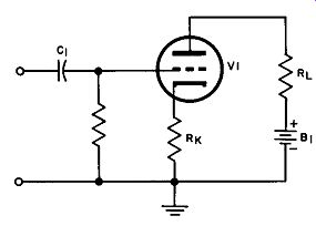
Fig. 20. One stage amplifier with one current feedback loop.
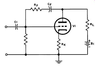
Fig. 21. Single stage, double loop circuit.
26. Single-Stage Multi-Loop Feedback Circuit
The inverse voltage and current feedback systems shown in Figs. 19 and 20 can be combined into a single-stage double-loop feedback circuit, as shown in Fig. 21.
Current feedback takes place in the same manner as indicated in Fig. 20, while voltage feedback takes place in the same manner as in Fig. 19. This arrangement is similar to the bridge feedback arrangement described in Section 1, and functions in the same manner.
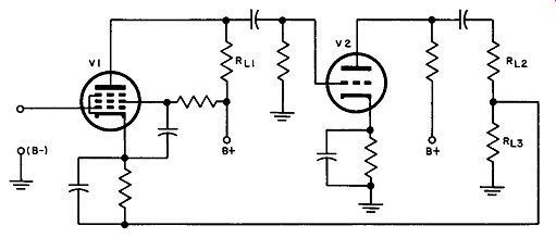
Fig. 22. Multi-stage, single loop arrangement.
27. Multi-Stage Single-Loop Feedback Circuit
In order to change the amount of feedback, the feedback factor must be changed. For example, if the amount of feedback is to be increased, either the feedback fraction (~) or the amplifier gain in the absence of feedback (A), or both A and ~ must be increased. The feedback fraction can be changed by suitable design of the feedback network, but since this fraction is virtually always less than l, the total change produced in this manner is limited.
However, the amplifier gain can be increased either by increasing the gain in an amplifier stage or by using additional stages.
When several stages of amplification are required, circuits similar to that shown in Fig. 22 can be used. This arrangement includes a pentode tube (V1) and a triode tube (V2). When an in coming alternating signal is supplied to the grid circuit of the pentode, the signal is amplified in the pentode and appears in amplified form across the load resistor (Rr, 1) of this tube. The amplified signal is then supplied to the grid circuit of the triode (V2 ). This signal is further amplified in the triode and appears in amplified form across the load resistors (Ru and RL3) of tube V2. The portion of the amplified signal that appears across RL.~ is returned as a feedback signal to the cathode of the pentode V1.
The mid-frequency amplified signal appearing at the plate circuit of any ordinary resistance-coupled tube is 180 degrees out of phase with the signal applied to the input circuit of the tube.
Since two successive tubes are used in this circuit, the signal sup plied to the grid circuit of tube (V1) is shifted 180 degrees by the action of the tube V1 and is shifted by the action of tube V2 an additional 180 degrees. The total amplification (A) is thus positive.
Consequently, the feedback voltage is in phase with the incoming signal. However, the incoming signal is supplied to the grid of tube V1, while the feedback voltage is supplied to the cathode of this tube.
Thus, as the instantaneous voltage of the incoming signal increases, the cathode voltage of tube V1 is increased, and the action of the feedback voltage opposes that of the incoming signal to provide the desired inverse feedback relation.
If an additional amplifier tube is coupled to the output of tube V2, and the feedback voltage is derived from the plate circuit of the additional tube, the feedback voltage will be shifted an additional 180 degrees with respect to the incoming signal. In this event, the feedback voltage Will be 180 degrees out of phase with the incoming signal, and to provide inverse feedback the feedback voltage and the incoming signal must both be applied to the grid of tube V1.
28. Inverse Feedback in Push-Pull Amplifiers
When a push-pull amplifier does not make use of inverse feed back, the two tubes that provide the push-pull operation must have matched characteristics and must be balanced in the circuit to provide identical amounts of gain. Otherwise, the amplifier output signal will not have the same waveshape and amplitude over each half of the signal cycle, and the amplifier output signal will be appreciably distorted. It is not always easy to provide such matched tubes. In addition, as the tubes age their characteristics can change in different ways so that the tubes will no longer be
matched. Furthermore, as the circuit components age and change values, the circuit balance can be upset. The net result is impaired signal fidelity.
However, as indicated in Section 1, when large amounts of in verse feedback are used in an amplifier, the amplifier gain depends only on the feedback fraction and is substantially independent of the gain of the amplifier in the absence of feedback. Therefore, when large amounts of inverse feedback are used in a push-pull amplifier and the feedback factor is the same for both tubes, the gains provided by these tubes can be adjusted to the same value even though the tube characteristics vary and the circuit components change value.
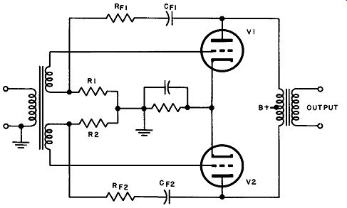
Fig. 23. Push pull circuit with inverse feedback.
Figure 23 shows a push-pull amplifier circuit in which inverse feedback is used. A feedback network, consisting of a blocking capacitor (C1) and a resistor (R1) in series, is connected between the plate of tube V1 and the ungrounded end of grid resistor R1. The voltage produced at the plate of V1 is 180 degrees out of phase with the incoming signal supplied to the grid of V1. Since a portion of this voltage is impressed as a feedback voltage across the grid resistor, the feedback voltage and the incoming signal are sup plied in phase opposed to the signal voltage at the grid of tube V1, thus inverse feedback is developed.
An identical feedback network is connected in the same manner in the circuit of tube V2, and inverse feedback is developed in a similar fashion. By increasing the value of the grid resistor relative to that of the resistor in the feedback network, the magnitude of the feedback voltage produced across the grid resistor is increased; a suitable ratio of these two resistor values will provide a sufficiently large amount of feedback to cause the gain of each tube to be dependent only upon the feedback fraction.
Essentially, a push-pull amplifier using inverse feedback can be regarded as a single-stage double-loop feedback circuit.
29. Effect of Feedback upon the Stability of Multi-Loop and Multi-Stage Circuits
When a multi-loop single-stage amplifier is used, the phase and frequency relationships must be carefully analyzed for each feed back loop in the manner described in Section 3. However, this type of amplifier is normally more stable than a single-stage single-loop amplifier because, even if positive feedback is provided in one loop, the inverse feedback provided by the other loops is normally sufficient to hold the amplifier gain at a level below that required for oscillation.
The single-loop, multi-stage amplifier circuits, on the other hand, tend to be less stable than the single-stage single-loop circuit. Each amplifier stage, of course, contains high and low pass filters, which introduce phase shift. The shifts produced in each stage are added together to produce an overall phase shift in the particular multi-stage circuit used. Therefore, even though the phase shifts in any one stage may be insufficient to convert feed back to positive feedback, the cumulative effect of the shifts produced in each stage may do so.
Since the cumulative effect of phase shift increases as the number of stages is increased, negative feedback is normally not used around more than three stages. In most cases only two stages are used.
When inverse feedback is used in push-pull amplifiers, great care must be taken to insure that both feedback loops behave in an identical fashion. If the two loops are not adjusted properly, the halves of the circuit can become unbalanced, and the amplifier will not behave properly. As long as the phase shifts in each loop are analyzed properly, however, even though the tubes are unbalanced, the amplifier will not oscillate, and will remain stable.
30. QUIZ
(1) What is a feedback loop? (2) What is a single-stage multi-loop feedback circuit? (3) What is a multi-stage single loop feedback circuit? (4) What is the special advantage of using inverse feedback in push-pull amplifier circuits? (5) What is the effect of amplifier phase shift in multi-stage inverse feedback applications? (6) How is current feedback produced in a single-stage amplifier circuit when no cathode bias capacitor is used? (7) What is the advantage of using more than one stage in a feedback amplifier? (8) What is the advantage of using more than one feedback loop? (9) How does current feedback to an unbypassed cathode resistor produce an inverse feedback relation? (10) Why is negative feedback normally used around a maximum of three stages?