AMAZON multi-meters discounts AMAZON oscilloscope discounts
There are literally hundreds of different types of circuits in which inverse feedback is used. The circuits described in the remaining portion of this Section are well known and widely used, but can represent only a few of the many applications of feedback.
31. Cathode Followers
The cathode follower is basically an amplifier in which inverse feedback is obtained by means of an unbypassed cathode resistor which also serves as an output load resistor. The output voltage is produced across this cathode resistor. The cathode follower has a high input impedance and a very low output impedance, and for this reason is often described as an impedance transformer. Its voltage gain is always less than one, but generally, the output power is at a much higher level than the power carried by the input signal.
One very important use of the cathode follower is found in highly complex electronic equipment where a signal must be trans mitted along a transmission line for a considerable distance (often as much as 100 feet or more). A transmission line normally represents a low impedance, and thus the low impedance output of the cathode follower is ideally suited for supplying maximum power to such a line.
A conventional cathode follower circuit is shown in Fig. 24.
It is a single-stage single-loop inverse feedback circuit in which the output voltage is taken across the cathode resistor, Rk. There is no cathode bypass capacitor. The plate of the tube, which in this example is a triode, is usually connected directly to B+. If a plate load resistor is used, this resistor is bypassed by a capacitor.
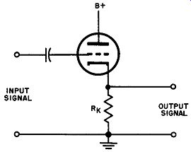
Fig. 24. Conventional cathode follower.
When a positive signal voltage swing is supplied to the grid, the plate current increases, and the voltage drop across the cathode resistor increases. Similarly, a negative signal voltage swing reduces the plate current and the voltage developed across the cathode resistor decreases. Thus the voltage across the cathode resistor "follows" the grid voltage. This tends to reduce the voltage difference between grid and cathode (and hence the amplifier gain) established by the input signal alone.
Because of the particular action just explained, the output voltage is in phase with the input signal. This, of course, is not the situation in a conventional amplifier when the output voltage is 180 degrees out of phase with the input signal.
32. The Williamson Amplifier
The Williamson amplifier is a well known high fidelity audio amplifier utilizing inverse feedback. It is essentially a multi-stage single-loop feedback circuit having a push-pull power amplifier stage.
As shown in Fig. 25, the incoming signal is successively amplified in the V1 and V2 triode sections of a 6SN7 dual triode. This amplified signal is then supplied to the V3 and V4 sections of a second 6SN7 dual triode. This second tube serves as a phase splitter to produce two amplified output signals that are opposed in phase.
These two signals are then supplied as push-pull input signals to a push-pull power amplifier stage employing two 1614 pentodes.
A transformer couples the common output circuit of the 1614's to a loudspeaker. The feedback voltage is derived from the secondary winding of the transformer and is supplied to the cathode of the V1 section of the first 6SN7 dual triode as an inverse feedback voltage.
The voltage developed across the secondary winding of the transformer is 180 degrees out of phase with the voltage supplied to the primary winding. By tracing through the circuit it will be Fig. 25. The Williamson Amplifier circuit.
found that the feedback voltage has the proper phase relation with respect to the incoming signal to provide the necessary inverse feedback relation. Of course, feedback can be obtained in either polarity, according to the winding sense of the output transformer and the choice of which end of the secondary is grounded.
This action is similar to that described in the multi-stage single loop circuits discussed in Section 4.
33. Bass Boost Feedback Amplifier
When a constant level input signal of variable frequency is supplied to a loudspeaker, it will be found that the sound power developed in the speaker at low frequencies is less than the power developed at higher (middle) frequencies. This is a result of limitations inherent in the speaker.
In order to compensate for this reduction in power at low frequencies, the amplifier supplying power to the loudspeaker is often designed to provide higher gain for low frequency signals than for mid-frequency signals. As a result, the low frequency loss in the speaker is overcome by the low frequency boost in the amplifier.
One popular method of adjusting amplifier gain in this fashion is to make use of inverse feedback. In this application, the amount of feedback used at low frequencies is less than the amount of feed back at higher frequencies. Thus the amplifier gain, though al ways reduced by inverse feedback, is reduced to a smaller degree for low signal frequencies than for higher frequencies.
A typical circuit of this type is shown in Fig. 26. This circuit is essentially a two-stage dual-loop feedback amplifier.
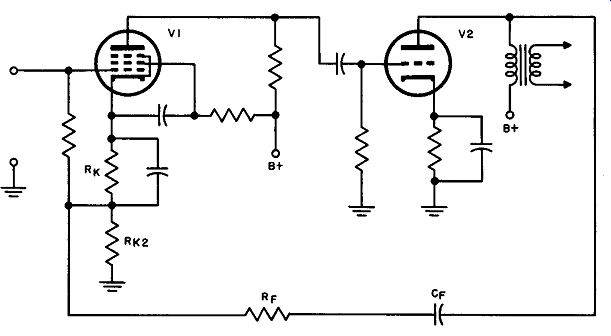
Fig. 26. Two stage dual feedback loop system.
An incoming signal is amplified in tube V1 and again in tube V2. The amplified output voltage appearing at the plate of tube V2 is fed back through capacitor C1 and resistor R1 to the junction of resistors RK1 and RK2. (The amplified voltage is an inverse feedback voltage because the feedback voltage is in phase with the incoming signal, and is fed to the cathode instead of the grid of tube V2. This relationship is discussed in more detail in Section 4.)
Capacitor C1 has a high reactance at low frequencies and a low reactance at high frequencies. The portion of the output voltage that is supplied to the cathode of tube V1 decreases as the frequency is lowered and capacitor reactance increases. Consequently, the feedback voltage reduces the low frequency gain of the amplifier to a smaller extent than the mid-frequency gain, and the desired amount of bass boost is obtained.
Since resistor RK2 is not bypassed by a capacitor, a small amount of negative current feedback is also present in the V1 amplification stage. This current feedback, however, does not vary with frequency (except in proportion to gain) and serves only to provide an additional constant amount of inverse feedback, which tends to increase the stability of this circuit. However, as previously pointed out, even simple negative feedback tends to increase bandwidth.
34. Direct Current Vacuum Tube Voltmeter Using Inverse Feedback
The circuit shown in Fig. 27 is a dc amplifier using current feedback. It is designed for a dc measuring instrument and is somewhat unusual in that it utilizes almost 100 percent feedback.
(In other words, the feedback factor is approximately 1.) The incoming dc signal is amplified successively in three amplification stages, each stage using a 1B4 pentode. This type of tube has a directly-heated emitter. The output current flowing in the output amplifier stage passes through a parallel circuit consisting of a 10,000-ohm output resistor shunted by a voltmeter (V) and potentiometer (P) in series (a 1.5-volt battery is connected across the potentiometer) and is supplied thereafter to the emitters of the three paralleled 1B4's.
When the incoming signal becomes more positive, the amplified current in the output of the first 1B4 increases, causing the plate of the first IB4 to become more negative. Thus the amplified current in the output of the second 1B4 decreases, and the amplified current in the output of the third 1B4 increases. This output current flows through voltmeter V, resulting in a voltage drop across V. This drop makes the cathodes of all the tubes more positive, thus decreasing the amplification for each stage and pro viding the necessary amount of inverse feedback.
The resistance of the voltmeter is on the order of 1000 ohms compared to the 10,000-ohm output resistor, so that very little current flows through the output resistor, and virtually all of the output current passes through the voltmeter to the cathodes as a feedback current.
In operating this voltmeter, the input terminals are short circuited and the potentiometer is adjusted until voltmeter V reads 0. These terminals are than opened and the input signal applied in the usual manner. The magnitude of the unknown d-c voltage applied to the input terminals is then given directly by the reading on the voltmeter.
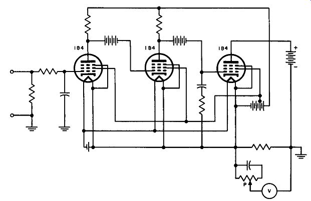
Fig. 27. A dc amplifier circuit using current feedback for making dc measurements.
This result is obtained because the voltmeter deflection measures the feedback signal and for large amounts of feedback, the feedback signal and the incoming signal are approximately equal.
Thus, although gain is not much better than 1, the amplifier is a stable matching device between the high impedance input and the relatively low impedance meter.
35. Use of Feedback on Automatic Volume Control Circuits
It will be recalled that in a conventional a-m radio receiver an incoming carrier wave of given frequency, amplitude-modulated by an audio signal, is amplified, then heterodyned with a voltage from a local oscillator to produce a carrier of lower fixed (intermediate) frequency, but having the same modulation envelope as the incoming carrier wave. The carrier thus produced by the heterodyning operation is amplified in an intermediate frequency amplifier and then detected in a detector to recover the original audio signal. This audio signal is amplified and supplied to a loudspeaker.
Virtually all such receivers are provided with an automatic volume control circuit (ave) to maintain the carrier wave voltage supplied to the input of the detector at an approximately constant level. As a result, when the strength of the received signal varies due to fading, or when the receiver is tuned from weak to strong stations, the volume of the signal reproduced in the loudspeaker will not change appreciably. Accordingly, the volume control of the receiver does not have to be adjusted as frequently as in receivers without ave.
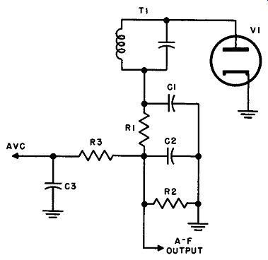
Fig. 28. Typical ave network.
The ave action is obtained by supplying a portion of the voltage produced at the output of the detector as an inverse feedback voltage to the input circuits of the various stages preceding the detector. In this manner, as the strength of the incoming carrier changes, the gain of these stages is changed in opposite sense and the carrier strength is held approximately constant. This action is sometimes called feedback. However, since the "signal" fed back is not in the same form as the input signal, it differs from types previously discussed.
There are many different types of ave circuit. Figure 28 shows one of the simplest of these.
The output signal from the intermediate frequency amplifier (developed across the primary winding of transformer T1) appears across the secondary winding of the transformer and is supplied to diode V1. This diode, together with an associated network composed of resistors R1 and R2 and capacitors C1 and C2, serves to produce the detected signal, which appears across resistor R2. The dc portion of the detected signal is then supplied through a low pass filter network containing resistor R3 and capacitor C3 back to the input circuits of the preceding stages in the manner indicated previously. (See Section 3 for further details on this type of network.) The low pass filter network is required because the purpose of ave is to control the strength of the carrier and not the strength of the modulation signal riding on the carrier. The modulation signal is a low frequency (audio) signal. It appears across R2 along with a dc component, and this network removes most of the audio frequency components. The "feedback voltage" is the remaining dc component. The low pass characteristic of R3-C3 is such that the inverse feedback voltage follows slow changes in the strength of the incoming carrier, such as those which might result from fading and tuning stations of different signal strength.
36. QUIZ
(1) What is a "cathode follower?"
(2) Why is a cathode follower often referred to as an impedance transformer?
(3) Why is the output voltage produced by a cathode follower in phase with the input voltage supplied to it?
(4) How is inverse feedback developed in the Williamson amplifier?
(5) How can inverse feedback be used to vary amplifier gain as the frequency of the amplifier signal changes?
(6) What is meant by automatic volume control?
(7) Why is ave action like inverse feedback?
(8) Why does the ave feedback loop require a low pass filter?
(9) Why does the dc measuring instrument shown in Fig. 27 use a feedback factor of approximately 1?
(10) What is the advantage of ave?