AMAZON multi-meters discounts AMAZON oscilloscope discounts
6. Fundamental Circuit
The basic bi-stable multivibrator circuit is illustrated in Fig. 3. As is evident from an inspection of the circuit diagram, each tube is an amplifier, the plate of which is directly coupled through a resistor to the grid of the other. The load resistances (RL) are much smaller in value than the coupling resistances (R1 and R2). Typical values are 15k ohms for the load resistors and 1 megohm apiece for the coupling resistors.
From the symmetry of the circuit one might suspect that the quiescent current in each tube would be the same. This is not the case, however, as will be shown in the following text; in addition, the starting state is an unstable condition, which almost immediately causes one tube to go off and the other to go on. Suppose there is a momentary increase of current IP1 in tube 1. This causes a negative voltage pulse to appear at the plate of V1. This negative pulse is immediately transferred to the grid of V2 through R1.
(See Par. 3.) As this grid goes more negative than previously as a result of this pulse, plate current IP1 of V2 decreases, causing a positive voltage pulse to appear at its plate. Since this plate couples to the grid of V2 through R2, a similar positive pulse instantaneously appears at this grid, further increasing plate current I_p1. Since it was just this effect that started the action, and since the effect is being intensified by repeated pulse transfer from tube to tube, it constitutes a runaway situation, which continues until either one of two things happens:
a. V2 may reach cutoff. In this case Eps becomes equal to the supply B+ voltage. (The voltage drop that occurs either in RL, as a result of the current flow from B- to B+ through RL, R2, R3, or through RL, R1, R4 is neglected in this discussion).
b. V2 may go full-on. Depending upon the supply voltages and the circuit parameters, one of these conditions will be attained. be fore the other; this will be the stable state, in which the circuit will remain. For example, if V2 is cut off, any momentary increase in I_p1 will only drive the grid of V2 further negative, causing no change in I_ps or Ep2. Similarly, if Ip1 should decrease slightly, its effect would be to make Eg2 somewhat less negative, but if the tube is sufficiently beyond cutoff, this will have no effect. An analogous argument may be used to show that, if one tube is full on, the circuit is also stable.
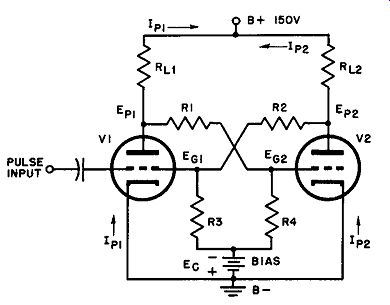
Fig. 3. Basic bi-stable multi-vibrator circuit.
7. Function of Bias Voltage
The statement in Par. 5 that a stable state cannot exist with both tubes carrying the same quiescent current must be qualified somewhat in this way: there are ranges of bias voltages for which both tubes may be full on or both tubes may be cut off. Except for these extreme conditions, however, the original statement still holds.
Taking specific component values for, say, a 6SN7 twin-triode: RL is 20k ohms, R1 and R2 are 1 megohm, R3 and R4 are 1 meg-ohm, and a supply voltage of 250 volts, it may be shown by analysis of tube behavior, as bias voltage is changed from zero to 280 volts or more, that there are actually five stable states (as tabulated in Table I).
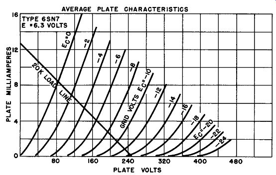
Fig. 4. Plate characteristics for the 6SN7GT, showing the load line for the
conditions in the circuit of Fig. 3.
How the five different stable states can exist may be better understood by remembering the following basic facts:
a. "Full-on" (as previously defined) is the state in which the net voltage on the grid is zero.
b. Net voltage on a grid is equal to the algebraic sum of the voltage coupled from the other tube plate and the bias voltage.
c. A tube remains "part-on" if its net grid voltage is more positive than the cutoff value, but more negative than zero.
d. A tube is "cut off" if it has enough negative grid voltage (net) to reduce the plate current to zero.
For illustration of how the values and conditions of Table 1 are obtained, consider the Ev - IP curves for the 6SN7 in Fig. 4. The plate load for each tube is 20k ohms, so a load line is drawn representing this value. It is drawn between the 250-volt plate voltage on the horizontal axis and 12.5 ma on the vertical axis. The current value is that resulting from application of the 250-volt plate voltage across the 20k ohm plate load. All possible conditions for each tube in this circuit fall along the load line thus drawn. Cutoff grid voltage is about -30 volts (cutoff is gradual). The following discussion of the five possible states can be checked against the graph of Fig. 4. Let us examine the conditions of Table 1.
a. Bias is between zero and 42 volts. Both tubes have a minimum plate voltage of about 84 volts, due to the drop across plate resistance of each during greatest conduction. This value is de rived by locating the point along the load line (Fig. 4) for zero grid volts (Ec = zero). Even when the coupled voltage from the other tube tends to be positive, the grid voltage stays close to zero, due to the flow of grid current through R3 and R4. Thus, until considerable bias is applied, neither tube can affect the other; they are both so far in conduction that even moderate changes of voltages cannot change this stable state.
b. When the grid is no longer positive (and thus does not shunt the grid resistor to low impedance) the voltage at a grid is about one-half the voltage of the plate to which it is coupled. This is because of the voltage-dividing action of coupling and grid resistors R2, R3 and R1, R4. When the external bias Ec is raised to about 42 volts (half the plate voltage of 84 volts) one of the tubes, being slightly different from the other, starts to have its current limited appreciably before the other tube. Let us say V2 plate current starts to become less. V2 plate voltage (and thus V1 grid voltage) becomes more positive. V1, still in the "full-on" condition, is not affected appreciably, maintaining about the same coupled voltage on the grid of V2. Thus no "runaway" condition occurs, V1 already being saturated. As bias is increased, current gradually de creases in V2, and V1 is full on while V2 is part on.
c. When bias E_c has been raised to 52 volts, it exceeds the positive voltage fed from V1 plate to V2 grid by enough to cut V2 off.
Further increases (up to 125 volts) keep V2 cut off and V1 full-on.
d. When the bias reaches 125 volts, it equals the portion of B+ voltage fed to V1 grid from V2 plate during cutoff of V2.
Then the net V 1 grid voltage starts to become negative and the plate current of V1 is reduced. With such a high bias, V2 cannot be pulled out of cutoff and further increase of bias simply reduces V1 plate current through the part-on condition.
e. When the bias reaches 140 volts, it exceeds the full B+ voltage coupled from V1 to V2 (125 volts) by enough to cut off VJ. Thus in this range (over 140 volts) both tubes remain cut off.
TABLE 1
Bias V1 V2
zero to 42 volts full-on, full-on
42 to 52 volts full-on, part-on
52 to 125 volts full-on, cut off
125 to 140 volts part-on, cut off
more than 140 volts cut off, cut off
Of course, since the circuit is symmetrical, the two right-hand columns may be interchanged to apply to either of the two tubes.
It is further evident from the table that careful consideration must be given to the choice of the bias voltage on the basis of tube type and circuit values if the circuit is to be truly bi-stable; i.e., one tube full-on and the other cut off.
8. Trigger Action of the Bi-Stable Multivibrator
In considering the stability of the circuit in Par. 6, it was pointed out that small spurious changes in current were ignored by the multivibrator. However, if a large positive pulse is intentionally injected into the grid of the cutoff tube, instantaneous plate current flows in this tube and a new runaway process begins, in which the conditions of the two tubes interchange. This is known as a transition and is explained in exactly the same way as was used to show why a "part-on, part-on" condition is not possible. Referring again to Fig. 3, assume that V 1 is cut off and V2 is full-on. A positive pulse is now applied to the grid of V 1, driving it into conduction. As its plate current rises, a negative pulse is transferred from its plate to the grid of V2, causing the plate current of V2 to drop; again, as a result of this decrease of I_p a positive pulse is transferred from the plate of V2 to the grid of V 1, causing it to rise further above cutoff. As in the previous case, the process is cumulative and results in a transition.
The action just described accounts for the name "trigger circuit." In most applications it is desirable to have a large change in voltage at the plate of one tube upon the injection of a pulse.
Hence the circuit is usually designed so that, in the quiescent state, one tube is full-on and the other is cut off, as explained previously.
The term bi-stable refers to this state and to its companion with the conditions of the tubes interchanged.
9. Self-Biased Bi-Stable Multivibrator
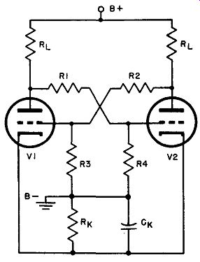
Fig. 5. Bi-stable multivibrator, circuit in which the external bias supply
is eliminated by use of cathode bias resistor R k.
The bias supply of Fig. 3 may be eliminated by using self-bias (Fig. 5) . The cathodes are tied together and returned to ground through a common resistor, Rk. If the two halves of the circuit were absolutely identical, the voltage drop across Rk would remain constant and there would be no need for a bypass capacitor. Assume, however, that the on current of V1 is greater than the on current of V2 because of different tube characteristics or differences in the resistors. Then, as the transition occurs, the rise of current in one tube is greater or smaller in rate than that of the other, causing degenerative action, which tends to slow down the transition. It is advisable to bypass Rk with a capacitor that will give a time constant consider ably higher than the transition time. Experience indicates that if the product of RkCk equals 100 microseconds, it is ample; thus, if Rk is 10k ohms (a normal value), Ck may be 0.01 µ.f.
The operation of the self-biased circuit is identical to that of the separately (fixed bias) biased arrangement of Fig. 3. The self biased circuit does have two distinct advantages, however: (a) no separate bias battery or supply is required, and (b) the quiescent conditions are less dependent upon individual tube characteristics, due to the "automatic" biasing action of Rk.
A design procedure for a self-biased, bi-stable multivibrator will be given later in this section.
10. Simultaneous Application of Pulses to Both Grids
In many applications, a succession of triggers is applied simultaneously to both grids. This is done by connecting the grids together by means of small capacitors (25 to 100 µµf.) and applying the trigger pulses to the junction point of the capacitors (Fig. 6). A positive trigger has no effect upon the on tube but will start the off tube drawing current to begin the runaway action and resultant transition. Assuming that there is an incoming train of positive pulses, the next one trips the new off tube to restore the original conditions. Thus two pulses are required to complete one multi vibrator cycle, each of the pulses having been "stretched" into a constant voltage extending to the next pulse. A circuit of this kind is well suited for use as an electronic switch, for example, to display two waveforms simultaneously on an oscilloscope. The multivibrator output can be made an excellent square wave having a relationship to the pulses, as shown in Fig. 7 and discussed in Par. 12.
11. Input and Output Considerations Square-wave Output.
The waveform at the plate of the multi vibrator is normally a good square wave, but it must be coupled to its load through an RC network. Other types of coupling systems (transformer or impedance coupling) are not practicable because of their poor high frequency response and their tendency to load the output circuit. RC coupling is thoroughly feasible, provided the time constant of the coupling network is chosen to be sufficiently high. If the time constant is too low, the coupling system tends to differentiate the square wave. Normally, a time constant of ten times the width of the square wave is considered long enough to produce an output waveform essentially the same as that which exists on the multivibrator plate. This is the type of waveform that is ideal for electronic switching.
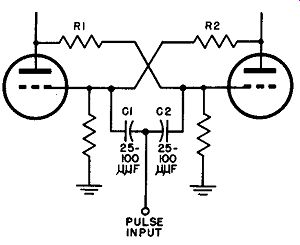
Fig. 6. How trigger pulses may be applied to both tubes at the same time,
through capacitors C1 and C2.
Pulse Output. In binary counting or two-to-one scaling systems (Par. 12 and Fig. 7) , it is desired that two input pulses produce one output pulse of essentially the same waveform as the input; each of these output pulses may then be used as the input to a succeeding scaler, which again reduces the counting rate by a factor of two.
Such a cascaded "binary counter" is very useful in counting neural impulses of high repetition rate, cosmic rays, radioactive particles, etc. when the impulses arrive too fast to be counted on a slow mechanical register. The production of such output pulses is quite easy. The normal square wave on the multivibrator plate is differentiated by an RC network having a time constant that is small compared to the time between pulses. "Peaking" takes place, and a series of positive and negative pulses result, as shown in Fig. 7.
This means that for every two positive input triggers there is one positive output pulse. If n scale-of-two circuits are used in cascade, a frequency division of 2" is obtained. For example, six such units provide a scale of 64, one output pulse being obtained for every 64 input pulses.
Plus and Minus Triggers. Negative triggers function as satisfactorily as positive ones. In the case of a negative trigger, the on tube current is decreased, and this initiates the action. As a matter of fact, positive and negative triggers may be present in any mixture--regular or random--and each pulse will trip the circuit regardless of polarity. Nor do the pulses have to be of the same amplitude, as long as the smallest of them have sufficient intensity to initiate the transition. When positive pulses are used, excessive amplitude must be avoided because a pulse that is too large has a tendency to charge the input capacitors, and (once the pulse has passed) there may be an effective negative pulse as the capacitor discharges. If the input pulse width is narrow, the positive and negative triggers follow each other so rapidly that they tend to cancel without activating the multivibrator at all; if the pulse width is great, both the true and the spurious trigger will start transitions, giving an incorrect count.
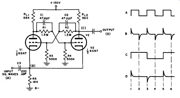
Fig. 7. Binary counter type of multivibrator, with trigger pulses applied
at the cathode.
Shunt Capacitance. Emphasis has been placed on the abrupt voltage changes that take place in a multivibrator; this is what makes high speed counting possible, since the resultant waveforms are steep sided and lend themselves to high repetition rates. A capacitor shunting such a voltage tends to prevent the abrupt change and, therefore, slows down the circuit reaction. The obvious conclusion is, therefore, that such capacitances must be held down to the lowest possible values. The input capacitors (Fig. 6) must be made very small so that the input time constant may be of the order of 15 microseconds. This in turn demands that the trigger pulse width be even smaller than this; otherwise, input differentiation may occur and cause erratic action as explained previously.
Improved performance is obtained if the input trigger is not square but has an exponentially sloping lagging edge; such a waveform reduces the tendency toward differentiated overshoot and stabilizes the tripping action. Since this is just the waveform obtained from a multivibrator through a short time-constant RC coupling net work, these circuits may then be used in cascade for scaling applications with no intervening pulse shaping networks.
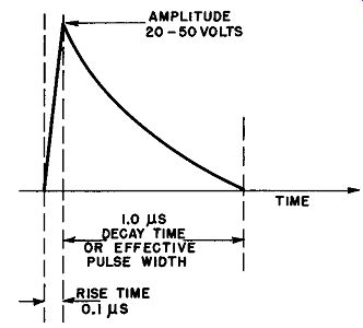
Fig. 8. Characteristics of pulse suitable for reliable triggering of multivibrator.
For the same reason that it is desirable to have a gradually sloping lagging edge, it is necessary for the trigger pulse to have a very rapid rise time at its leading edge. If the rise time were long, the short time-constant input circuit would attenuate the pulse to the point where it could not trip the circuit at all. Experience indicates that reliable triggering may be obtained by using an input pulse having these characteristics (Fig. 8) : Rise time: 0.1 microseconds Decay time: 1.0 microseconds, exponential Shape: peaked Amplitude: 20 to 50 volts Commutating Capacitors. For fast, reliable operation, the circuit of Fig. 5 and Fig. 6 requires one minor modification: the addition of capacitors across the coupling resistors, R1 and R2. Without these, a very fast input trigger of the order of 1 or 2 microseconds can come and go without activating the circuit. The reason for this is as follows: suppose that an ideal negative pulse shuts off V2 in zero time. The voltage at the plate of V2 rises to B+ value instantaneously, unless there is heavy capacitive loading; it may be safely assumed that the loading is light enough to allow this instantaneous action to occur. The voltage at the grid of V1, however, cannot follow this sudden change because of the fact that the input capacitance of the tube as an amplifier may be as high as 50 µ.µ.f and because the input trigger capacitor, C1 (Fig. 6), is also essentially in shunt with the grid circuit of V1. A total capacitance of approximately l 00 uuf combined with about 1 megohm of resistance (R2) yields a time constant of 100 microseconds, certainly too long to respond to a 1-microsecond trigger. This difficulty is overcome by shunting R1 and R2 by so called commutating capacitors of about 50 uuf apiece, as illustrated in Fig. 7. This balances out the effect of the shunt grid capacitances and permits the grid voltage to follow the plate voltage changes instantaneously.
12. Practical Binary Scale-of-two Counter
The circuit shown in Fig. 7 and variations of it are utilized in such equipment as time-division multiplex communications devices, locking tone keyers, and frequency shift keying units, in addition to being found in computers, radiation counters, and frequency measuring apparatus. It differs from the circuit just discussed in that the input triggers are introduced at the cathode rather that at a grid or plate, and is included here to show how this variant method of excitation operates.
Assume that V1 is full-on and V2 is cut off. A square wave (A) is now applied lo the input terminal and is differentiated by C3R5 to form pulses (B). First consider the case of a positive pulse.
The voltage drop already existing across R5 due to the cathode current of tube V1 is momentarily increased, the cathodes of both tubes being driven more positive. Tube V2, already cutoff (cathode positive and grid relatively negative) is not affected by this increase in the positive potential of its cathode. Tube V1, however, had its grid at a slightly higher positive potential than its cathode.
(The amount is limited by the grid current flowing through R3.) The positive pulse excitation applied across R5, effectively inserted into the grid circuit to make the grid relatively negative, is amplified in the conducting tube, V1. This reduces the plate current and produces a positive pulse at the plate of V1 that is then transferred through C1 and R1 to the grid of V2. If it is of sufficient magnitude, it starts the runaway action, with V2 becoming conductive and V1 reaching cutoff. The status is thus reversed.
Upon the arrival of the next negative pulse in the pulse train, both cathodes are driven more negative, tending to increase both plate currents. V2, already full-on, is affected very little, developing a very slight increase in its plate current, which results in a negative pulse at its plate; small as this may be. it is transferred to the grid of the cutoff tube, V1, and helps to hold VI cut off. Thus the negative pulse (if not too large) does not trigger a transition, and V2 remains conductive until the next positive pulse arrives.
See Fig. 7 (C) , points 1 through 3.
Since the circuit is symmetrical and the input excitation is applied to both cathodes, the foregoing discussion holds true for any initial tube condition (either V1 or V2 conductive). As the wave forms in Fig . 7 show, two input square wave cycles are required to produce one output cycle; similarly, if the output is differentiated by an RC network connected to the plate of V2, one output pulse is obtained for every two input pulses (D) . If it is preferred, excitation may be applied to the grids through capacitors as in Fig. 6. In this event, transitions are brought about by negative rather than positive pulses, but the same scale-of-two action is obtained.
13. The Bi-stable Multivibrator as a Regenerator
In reading the preceding paragraph, particularly that portion dealing with the ineffectiveness of negative pulses as triggers, it may have occurred to the reader 'that the cutoff tube, even though "held" at cutoff by the small pulse fed back from the conducting tube, tends to go into conduction when the cathode is driven negative. Whether it does or does not depends largely on the amplitude of the pulse. If it is assumed that the conducting tube circuit is such that the tube is really full-on (i.e., drawing near-maximum plate current) , a negative pulse applied to its cathode would produce an almost negligible holding pulse to the cutoff tube, since its plate current cannot rise significantly, even with excitation of the right sign.
On the other hand, if the amplitude of the pulse is two or three times greater than that required for reliable scale-of-two triggering, there will come a point at which a negative pulse applied to the cathodes will also cause a transition to take place by driving the cutoff tube into conduction to start the runaway process once again. Thus, the system acts not as a frequency divider but as a repeater or regenerator, putting out square-wave voltage or pulses at the same frequency as that of the input excitation. The comparative waveforms for this result are given in Fig. 9.
14. The Bi-stable Multivibrator as a Locking Circuit
In this application, the multivibrator functions in exactly the same manner as the regenerator, except that the pulses are delivered at a slower rate, so that the circuit may stay locked-in in either of its two stable states until the arrival of the next pulse. The arrangement provides the electronic equivalent of a pulse-energized electromagnetic relay locking in whichever position it is "kicked to."
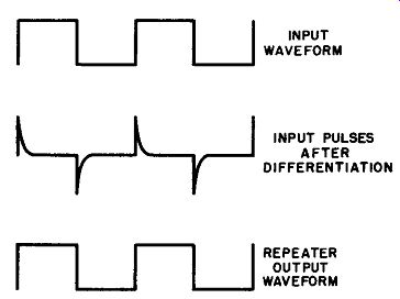
Fig. 9. Waveforms for re generator, or repeater, type of multivibrator.
As a rule alternate positive and negative pulses of voltage are applied to one grid instead of to the two cathodes in parallel, as in the case just discussed. The cathode is generally connected directly to ground instead of through a resistor, bias being obtained from a battery or other similar source.
15. Diode Trigger Feed
The basic methods of triggering a bi-stable multivibrator have been described in the preceding paragraphs. Mention also has been made of the fact that the multivibrator tube should not draw grid current while being tripped, and that the input circuit should not load down the grids. Flow of grid current may always be avoided, regardless of input pulse amplitude, by using negative triggers exclusively.
The grid loading problem and much of the trigger waveshape difficulty may be overcome by feeding the pulse to the multivibrator through diodes, as illustrated in Fig. 10. The diodes may be dual tubes, such as the 6H6, 6AL5, or germanium (or silicon) crystal rectifiers.
In the arrangement of Fig. 10, the input pulse must be negative, but positive pulses may also be used if the diodes are re versed. The diodes function as follows: assume that V1 is full-on and V2 is cut off. Under these conditions, the plate of diode V1 is negative with respect to its cathode, since the voltage on this tube is that which appears across R_L1. Hence V1 is not conducting. Diode V4 is in the non-conducting state too, because its plate voltage comes from the drop across R_L2, and (since V2 is cut off) there is zero voltage across this resistor; with no difference of potential between cathode and plate, V4 must also be quiescent. These conditions represent a stable condition until the arrival of a negative trigger pulse.
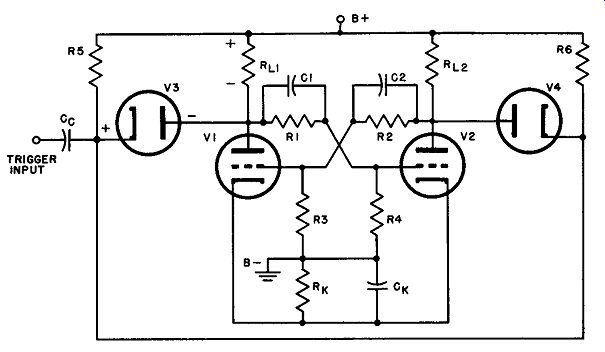
Fig. 10. Circuit employing diodes to minimize trigger-source loading.
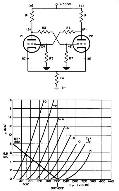
Fig. 11. Bi-stable multivibrator circuit and 6SN7 characteristic curves used
in simplified design procedure in text.
With neither diode conducting, the multivibrator is essentially disconnected from the trigger source and is thus loaded down only by the diode interelectrode capacitances, which are very small and may be ignored. A negative trigger pulse is now fed through the coupling capacitor, Cc. Unless it is very great in amplitude, it has no effect upon V3, because this tube's plate is so negative with respect to its cathode that only an unusually large input pulse could reverse these conditions. The instantaneous negative voltage on V4, however, causes this tube to conduct (the path is through R_L2 and R6) so that a relatively large negative trigger appears at the plate of V2. This is coupled to the grid of V1 through R2C2, starting the runaway cycle and resulting in a reversal of status, with V1 cut off and V2 conducting.
Much less attention need be paid to the trigger shape when diode coupling is used than in the simpler circuits. Although the input pulse must still have a very short rise time, the shape of the pulse and the characteristics of its trailing edge are comparatively unimportant. Even if the pulse has a positive overshoot, it cannot get through the diodes and cannot cause spurious triggering. The time constant of R5Cc and R6C" is not critical, although it should be short compared to the interval between pulses. At the instant of diode conduction, the time constant changes from R6Cc (assuming V4 is already cut oft) to the product of Cc and the joint resistance represented by R6 in parallel with the series combination of R_L2 and the internal diode resistance. If this is small compared with the pulse interval, there will be differentiation of the trigger, but this can do no harm since the diodes are impervious to positive overshoots. Capacitor C0 will charge, however, and must discharge before the next pulse arrives; otherwise, the pulse will not reach the diodes. This accounts for the need for making R6C0 (and R5C,,, of course) smaller than the pulse interval.
16. Simplified Design Procedure for Bi-Stable Multivibrator
A rigorous procedure for determining the circuit parameters of a specific bi-stable multivibrator is rather tedious and time consuming. For the average worker in electronics, the simplified sequence given below more than suffices, even though certain fundamental assumptions and compromises with rigidity must be made.
Given: A 6SN7 is to be set up as a bi-stable multivibrator and is to be used with a power supply that provides 300 volts (Fig. 11) . Assumptions:
a. With a power supply voltage of 300 volts available, we shall want the cathodes quite positive with respect to ground, so that we shall have plenty of "play" between these points to establish operating bias. Assume the cathode-to0 ground voltage desired to be about 100 volts.
b. Assume a reasonable value of load resistor R1. The triode sections of a 6SN7 have the same characteristics as the 6J5. A suit able load resistor might be about 25,000 ohms. This will later be tested and, should it prove too high or too low, the process may be repeated with a different assumed value.
c. During the quiescent condition, one triode will be cut off and the other will be full-on. To insure complete cutoff, the required bias voltage may be assumed to be about twice the actual cutoff bias value. For the full-on condition, the control grid will have to be zero or slightly positive for this triode section.
d. The individual values of R2 and R3 are considerably higher (10 to 20 times) than that of resistor R1, so that the voltage drop across R1 due only to voltage divider current is negligible.
Procedure:
a. The load resistor, R1, is chosen as 25,000 ohms (assumption b). A load line for this resistance is to be drawn in the 6SN7 plate characteristic curves. Since the cathodes are to be at 100 volts positive (assumption a), the load line is to be constructed for a plate cathode potential of 200 volts. This load line is shown in Fig. 11.
b. The conducting tube has a control grid voltage that is close to zero (assumption c). Find the plate current that flows in the conducting tube at this bias voltage from the intersection of the load line in the Eu = zero curve. This current is 5.5 ma. The figure also shows that at this plate current the voltage across the tube is 60 volts and the drop across R1 is 140 volts.
c. 5.5 ma must also flow through the cathode resistor, because only one tube is to conduct at a time when quiescent. To obtain a cathode potential of 100 volts, then, the cathode resistor must be:
R4 = 100
[...]
= 18,000 ohms
d. According to the average plate characteristics (Fig. 11) , the tube, with 200 volts plate-to-cathode potential, cuts off at -12 volts of bias. To insure against spurious triggering, assume the grid voltage needed is -25 volts (assumption c).
e. Assume V1 to be non-conducting at the moment. Its cathode potential is 100 volts positive and its grid potential is -25 volts with respect to cathode. Therefore, the voltage coupled from V2 (point F) is + 75 volts, and the voltage drop across R1 must be 75 volts. But the potential at point F is 160 volts with respect to ground (140-volt drop across R1 subtracted from supply voltage of 300 volts= 160 volts at point F). Thus there must be an IR drop of 85 volts from F to C and a 75-volt drop from C to ground. This determines the ratio of R2 to R3 as 85/75.
f. These resistors are to be high in value (assumption d). If R2 is arbitrarily selected as 500k ohms, R3 must be 440k ohms to agree with the ratio derived in ( e ).
g. These resistors, chosen to place the grid of the non conducting tube (point C) 75 volts above ground must now be tested to determine whether or not they conform with the second part of assumption c; i.e., that point G is at zero potential or slightly positive. With V1 non-conducting, and its grid at -25 volts with respect to cathode, its plate voltage with respect to ground (point B) will be very nearly 300 volts (assumption d) . Using resistors of 500k ohms and 440k ohms, point G would, if isolated, have a potential of + 135 volts with respect to ground, or 35 volts more positive than the cathode. When point G is connected to the grid of V2, grid current flows and prevents the grid from becoming more than a fraction of a volt more positive than the cathode. Thus the initial assumption is justified, and the resistor choices, including the selection of R1, are practicable.
17. QUIZ
(1) Draw the circuit of the bi-stable multivibrator, utilizing a bias supply. Assign typical values to the components and explain the circuit operation.
(2) What role does the bias voltage play in a bi-stable multivibrator?
(3) What is a "trigger circuit"? Explain "trigger action" in a bi-stable multivibrator.
(4) Define transition; refer to Fig. 3 and explain why this effect prevents a "part-on, part-on" condition.
(5) How may the circuit of question 1 be adapted for self-biased operation? Draw and explain the resultant changes in circuit operation.
(6) Describe the modifications necessary when a succession of triggers are applied simultaneously to both grids in the modified circuit of question 5.
(7) What type of coupling is normally utilized for square wave output? Why are other types of coupling normally not applied?
(8) Explain the operation of plus and minus triggers in binary counters or two-to-one scaling systems. Draw the circuit of a practical binary scale-of-two counter.
(9) Explain the function of shunt capacitance and commutating capacitors in multivibrator operation.
(10) Draw comparative waveforms illustrating the action of the bi-stable multivibrator as a regenerator.