AMAZON multi-meters discounts AMAZON oscilloscope discounts
18. Conversion of Bi-Stable to Mono-Stable Multivibrator
Many multiplex telegraph transmitters and radar systems utilize the mono-stable form of multivibrator for timing and "delay" purposes. The mono-stable type (Par. 2) is distinguished from the bi-stable variety by its self-restoring action. In the bi-stable multi vibrator, a correct trigger produces a stable transition from one tube to the other; the mono-stable multivibrator may go through the same transition, but returns to its original condition spontaneously. This action is often called "flip-flop" in contrast with the bi-stable behavior which is referred to as a "flop-over." If the resistive coupling from one of the plates to the opposite grid in the bi-stable multivibrator is changed to capacitive coupling, a mono-stable system results. In the basic circuit, the corresponding grid resistor is returned to a positive potential, rather than to ground or to a bias source (Fig. 12, point A).
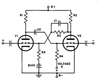
Fig. 12. Basic monostable multivibrator circuit.
19. Circuit Operation
In the quiescent condition, V2 is full-on. Its control grid voltage is zero or very slightly positive with respect to the cathode, the circuit values being so chosen as to establish V1 below cutoff. The circuit will trigger if a positive pulse is applied to the grid of V1 (or the plate of V2), or if a negative pulse is applied to the grid of V2 (or the plate of V1). In this circuit, the trigger pulse is applied to only one tube at a time, not to both tubes simultaneously as in the bi-stable type.
Suppose that an isolated negative pulse is injected into the grid of V2. The plate current of V2 decreases and a positive pulse appears at the plate of V2, and is transferred through C1 to the grid of V1, causing the plate current of V1 to rise. The negative pulse at the plate of V1, which results from this rise of plate current, is immediately passed on to the grid of V2 through coupling capacitor C2, reinforcing the original trigger. This starts the familiar runaway action, with the grid voltage of V2 rapidly forced negative to a point beyond cutoff. At the same instant, V1 reaches the full-on condition, since the transfer of voltages just described brings the grid of V1 into the zero or slightly positive region. However, this is only a quasi-stable state. After a fixed time interval has elapsed, the circuit, without the need for an additional trigger, reverts to the original condition, in which V2 is full-on and V1 is cut off.
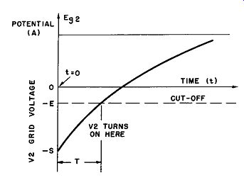
Fig. 13. Waveforms of grid voltage of V2, showing related circuit actions.
20. Explanation of Reversion Action
A thorough understanding of the reasons for the waveforms obtained from a mono-stable multivibrator requires a careful analysis of the voltage changes that occur in the circuit with the super imposition of the trigger pulse. (Refer to Fig. 13.) Let t = 0 represent the instant when the trigger pulse is injected, t = 0- an instant before pulse injection, and t = o+ the time when the "flip" is completed; i.e., when V 1 has gone from cutoff to full-on. At t = 0-, the grid potential of V2 is zero or very close to it as a result of the grid current flow through R4 (Fig. 12). At t = o+, the voltage on the grid of V2 falls to the point labeled -S on the axis of Fig. 13. This point is the negative swing of the plate potential of V1 as this tube goes from cutoff to full-on (as its plate voltage drops from a value virtually equal to B+ to its lowermost limit at the full-on condition) . As a result of this swing after the trigger has acted, capacitor C2 becomes charged, but once the quasi-stable state is attained, it begins to discharge through R4; since R4 is much larger than R1, the discharge time constant is approximately equal to R4C2 with R1 being ignored.
The equation of the discharge curve is: Egi = A - (A + S) l -t!R4C2
This equation is obtained from the consideration that at the be ginning of the discharge process Eui = -S and at t = infinity, E02 = A.
If the magnitude of the grid cutoff voltage of V2 is assumed to be -E as shown on the curve, this tube will start to draw current when Eu2 = -E. At the same instant, the plate voltage of V2 begins to drop, providing the pulse that pulls the grid voltage of V1 along with it. This is the beginning of the restoring action that returns the system to its initial stable state.
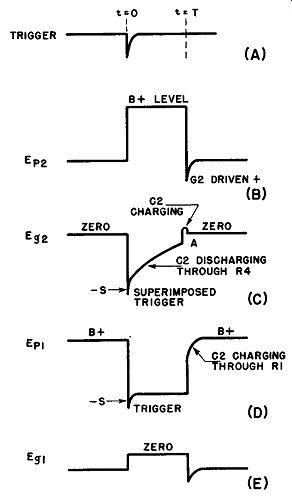
Fig. 14. Waveforms in monostable multivibrator.
The foregoing analysis assists in explaining the waveforms shown in Fig. 14. Consider first the region near t = 0. EP, rises very rapidly toward B+ (diagram B) with a time constant equal to the product of R2 and the capacitance at the plate of V2, which is always quite small. This results in a steeply rising leading edge to the B+ level. Eu, starts at -S and increases toward voltage A
with a time constant of R4C2, as already explained; the trigger is, however, superimposed at the start of the change (diagram C). Ep1 (diagram D) starts at B+ and drops almost instantaneously to the lower limit of its swing -S, but again the trigger is super imposed on the waveform, having been transmitted through C2 from the grid of V2 to the plate of V1. Eu 1 rises quickly from cutoff to zero, or it may overshoot slightly into the positive region ( diagram E) . Now consider the conditions that obtain at the end of time T, the end of the quasi-stable state. As EP1 rises toward B+ (diagram D), this change of voltage appears at the grid of V2, driving it positive, and the resulting grid current charges C2 until Eui returns to zero as shown in diagram (C) . This overshoot in Eu2 causes a very large negative overshoot in Ep2 (diagrams C and B), which drops very quickly as a consequence of the heavy current drawn by V2.
Ep1, however, rises comparatively slowly (diagram D), because the current that charges C2 must pass through R1. In addition, the overshoot in EP2 reflects itself in a similar overshoot in Eu1 (diagram E). Since the mono-stable multivibrator generates a rectangle for a peaked trigger, it can be used to gate other circuits; furthermore, since the output can be differentiated to give an output pulse that is delayed a predetermined time T after the incidence of the trigger pulse, it may be utilized for accurately controlled delay purposes.
21. Self-biased Mono-Stable Multivibrator
The circuit of Fig. 12 has the disadvantage that a source of negative voltage is required. A mono-stable multivibrator in which self-biasing is accomplished is illustrated in Fig. 15. In addition to this change, it should be observed that coupling resistor R3 and its shunt capacitor (Fig. 12) are both missing; feedback takes place through common cathode resistor R5, making other feedback components unnecessary. Another advantage of this arrangement is that the plate of V2 is not connected to anything except R2, i.e., to no significant capacitance except that of the output capacitor (and the tube's plate-to-ground capacitance) , which may be very small. Thus a very fast waveform is obtainable at this Point.
Its operation may be described as follows: in the quiescent state, V1 is cut off, due to the high bias applied to its cathode. This bias is the drop across R5, and results from the high plate current flowing through V2, this tube being in the conducting state, since its grid is effectively at cathode potential through R4.
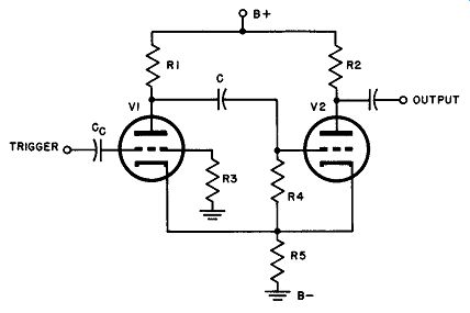
Fig. 15. Self-biased monostable multivibrator.
Now a positive trigger of sufficient amplitude is applied to the grid of V1 through coupling capacitor Cc, causing V1 to rise out of cutoff and begin to conduct. The flow of the plate current produces a negative pulse at the plate of V1. This pulse is transferred to the grid of V2 through capacitor C. The plate current of V2 then decreases, the voltage drop across R5 drops, permitting V1 to draw still more plate current, increasing the negative pulse at its plate, etc. The transition to the state in which V1 is full-on and V2 is cut off proceeds as before and the circuit remains in the quasi stable condition until C discharges sufficiently to allow the grid of V2 to rise from the voltage beyond cutoff to the point where conduction may once more begin. As V2 begins to pass plate current, the voltage drop across R5 again starts to increase, reducing the plate current of V1, which in turn transmits a positive pulse to the grid of V2 to bring the circuit back to its original stable state.
In analyzing the circuit operation of this arrangement, the question of the relative conductivities of the tubes when either is full-on often arises. With no trigger applied, the grid of V2 is at cathode potential so that its bias is zero; when V1 is full-on, however, its grid is always negative with respect to its cathode, since the former is returned to ground; hence there is always some negative bias. Thus in the stable state the current through R5 is considerably higher than in the quasi-stable condition, and it is this variation of cathode current that accounts for the feedback.
22. Self-biased Mono-stable Multivibrator with Positive Grid Return
For very precise timing applications, the circuit shown in Fig. 16 is preferred over that of Fig.. 15. The significant difference between the two arrangements is that R4 in the latter case is returned to B+ rather than to the cathode; also, the grid of V1 is at a fixed voltage, E, controllable by the setting of R3.
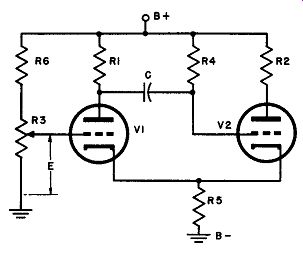
Fig. 16. Modification of self biased monostable multivibrator, for accurate
timing.
Let us examine the sequence of operational events first, then determine the advantage that the positive grid return has over the ground grid return. In the quiescent state, V2 is full-on with its grid-cathode voltage at zero potential or slightly positive. Voltage E is made less positive than the cathode potential of V 1 by an amount equal to at least the cutoff voltage of the tube, thus V1 is non conductive. A negative trigger injected into the grid of V2 causes the plate current of the tube to decrease, with a consequent reduction of the drop across R5. If the change is sufficient, V1 will be gin to conduct and start the runaway action. At the end of the transition period, which is virtually instantaneous, the grid of V2 has been driven far below its cathode, but its potential immediately begins to rise exponentially toward B+ with a time constant equal to R4C. (R1 is neglected since, as usual, its resistance is very much lower than R4.) As soon as the potential on the grid of V2 rises above cutoff, the circuit flips back to the stable state.
The more accurate timing action of this circuit as compared to the one using cathode return is explained as follows: referring to the instant when the circuit has reached the quasi-stable state with V2 cut off and V1 full-on, capacitor C in both cases begins to discharge toward the point where V2 will come out of cutoff and start to conduct. To cut V2 off, in the multivibrator of Fig. 16, C must charge to a relatively high voltage, because the grid of the tube is connected to the high positive voltage of the supply; thus, to allow conduction to occur once again in V2, only a comparatively small discharge need occur, taking place along the very linear portion of the curve (Fig. 17 A) .
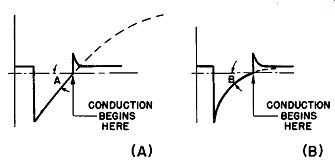
Fig. 17. Comparison between timing action in circuit of Fig. 16(A) and in circuit
of Fig. 15(8).
Angle A indicates that the approach to the cutoff voltage is very rapid, so that slight changes in circuit conditions and voltages have negligible effect upon the time required for C to discharge to the conduction point. Contrast this with the behavior of C in the circuit of Fig. 15, illustrated at (B) of Fig. 17. Here C takes on a much smaller total charge at the end of the transition period, and hence must discharge almost completely before the restoring action commences. Hence its discharge occurs over a much greater length of the curve, approaching the cutoff point at a relatively small angle (angle B indicating slow approach) . In this situation, the same small variations in tube or circuit conditions are apt to produce a serious change in the timing.
In addition to its timing accuracy, the circuit of Fig. 16 has another marked advantage over other types. The time required for the completion of one cycle is a linear function of voltage E, hence this arrangement makes an excellent delay gate, whose width is easily and linearly controlled by the setting of R3.
23. Frequency Division or "Counting Down"
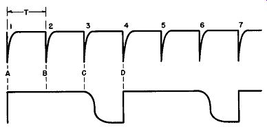
Fig. 18. Waveforms illustrating frequency division (counting down) in a mono
stable multivibrator.
The mono-stable multivibrator is well-suited to frequency division applications, particularly when odd divisions, difficult to obtain with the bi-stable type, are required. Consider a regular train of pulses spaced a time, T, apart as in Fig. 18; assume that the output pulse width of the mono-stable multivibrator has been adjusted to occupy a time somewhere between 2T and 3T. Refer ring to the positive grid return setup of Fig. 16, the first negative pulse in the train, applied to the grid of V2, almost instantaneously triggers the transition, so that a positive voltage appears at the plate of V2 (point A, Fig. 18) . V2 remains cut off through the interval while pulses 2 and 3 appear and, since these are negative pulses like the first, they cannot affect the circuit, because V2 is already cut off. After pulse 3 has passed, the charge on C decays sufficiently to permit the circuit to return to the true stable state quickly (between c and d) so that it is in readiness for the arrival of pulse 4, which causes the process to repeat.
When the time constant, R4C, and the magnitude of E are properly selected to yield this effect, the multivibrator will produce output pulses, after differentiation, which correspond to input pulses 1, 4, 7, 10, 13, etc. This, then, is a 3:1 frequency division, as used in DuMont Image Orthicon Camera Chain TA-124-E, de scribed in the next paragraph. The stability of this type of frequency divider depends upon the constancy of the multivibrator period and, if it is desired to count down, say, 100:1 the width would have to lie between 99T and 100T. If, for any reason, the width should wander outside these limits, there would be a false count, perhaps 99: 1 or 101: 1 stable divisions as high as 25:1 can be obtained under laboratory conditions; in commercial equipment the division is usually limited to 7: 1 or less for dependability.
24. A Commercial Three-to-one Mono-stable Multivibrator
The 3:1 count multivibrator to be described is used in an Image Orthicon Camera Chain (DuMont TA-124-E) for counting down trigger pulses which originate in a 31.5- khz controlled blocking oscillator. This frequency is successively divided by a cascaded ...
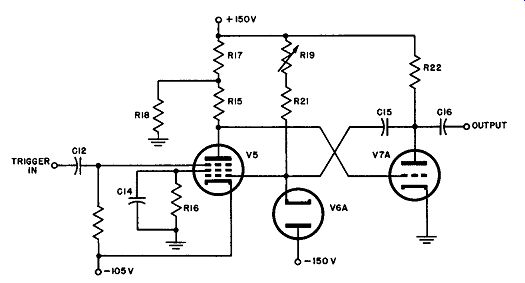
Fig. 19. Circuit of 3: 1 count-down multi-vibrator. (After DuMont)
... group of four mono-stable multivibrators by counts of 3, 5, 7, and 5, the output frequency of the group being 60 cycles, the television field-rate:
31.5 /3 10.5 khz
10.5/5 2.1 khz
2.1/7 .3 khz = 300 hz
300/5 60 hz
The circuit of the 3: 1 count multivibrator is given in Fig. 19.
V5 is conducting because a positive potential of nearly 150 volts is applied to its control grid through RI 9 and R21, while its cathode is at a potential of -105 volts. The grid current flowing through R21 and R19 makes this grid, therefore, zero or fractionally positive. Assuming little voltage drop in the tube, this heavy conduction forces the plate of V5 (hence the grid of V7 A) to assume a voltage close to that of the cathode of V5. For this reason, V7 A must be at cutoff or beyond, its control grid close to -105 volts, with cathode at ground potential. This is the stable state of the system.
The application of a negative pulse to the suppressor of V5 produces a sharp drop in plate current, a positive pulse at its plate and therefore at the grid of V7 A, and a rise of V7 A into conduction.
Thus a negative pulse appears at the plate of this tube and is transferred to the control grid of V 5 through C15, dropping the plate current of V5 still further. The action ceases temporarily when V5 is at cutoff and V7A is full-on, with capacitor C15 charged to the new voltage conditions. As the charge leaks off, a point is reached at which V5 can again begin to conduct; this, of course starts the process in which the system returns to its stable state.
The output square wave is differentiated through C16 and the grid circuit of the next stage, providing a strong negative trigger pulse of the desired waveform for activating the succeeding counters.
Note the connection of diode V6A. In the quiescent state, the cathode of this tube is virtually at zero potential and its plate sees -150 volts of applied potential from the power supply; thus 150 volts of inverse potential appears between its electrodes. The reader may recognize this as a simple diode damping system whose function is to limit the pulse voltage applied to the control grid of V5 regardless of variations that may appear at the plate of V7 A. Should the fed-back pulse amplitude become too great, V6A conducts and instantaneously reduces its size to its former "clamped" value.
The time constant of the system is chosen by the proper adjustment of R19; since this resistor governs the time required for discharge of CJ5, this is the interval in which the circuit remains in the quasi-stable state; it controls the frequency division ratio, in this case 3:1.
25. QUIZ
(1) How is a bi-stable multivibrator changed to a mono-stable multi-vibrator?
(2) Draw the circuit of a mono-stable multivibrator.
(3) Detail and explain the circuit operation of a mono-stable multivibrator.
(4) Explain "reversion action" in a mono-stable. multivibrator.
(5) Diagram the waveforms obtainable from a mono-stable multivibrator.
(6) How may a mono-stable multivibrator he used to gate other circuits? For accurately controlled delay purposes?
(7) How does the circuit of Fig. 15 act as a multivibrator?
(8) Re-draw Fig. 15 so as to convert it to a self-biased mono-stable multi vibrator with positive grid return.
(9) Show the application of a mono-stable multivibrator to frequency division or counting down.
(10) Explain the operation, advantages, and applications of the circuit drawn in answer to question 8.