AMAZON multi-meters discounts AMAZON oscilloscope discounts
26. Action of the Fundamental Circuit
The a-stable multivibrator differs from the bi-stable type in that the plate of each tube is capacitively coupled to the grid of the other rather than being coupled through resistors. Compare Fig. 20 with Fig. 5. This difference converts the bi-stable multivibrator to a form in which the transition from one stable state to the other occurs automatically and periodically, with the result that free running square-wave oscillations are obtained.
The circuit may be set up symmetrically with R_L1 = R_L2, C1 = C2, R_g1 = R_g2 ,, and the two tubes having identical parameters. One might suppose that such symmetry would lead to a stable condition in which both tubes are full-on or part-on, de pending upon the sizes of the grid resistors and the amount of contact-potential bias developed. This supposition is indeed a possibility until one considers that even if the arrangement is absolutely symmetrical, instantaneous conduction in both triodes can not be identical at successive intervals due to inherent tube "noise," unequally distributed emission along the length of the cathode, and other random effects that must inevitably contribute to an instantaneous difference between the two plate currents. As soon as this difference exists, circuit action commences. In actuality, oscillations start as soon as the tubes are heated and the plate potential is applied.
Let is start by assuming both plate currents to be equal and assuming also that a burst of electrons from the cathode of V1 increases the plate current of this tube slightly; instantly, the plate potential drops and a negative pulse appears at the grid of V2.
The resulting positive pulse at the plate of V2 is then fed back to the grid of V1 through C1, further inc. Teasing its plate current, thus starting the transition, which terminates when V1 is full-on and V2 is cut off. As in the other multivibrators discussed in previous sections, the transition occurs almost instantaneously.
An analysis of the grid and plate waveforms is best started from this point and, for clarity, certain reasonable figures may be assumed for the circuit voltages and component values. These are shown in Fig. 20.
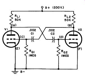
Fig. 20. Basic a-stable multi vibrator circuit.
With V2 non-conducting, the potential at point B must be equal to the supply voltage, since there is no drop in Ru, (i.e., Ep, = approximately 200 volts). At the same time, a full-on condition in tube V1 means that its grid is at or near zero potential with respect to ground, so that C1 must be charged to about 200 volts negative on the V1 grid side. When the grid of V1 is near zero, however, the potential at point A is about 40 volts. This figure is obtained by drawing the 50k ohm load line into the plate characteristics of 1/2 6SN7 or a 6J5, typical multivibrator tubes. Consideration must also be given to the voltage at the grid of V2 at this instant: at cutoff, a very high negative potential must appear on the grid; as we have done before, we might assume a voltage of at least twice cutoff, but, as we shall see, it is actually much greater than this. As a matter of fact, it is approximately equal to the swing of the V2 plate voltage during transition. (200 - 40 = 160 volts.)
Ep2 200 volts Eg2
- l 60 volts
Ep1 40 volts
Eg1 zero volts
Therefore:
Charge on C1 = 200 volts
Charge on C2 = 65 volts
Consider now what must be happening in the grid circuit of V2 if there is a -160-volt difference between the grid and cathode: a current must be flowing through grid resistor Rg2 under the pressure of this difference of potential. Obviously, this current must be flowing out of C2, because grid current cannot flow when the grid is so negative with respect to cathode; thus the voltage across C2 must be changing. This capacitor must be "moving" up along an exponential discharge curve, which would terminate when Rg2 stops taking current or, in other words, when point D reaches ground potential (if other events did not prevent it) . Something does happen, however, that changes the smooth discharge of C2: at the same time point D arrives at the -12-volt level, V2 begins to conduct, sending a negative pulse to point C, producing a positive pulse at A and, therefore, a positive pulse at D. Thus the potential at D is suddenly lifted above the zero axis (Fig. 21), but drops quickly to approximately zero as the V2 grid draws current and brings the potential at D to ground level.
All that remains now is to show that, at the instant when V2 begins to conduct, EP1 (point A, Fig. 20) , jumps from its conducting plate voltage of 40 volts to its cutoff plate voltage of 200 volts, completing the second transition. As V2 starts to conduct, point B begins to become less positive, carrying C with it. The time required for V2 to go from the condition where conduction just starts to the tip of the overshoot (Fig. 21) is virtually zero, hence C goes to the -160 volt point just as quickly, with VI cutting off almost instantaneously. The process now repeats, this time with C1 discharging along an exponential curve until conduction in V1 again commences. The grid voltage waveforms for V1 are, therefore, exact reproductions of those for V2, but are displaced by 1/2 cycle along the time axis.
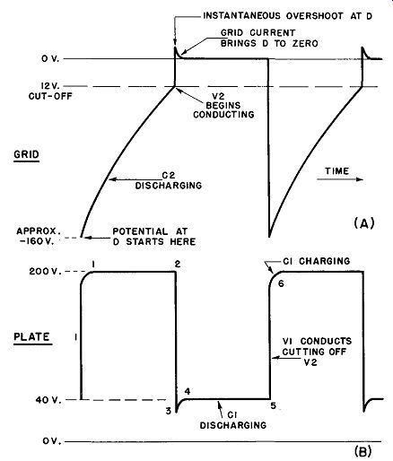
Fig. 21. V2 waveforms in a-stable multivibrator.
The output waveforms at the plate of V2 are shown in Fig. 21 (B). They begin at the point where the grid of V2 is well below cutoff (-160 volts), no current is flowing in the plate-cathode circuit, and the plate potential is equal to that of the supply (200 volts). The voltage at B remains at this level until the instant when V2 begins to conduct; now the almost instantaneous change takes place in which the grid of V2 soars above the zero line (instantaneous overshoot), taking the plate voltage down into an over shoot below the 40-volt line, as shown from 2 to 3 in Fig. 21 (B). The plate potential of V2 is quickly established at 40 volts as grid current brings the V2 grid to zero (3 to 4), remains at 40 volts as C1 discharges (4 to 5), and then returns to the 200-volt level when V1 begins to conduct and cuts off V2 (0.5 to 6).
The rounded corners at 1 and 6 are due to the charge time of C1. Since this period is extremely short, such defects in the square waveform are not noticeable in practice. Of course, the output waveform at the plate of V1 is the same as that for V2, again being displaced along the time axis by 1/2 cycle.
27. The Frequency of the Multivibrator
Formulas for computing the frequency of an a-stable multi vibrator are available, but these are complex, difficult to apply, and outside the scope of this book. A surprisingly accurate measure of the frequency of a multivibrator may be obtained, however, by applying the foregoing analysis.
Three factors are of importance in frequency determinations:
a. The RC time constant of each capacitor-resistor combination in the grid circuits of the tubes. Assume these to be sym metrical.
b. The actual cutoff voltage of the tubes.
c. The plate voltage swing between the conducting and the non-conducting state.
Again, a numerical example helps to explain the procedure.
We shall use the circuit and values of Fig. 20. When a tube goes from a non-conducting to a conducting state, its plate voltage drops from 200 volts to 40 volts. This forces the grid of the other tube to jump from about zero volts to a level of -160 volts. This tube remains non-conductive until the capacitor discharges from -160 volts to the cutoff level, -12 volts in our example. While the total possible discharge range is from -160 volts to zero volts, i.e., 160 volts of change, the actual range is only 148 volts (-160 to -12) . The real change is then:
!!~ = .925 = 92.5 percent of the possible change
The time required for a capacitor to discharge 92.5 percent of its voltage may be found in the universal time constant charts and is virtually equal to 2.6 time constants.
The time constant of either RC combination in the example of Fig. 20 is (R = 1 megohm C = .002 11 ,t): TC = 1 X .002 seconds 2.6 TC periods = .002 X 2.6 .0052 seconds
The time of .0052 seconds, then, specifies the interval during which either tube is cut off while the other is conducting, so that the time required to complete a full cycle is 2 X .0052 = .0104 seconds. The frequency (reciprocal of period) is, therefore, lj.0104 = 96.1 cycles per second.
28. Synchronization of the A-Stable Multivibrator
The dependence of the a-stable multivibrator period on a number of circuit and voltage conditions acting together leads to poor frequency stability, a condition which is advantageous when it is desired to synchronize the oscillator with some external signal source. A crystal oscillator, in contrast, is so stable that it is difficult if not impossible to make it synchronize with any frequency removed from its natural one. Thus the instability of the multi vibrator, a characteristic having an unpleasant implication, is the very thing that makes it so useful in most of its applications.
In modern practice, multivibrators are commonly synchronized by peaked waveforms, although other shapes, such as square or sinusoidal waves, may be employed if the conditions warrant. In any case, either a negative or positive pulse of sufficiently great amplitude may be used if correctly injected. Figure 22 illustrates the importance of pulse amplitude (positive pulse) in triggering a multivibrator before the end of its natural period so that it will synchronize at a frequency somewhat higher than its free-running repetition rate. In (A) , the pulse, at the time it appears, is too small to pull the tube out of cutoff, so that it comes and goes with out affecting the multivibrator frequency in any way. The natural half-period, as determined by the factors discussed in Par. 27, is shown here as t. When the pulse amplitude is greater (Fig. 22 B) , even though it appears at the same time as before with relation to the multivibrator cycle, switching does take place at point 1 rather than at point 2 when there are no sync pulses. Note that the half period is now substantially shorter (ti), which means that the multivibrator frequency is higher. The action is repetitive, of course, and synchronization holds cycle after cycle; under these conditions, the multivibrator is said to be "locked in." A positive trigger injected into a conducting tube cannot alter the frequency of the multivibrator, because the tube is already conducting. The pulse rides the top of the waveform (Fig. 22C) , with out influencing the multivibrator one way or the other. Negative synchronizing pulses are often present in timing equipment, and may be utilized to lock-in a multivibrator by injecting them into the grid circuit of the conducting tube. The action is an indirect one in this situation; the negative pulse does not cause the con ducting tube to revert suddenly to the cutoff state; rather it is amplified and inverted in phase by the conducting tube and is then applied as a positive pulse to the grid of the tube in the cutoff state. Hence the action is similar to that depicted in Fig. 22 at the instant of switching.
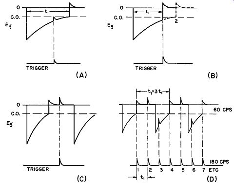
Fig. 22. Grid waveforms in a-stable multivibrator, showing trigger pulses.
(A) trigger too weak, (B) trigger controlling properly, (C) late trigger due
to natural multivibrator frequency higher than trigger frequency, (D) sync
at sub-multiple of trigger frequency.
In general, the natural period of the multivibrator must be greater than the interval between synchronizing pulses (Fig. 22B) if locking-in is to be realized; otherwise, the pulses arrive at the grid of the tube after it has gone into conduction, and cannot affect the frequency. Thus the sync pulse repetition rate must be of higher frequency than that of the multivibrator for successful synchronization. In some applications, the aim is to synchronize the multivibrator at some sub-multiple of the sync frequency; for example, the synchronization of a 60-hz multivibrator by pulses having a repetition rate of 180 hz. This is illustrated in Fig. 22 (D). The multivibrator is tripped on pulses 1, 4, 7, 10, 13, etc., the relationship between periods being 3:1 as shown in the diagram.
Synchronizing pulses are commonly injected into the multi vibrator system by means of coupling capacitors to the grid of one of the tubes or through a transformer having a low impedance secondary as shown in Fig. 23.
29. Cathode-Coupled A-stable Multivibrator
The circuit of Fig. 24 should be compared with that of Fig. 15, the self-biased mono-stable multivibrator. It will be noted immediately that the only difference between these two arrangements is that in the mono-stable circuit R4 is returned to cathode, while in the a-stable circuit this resistor is returned to ground. In the ...
Fig. 23. Transformer coupling of trigger to a-stable multivibrator.
... last few sentences in Par. 21, it was pointed out that the cathode return of R4 to V2 is capable of placing this tube in the stable state, because the grid bias is zero under these conditions, resulting in a heavy current through R5, the common cathode resistor. The large voltage drop across R5 provides a sufficiently high bias for V1 to keep it cut off; hence the circuit is stable. In the case of the ground-return grid resistor (R1 of V1 in Fig. 15), the current through R5 is not nearly as great, and the voltage drop across it is too small to keep V2 cut off after (C) discharges; therefore, this results in the quasi-stable state.
It should be evident from this that should both grid resistors be returned to ground as in Fig. 24 the circuit would have no stable state at all. In short, with either tube conducting the quasi-stable condition would obtain and, of course, must result in free-running oscillations.
The sequence of voltage transfers that result in one cycle of free-running oscillation is outlined below:
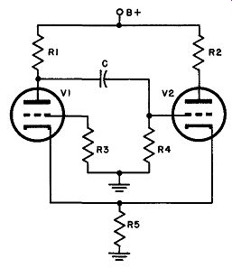
Fig. 24. Circuit of a-stable cathode-coupled multivibrator.
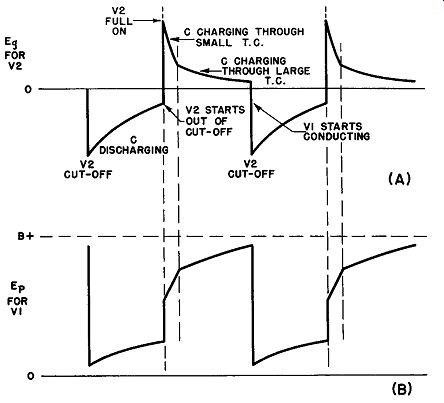
Fig. 25. Waveforms in cathode-coupled a-stable multivibrator.
a. With the application of power, plate current starts to flow in both tubes. Its size is limited by the bias applied as a voltage drop across R5.
b. Assume that the plate current of V1 is slightly greater than that of V2. This produces a negative pulse at its plate that is transferred instantaneously through (C) to the grid of V2, starting the transition which terminates with V1 full-on and V2 cut off.
c. When C discharges sufficiently, V2 rises out of cutoff, draws plate current, and increases the drop across R5, thus raising the bias on V1.
d. The plate current of V1 drops slightly, generating a positive pulse at its plate, which is instantaneously coupled to the grid of V2, increasing its plate current still further. Thus the transition to the state in which V2 is full-on and V1 is cut off takes place. V1 is held non-conducting by the large voltage drop across R5.
e. At the instant when the grid of V2 is driven positive by the pulse from the plate of V 1, grid current begins to flow in V2, and C begins to charge through two separate paths:
1. R5, cathode-to-grid resistance of V2, and R1
2. R4 and R1
The short time constant of these parallel paths permits C to charge quickly until the grid reaches cathode potential. Now grid current ceases, but the capacitor continues to charge through path (b) at a slower rate than before, because the time constant of this path alone is higher. When the voltage across R5 drops to the cutoff voltage of V1, this tube instantly starts to conduct, renders V2 non conducting by passing a negative pulse from its plates through C to the grid of V2, and the cycle is complete, with V1 full-on and V2 cut off.
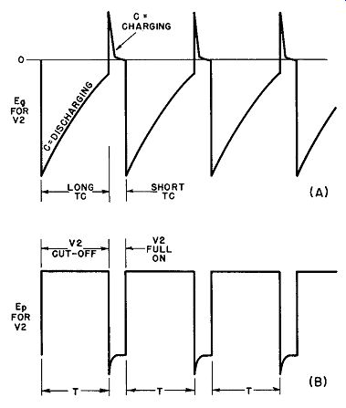
Fig. 26. Asymmetrical waveforms in cathode-coupled a-stable multivibrator
in which V2 grid draws current over most of cycle.
Figure 25 (A) illustrates the voltage variations at the grid of V2 and shows the change in waveform that occurs when C transfers from the low to the high TC charge path. The effect this has upon the voltage at the plate of V1 is pictured in Fig. 25 (B). Since the output square-wave from a cathode-coupled multivibrator is almost always taken from the plate circuit of V2 (in which square waves like those in Fig. 21 (B) are produced) the distorted voltages at the V1 plate are of no significance.
The cutoff interval for V2 is proportional to the time constant on discharge for capacitor C, while V1 remains cut off for a period that is a function of the charge time constant of the same capacitor.
The latter, as the foregoing discussion points out, may be subdivided into two distinct TC periods depending upon the presence or absence of grid current in V2. It is, therefore, quite easy to make the charge time constant much shorter than that of discharge by proportioning the circuit constants in such a way as to have V2 draw grid current for most of the half-cycle. When this is done, the output of the multivibrator becomes asymmetrical, as diagrammed in Fig. 26. The property of asymmetry 1s often useful in specialized radar and television applications.
30. QUIZ
(1) Differentiate between the a-stable multivibrator and the bi-stable type.
(2) Draw a circuit representing an a-stable multivibrator.
(3) Explain in detail the circuit operation of the a-stable multivibrator.
(4) Enumerate three factors of importance in the frequency determination of the a-stable multivibrator.
(5) Explain how an a-stable multivibrator may be synchronized with external signal sources.
(6) What is meant by "locked in" when the term is applied to a multi vibrator?
(7) What changes are necessary in Fig. 15 to convert the circuit to a cathode-coupled a-stable multivibrator?
(8) Explain the operation of the cathode coupled a-stable multivibrator.
(9) What type of waveform is most commonly employed to synchronize the a-stable multivibrator?
(10) Recapitulate briefly the differences between the fundamental classes of multivibrators reviewed to this point.