AMAZON multi-meters discounts AMAZON oscilloscope discounts
FIXED CAPACITORS
PAPER CAPACITORS
Basic construction. The simplest and most widely used form of paper capacitor consists of two strips of metal foil rolled up with strips of paper which have been impregnated with an insulating material. Impregnating materials commonly include various types of oils, waxes, and plastics. The type used determines the voltage, temperature, and insulation resistance characteristics of the capacitor. When the capacitor is to be used at high working voltages, several layers of insulating paper are used. Details of the most common construction are shown in Fig. 4-1 (A). After the foil and paper strips are rolled up, the protruding ends of the foil are crimped over so that the individual layers o( each strip are in electrical contact with each other. A lead is attached to each end, and an outer cover of insulating material is added. The cover is marked with the capacitance and working voltage as shown in Fig. 4-1 (B), and a black ring is usually printed around one end to mark the terminal which is connected to the outermost layer of foil. In low-cost capacitors the outer covering consists of heavy paper saturated with wax. In more expensive types the outer layer consists of a hard plastic material, which enables the capacitor to be used at higher temperatures without danger o( melting. In paper capacitors the total capacitance is predetermined by the thickness and dielectric constant of the paper and the total area of the foil plates.
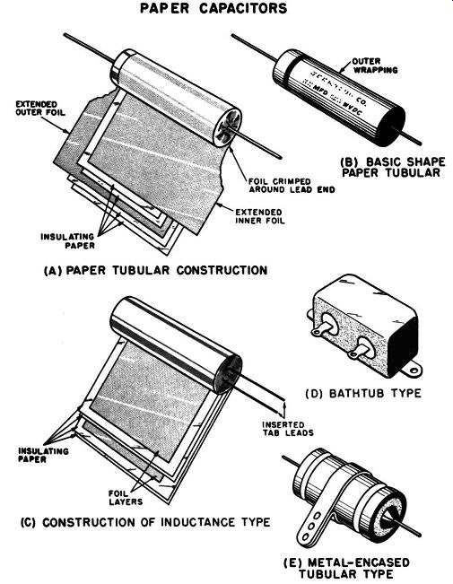
Fig. 4-1. Paper capacitor. (A) Basic: construction. (b) Markings. (C) Construction
of inductive type. (D) Bathtub type. (E) Metal-encased tubular. PAPER CAPACITORS
(A) PAPER TUBULAR CONSTRUCTION (C) CONSTRUCTION OF INDUCTANCE TYPE (D) BATHTUB
TYPE (E) METAL-ENCASED
TUBULAR TYPE
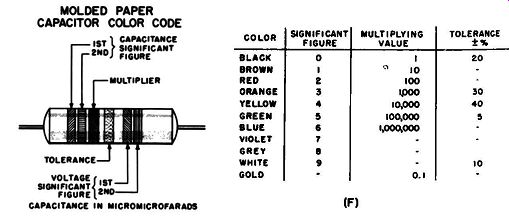
Fig. 4-1 (F). Color code for small paper tubulars.
Types. The basic capacitor construction just described is used in low-voltage applications throughout the audio-frequency range and for the lower radio frequencies. It is known as the noninductive construction. Since the various turns in each of the plates are all connected, no part of either plate extends for any distance beyond the terminal, and inductance effects are negligible.
There is another type of construction which can be manufactured at lower cost. In this type, shown in Fig. 4-1 (C), the foil is narrower than the insulating paper layer, and the terminal is connected to only one small part of the foil. Thus a considerable length of each foil strip extends away from the terminal, and inductance and resistance effects take place. Since the two foils are coiled about each other, the inductance effect is increased. This capacitor construction is known as the inductive type. Since inductance effects cause increasingly high inefficiency with rising frequency, this type of construction is restricted to applications at sub-audio- and low audio-frequencies.
In another paper capacitor, known as the metalized type, aluminum is deposited upon the paper in layers which are a small fraction of a millionth of an inch in thickness. Because of the extreme thinness of the plate, the capacitor has self-healing characteristics when voltage breakdown takes place through the dielectric.
A spark through the paper usually destroys the thin plates for a small distance around the sparkover region, and no further breakdown can take place through the insulation at that particular point. Due to this self-healing characteristic, a single layer of paper can be used between the plates for voltages up to 200. This saving in insulation thickness and foil thickness results in an overall capacitor size which is well below one-half that of conventional foil capacitors. At higher operating voltages several layers of paper must be used between the plates, and some of the size advantage is lost. In some metalized constructions, plastic film is used instead of paper.
When paper capacitors are required to have a capacitance of over 1 µ.f, their physical size generally becomes too large for convenient mounting. Under such conditions, the capacitor is placed in a metal case which is filled with insulating material and then hermetically sealed. Units of this type are shown in Fig. 4-1 (D) and are known as potted or bathtub capacitors. Special brackets, or screws through holes in tabs on the base, or clamps provide secure mounting. Metal-encased construction, see Fig. 4-1 (E), is used for units of smaller capacitance when a heavy-duty unit is required for use under conditions of high temperature, high surge voltage, excessive moisture, and severe mechanical vibration.
When paper tubular capacitors are too small for convenient letter symbols to be used to indicate the various ratings, a color code, as shown in Fig. 4-1 (F), is used.
Commercial types. A survey of the various types of commercial paper capacitors is shown in Table 4-1 and the accompanying illustrations. Included in the table are typical sizes and operating characteristics. Note that voltage ratings are generally in terms of d-c working voltage. While d-c working voltage ratings are based on dielectric strength, a-c ratings require consideration of frequency and power factor, since these determine the amount of heating which takes place within the body of the capacitor. In most electronic-equipment applications, paper capacitors are used in filter circuits, bypass circuits, and as signal coupling devices. In these situations, the a-c component is only a very small part of the applied d-c voltage, and there is generally no heating problem caused by the a-c component. If the capacitor is to be used in circuits where there is a high a-c component, such as in power supply resonant-filter networks, tests should be performed to en sure that the specified maximum operating temperature is not exceeded. A very rough rule of thumb is that the a-c voltage should not exceed 15% of the dc rating for frequencies between 100 hz and 60 hz. At frequencies in the region of 10,000 hz the a-c voltage should not exceed 1% of the d-c rating.
----------------------
R-L-C COMPONENTS HANDBOOK TABLE 4-1 Paper Capacitor
Description: Working voltages dc:
Capacitance range: Body size range: Description: Working voltages dc:
Capacitance range: Body size range: Description: Working voltages dc:
Capacitance range: Body size range: Description: Working voltages dc:
Capacitance range: Body size: Description: Working voltages dc:
Capacitance range: Body size range: Description:
Working voltages dc: Capacitance range: Body size range: Description: Working voltages dc: Capacitance range: Body size range:
---
Microminiature
Tubular microminiature, metalized-paper construction 200, 400, 600 200 volts-0.005 to 0.10 µf; 600 volt-0.0005 to 0.0068 ,.1 200 volt, min. cap.-7/16 X 3/16 in.; 600 volt, max. cap. 9/16 X ¼ in.
Subminiature Tubular subminiature, metalized-paper construction, metal encased, operates up to 125° C 200, 400, 600 200 ,·olt-0.10 to 6.0 µf; 600 volt-0.01 to 1.0 µf 200 volt. min. cap.-13/16 X 5/16 in.; 600 volt, max. cap. 1 13/16 X 1 in.
Standard Tubular
Standard tubular, cardboard wrapping, wax-coated, treated-paper dielectric 200, 400, 600, 1000, 1600 200 volt-0.0001 to 1.0 µf; 1600 volt-0.0001 to 0.05 µI 200 volt, min. cap.-1¼ X ¾ in.; 1600 volts, max. cap. 2¼ X 15/16 in.
Molded Tubular Standard-type tubular construction molded in Bakelite jacket. Larger sizes oil impregnated.
400, 600, 1000 400 volt-0.001 to 1.0 µf; 1000 volt-0.001 to 0.068 µf 400 mlt, min. cap.-1 x 5jl6 in.; 1000 volt, max. cap. 1% X ¾in.
Bathtub Case Oil-impregnated paper capacitor encased in rectangular metal case with rounded corners. One, two, and three capacitors in common case available in most voltage ranges.
100,200,400,600, 1000 100 volt-1.0 to 4.0 µf; 1000 volt-0.05 to 1.0 p.( 100 volt, min. cap.-1 13/ 16 X 1 x 3/8 in.; 1000 volt, max. cap.-2 x 2 x 1 ¼ in.
Small Rectangular Case Oil-impregnated paper capacitor encased in rectangular metal case with square corners. One, two, and three capacitors in common case available in most voltage ranges.
400, 600, 1000, 1500 400 volt-0.1 to 1.0 µf; 1500 volt-0.01-0.01 to 0.05-0.05 µf 400 volt. min. cap.-1 5/16 X ¾ X 11/16 in.; 1500 volt, max. cap.-1 5/16 X ¾ X 2 in.
Large Rectangular Case Oil-impregnated paper capacitor encased in rectangular metal case with square corners. Single capacitors only.
600, 1000; 1500; 2000; 2500; 3000; 4000; 5000; 6000; 7500; 10,000; 12,500 600 volt-0.25 µf; 2500 \Olt-0.I µf to 2.0 µf 600 volt, min. cap.-1 13/16 X 1/16 XI¾ in.; 12.500 volt, max. cap.-13½ X :>1/s X 13¾ in.
--------------------
MICA CAPACITORS
Basic construction. The basic construction of a mica capacitor is shown in Fig. 4-2 (A). It consists of a number of flat strips of metal foil separated by similarly shaped strips of mica. The foil strips serve as the capacitor plates, and the mica acts as the dielectric. Alternate plates are connected together. An electrode is attached to each set of plates, and a terminal or lead wire is connected to each electrode. Then the entire construction is encased in a container of plastic insulating material. In manufacture the total capacitance can be increased by enlarging the area of the individual plates, by increasing the number of plates, by using thinner mica strips to decrease the distance between the plates, or by a combination of all three methods.
The accuracy with which the total capacitance can be pre determined in the manufacturing process depends upon the precision with which the plates can be cut to the desired area and the accuracy with which the mica can be split to the required thickness. In actual practice, the mica and foil plates c-an be cut to size with an accuracy of 0.001 inch, and it is not unusual for the mica plates to be split with accuracy into layers of 0.0005-inch thickness.
An alternate construction is that of the "silvered" mica capacitor. In this construction very thin layers of silver are deposited directly upon one side of the mica, and the plates are stacked together so that alternate layers of silver are separated by alternate layers of mica. The result is the equivalent of the foil construction. This method enables closer manufacturing tolerances to be met, since precision masking techniques permit the area of the deposited plate to be determined with greater accuracy and greater uniformity than in the cut-foil construction. In addition, the thickness of the completed capacitor is less, due to the thinness of the deposited plate.
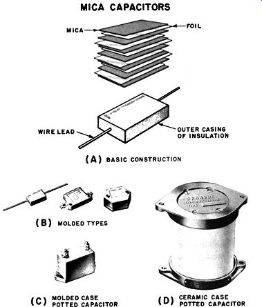
Fig. 4-2. Mica capacitor. (A) Basic construction. (B) Molded types. (C) Molded
case potted capacitor. (D) Ceramic case potted capacitor.
MICA CAPACITORS MICA WIRE LEAD OUTER CASING OF INSULATION (A) BASIC CONSTRUCTION ( B) MOLDED TYPES ( C) MOLDED CASE POTTED CAPACITOR ( D) CERAMIC CASE POTTED CAPACITOR
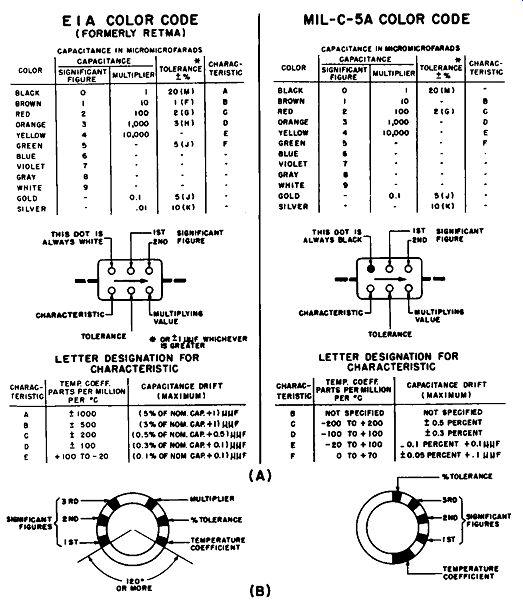
Fig. 4-3. Mica capacitor color coded. (A) Rectangular mica. (B) Button mica.
Characteristics. The construction of mica capacitors results in unusually good permanency of physical dimensions. In addition, the electrical and physical characteristics have great stability throughout the entire temperature range normally found in electronic equipment. Voltages as high as 5000 fail to break down a layer of quality mica only 0.001 inch thick. Mica exhibits high insulation resistance and high Q, making it suitable for capacitor applications involving high a-c currents and high frequencies.
There are three basic types of mica capacitors which are commercially available. Molded capacitors, Fig. 4-2 (B), are those in which the stack of plates and dielectric are molded directly into the case material. When the stack is surrounded by insulating material contained within a molded case, the construction is known as a molded-case potted capacitor. See Fig. 4-2 (C). The third construction is almost identical to the second except that the outer case is made of ceramic material. This type is known as a ceramic-case potted capacitor, Fig. 4-2 (D). When the case design of these various types does not permit stamping the various capacitor ratings on the outside, a color code, as shown in Fig. 4-3 (A), is used. Interest in miniaturization has led to the development of a small mica capacitor shaped in the form of a button. Two methods of color coding this type are shown in Fig. 4-3 (B). Characteristics of typical commercial mica capacitors are shown in Table 4-2.
-----------------
TABLE 4-2 Mica Capacitor
Description: Working voltages dc: Capacitance range: Body size range: Description: Working voltages dc: Capacitance range: Body size range: Description: Working voltages dc: Capacitance range: Body size range: Description: Working voltages peak ac: Capacitance range: R-f current range: Body size range:
Description: Working voltages peak ac: Capacitance range: R-f current range: Body size range:
---
Small Molded
Small rectangular molded case, foil or silvered mica construction, wire leads, mounted by wire leads. Wide range of capacitance values in identical body size; largest.
Ear Mounting
Molded phenolic case, rectangular shape with phenolic mounting ears, solder terminals. Wide range of capacitance values in identical body size.
Semi-hexagonal Molded phenolic case, semi-hexagonal shape; ends have tubular metal inserts, threaded or unthreaded, which serve as terminals. Wide range of capacitance values in identical body.
Potted Molded Case
Mica stack potted in low-loss phenolic case.
Case is rectangular with phenolic mounting ears and threaded terminals with two nuts. Only two body sizes
Potted Ceramic Case
Mica stack potted in glazed ceramic cylinder with cast aluminum end bell terminals. Designed for transmitter applications. Wide range of capacitance values in four standard body sizes
-----------------
ELECTROLYTIC CAPACITORS
(A) WET TYPE ( B) DRY TYPE
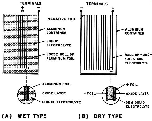
Fig. 4-4. Electrolytic capacitors, amplified construction.
(A) Wet type. (b) Dry type.
When capacitances of more than 1 µ.f are required, the size and cost of a suitable paper capacitor becomes prohibitive for all but very special applications. Electrolytic capacitors are used in such cases, since they provide capacitances to several thousand microfarads at reasonable size and cost. Electrolytic capacitors are generally suitable only for circuits in which a d-c voltage is applied across them. Special types are available for use in applications in which d-c voltage of changing polarity may be applied. Other special types may be used in a-c applications, such as motor starting, in which a-c voltage is applied intermittently. Although electrolytic capacitors are available in a large variety of sizes, shapes, and special ratings, there are only two basic types of construction used--the obsolete wet and the present-day dry types. The principles of operation of both these types are practically identical.
Basic construction. The basic construction of a wet electrolytic capacitor is shown in Fig. 4-4 (A), and the construction of the dry type is shown in Fig. 4-4 (B). The anode (positive plate) is a rolled strip of aluminum foil or cotton gauze sprayed with aluminum.
The dielectric material is a layer of aluminum oxide formed upon the surface of the anode. The thickness of the oxide layer is only a few hundred thousandths of an inch, and the dielectric constant of this oxide is approximately 10. In the wet construction the rolled anode with its oxide layer is immersed in a liquid electrolyte.
In the dry construction the anode is rolled together with a similar but uncoated negative plate, and the electrolyte is either a very thick liquid or a paste. In the most common present-day constructions, a gauze or paper layer is saturated with liquid electrolyte, and this semisolid electrolyte is placed between the two metal plates. A vent is used in the container of the wet type to allow gas bubbles to escape, and most dry types have a closed vent which opens if excessive gas pressure develops in the sealed container. The electrolyte is in very close contact with both the oxide layer and the container, and the electrolyte serves the function of the negative plate (cathode) of the capacitor. The aluminum container of the wet type serves as the negative terminal and provides an electrical contact between the electrolyte and outside circuits. This same purpose is served by the negative plate of the dry type.
Since the dielectric material, the oxide layer, is extremely thin and has a high dielectric constant, the construction yields an extremely high capacitance. When the oxide layer is formed on plain aluminum foil, the effective area of the anode plate is the actual area of the aluminum surface. If the surface of the foil is etched by chemical treatment or if the plate is made of cotton gauze sprayed with aluminum, a vast quantity of tiny holes are formed in the surface, and the effective area of the anode is greatly increased -- hence a much higher capacitance in the same space.
Because the construction of an electrolytic capacitor makes it difficult to control the thickness of the dielectric and the total area of the anode plate, fairly loose tolerances of total capacitance are allowed by military specifications. In general, an electrolytic capacitor is acceptable if its actual capacitance is no less than 90% or more than 250% of its rated value.
The construction of an electrolytic capacitor makes it quite economical to place several anode plates inside a single casing.
Thus a common case with a single negative terminal and the same electrolyte material serves for all the anode plates in the unit. Each anode has its own positive terminal. Commercial units are commonly available with two and three anodes at the same or different total capacitance and voltage ratings.
CHARACTERISTICS
Voltage characteristics. Within the rated operating temperature range the dc working voltage rating of an electrolytic capacitor is that dc voltage which can be applied continuously across its terminals without breakdown. The peak working voltage rating represents the sum of the dc working voltage and peak a-c voltage that may he applied continuously across the terminals. A surge voltage rating is often given; this represents the maximum dc voltage that may he applied for a short period. Typical relation ships between dc working voltage and surge voltage are shown in Table 4-3.
Dc leakage current. Commercial and military specifications establish the maximum leakage current that may flow through an electrolytic capacitor after the d-c working voltage has been applied.
This leakage current is usually limited to either below 10 ma or below that given by the formula listed below-whichever is smaller: Maximum leakage current= KHZ + 0.3 , where C is the capacitance as rated in p.f and K is a constant as given in Table 4-4.
---------------
TABLE ,.3
Working voltage (dc) Surge voltage (dc)
15 25 50 100 150 200 250 300 350 400 450
20 40 75 150 200 250 300 350 400 450 500
-----------
TABLE 4-4
TABLE 4-5
Equivalent series resistance. Leakage current, in itself, does not clearly indicate the power loss resulting from the use of a particular electrolytic capacitor. A knowledge of the equivalent series resistance is also required. The equivalent series resistance in an electrolytic capacitor is an expression of the total effect of electrolyte resistance, the contact resistance between the various materials, and the dielectric resistance. The power losses of an electrolytic capacitor are expressed as the equivalent series resistance multiplied by the square of the leakage current. Military specifications for electrolytic capacitors provide a maximum permissible value for equivalent series resistance and thus effectively establish a limit to acceptable power loss. The relationship used is put in a form which makes it applicable to all capacitance values. According to this relationship, the product of the equivalent series resistance and the capacitance (in microfarads) shall not exceed the P value shown in Table 4-5. Measurements of series resistance should be made with a polarized capacitance bridge at a frequency of 120 hz.
Commercial types. The various types, sizes, and other characteristics of commercial electrolytics are indicated in Table 4-6.
Non-polarized electrolytics. In the electrolytic capacitors described above, permanent damage results if the polarity of the applied voltage is ever reversed, even if that reversal is only for a few seconds. In addition, the ac component in the applied voltage must always be low with respect to the dc component so that the anode is never driven negative with respect to the cathode.
Certain other types of electrolytic capacitors are available for applications where the dc polarity may shift or ac voltage is applied.
In such capacitors, the negative plate is replaced with another anode plate.
--------------------
TABLE 4-6 Electrolytic Capacitor-Aluminum Foil Type
Description: Working voltages dc: Capacitance range: Body size range: Temperature range:
Description: Working voltages dc: Capacitance range: Body size range: Temperature range: Description: Working voltages dc: Capacitance range: Body size range: Description: Working voltages dc: Capacitance range: Body size range:
Midget Axial-Lead Tubulars Aluminum container with waxed cardboard outer wrapping. Axial insulated or bare wire leads. Dual section types in common case are available. Mounted by leads or body clamp 6, 12, 15, 25, 50, 1!">0, 2:i0, 350, 450, 475, 500 6 volt-50 to 2000 µ.f; 500 volt-8 to 20 µ.f 6 volt, min. cap.- 1 1/4 in. long X ¾ in. diam.; 500 volt, max. cap.-2¼ in. long X 1 in. diam.; dual-section 40 + 40 µ.f at 450 wv dc-3% in. long X 1 in. diam. 85°C, max. operating temperature for 6 to 450 wv dc sizes; 65°C, max. operating temperature 475 to 500 wv dc
Axial-Lead Tubular
Same as midget type, except that all have flexible insulated leads and all arc mounted by body clamps. Dual and triple-section types available 150, 250, !150, 450 150 volt-10 + 10 to 50 + 50 u.f dual section; 450 volt 10 + 10 to 40 + 40 u.f dual section 150 volt, min. cap.-2¼ in. long X 11/16 in. diam.; 450 volt, max. cap.- 1 ¾ in. long X 1 ¼ in. diam.
65°C , max. operating temperature
Screw-Down Type Tubular aluminum case with threaded neck at one end.
Neck fits through chassis hole and is held by ¾·16 or 1/g-16 nut. Color-coded flexible leads extend from neck. Color code marked on case. Case insulated from capacitor.
Single, dual, and triple sections available 450 (525-volt surge), 475 (600-volt surge), 600 (800-volt surge) 450 volt-4 to 40 u.f, 16 + 16 u.f dual, 8 + 8 + 8 triple; 600 volt-4 to 16 u.f 450 volt, min. cap.-2 7 / 16 in. long X 1 ¼ in. diam.; 600 volt, max. cap.-4 7 / 16 in. long X 1 ½ in. diam.
Twist-Prong Type
Tubular aluminum case with ll or 4 mounting prongs at one end. Prongs fit through metal or Bakelite mounting plate and arc twisted to hold capacitor. Solder lug terminals located between mounting prongs serve as common negative terminal. Single to quadruple sections available in wide assortment of capacitance and voltage combinations 6 volt, single section, max. cap.-2000 u.f; 500 volt, single section, max. cap.-15 u.f; 450 volt, quadruple section, max. cap.-40 + 20 + 10 + 10 u.f
6 volt, single section, max. cap.-2 in. long X 1 ¼ in.
diam.; 500 volt, single section, max. cap.-2 in. long X 1 in.
diam.; 450 volt, quadruple section, max. cap.-2 in. long X 1 ¼ in. diam.
-------------------
The most common application for these is in connection with capacitor-start a-c motors. In this type of service, a-c voltage is applied across the capacitor for about ½ second or less. Once the motor is started, the capacitor is switched out of the circuit by a speed-controlled switch within the motor itself. Such capacitors are available in capacitance ratings of from 50 to 500 µ.f and are intended for use with 60-cycle, 110-volt motors. Since the capacitor is heated by the ac voltage during each start, these types should not be used in applications where the motor is required to start more often than once every three or four minutes.
Very small a-c motors, rated at 25 to 50 volts at 0.01 horse power or less, require that the capacitor be connected across the a-c voltage for the entire time the motor is operating. Electrolytic capacitors are available in sizes from 10 to 75 µ.f for continuous duty in such applications.
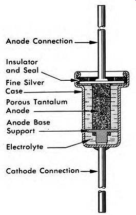
Fig. 4-5. Construction of tantalum electrolytic capacitor.
Tantalum electrolytics. The operation and basic construction of tantalum electrolytics are similar to aluminum electrolytics. A typical example is shown in Fig. 4-5. The major difference is that tantalum is used for the anode plate material and tantalum oxide serves as the dielectric. The anode may take the form of a porous plug, a curved or flat plate, or a network of wires. Until recently the higher cost of tantalum as compared to aluminum electrolytics has restricted their use. The reason has been the cost of the basic materials and the special construction required because of the corrosive action of the electrolyte.
Basic advantages of tantalum electrolytics have been that tantalum oxide has a higher dielectric constant and a lower leakage current than aluminum oxide. The need for subminiature electrolytics for use in transistor applications and the need for electrolytics that will maintain their performance at high temperatures have both led to the commercial development of the tantalum construction. This, in turn, is leading to the widespread use of tantalum electrolytics in special applications, in spite of appreciably higher cost as compared to aluminum electrolytics.
Present-day tantalum electrolytics are of two general types: One type is extremely small and is intended for use in applications involving subminiature circuitry. They maintain their characteristics at operating temperatures from -55°C up to +85°C and have leakage currents of less than 0.1 ma/volt/u.f. Special variations with silver outer cases have even lower leakage currents. Sub miniature tantalum electrolytics are generally available with axial leads. Typical dimensions and ratings are shown in Table 4-7.
The second type of tantalum electrolytic is designed for use under wide extremes of operating temperature range (-55°C to +200°C) and under conditions where resistance to corrosion and mechanical shock are required. This type is generally constructed with a steel outer case with hermetic sealing and with terminals instead of wire leads for making electrical connections. Typical dimensions and ratings arc shown in Table 4-8.
-------------------
TABLE 4-7
Tantalum Electrolytics-Subminiature Type
Description:
Working voltages dc:
Capacitance range:
Body size range:
Operating temperature range:
-------------------
TABLE 4-8
-------------------
Description: Working voltages dc:
Capacitance range:
Body size range:
Operating tempera ture range:
Tubular metal-case units with radial or axial leads. Case insulated or uninsulated. Construction details, sizes, and ratings differ with manufacturers. Nonpolarized types available About two dozen working voltages from 0.5 volt to 150 volts
Tubular or rectangular metal-case units. Case insulated.
Construction details, sizes, and ratings differ with manufacturers. Nonpolarized types available
About two dozen working voltages from 10 volts to 600 volts
Extreme operating temperature range available- - 55°C to+ 200°c
-------------------
CERAMIC CAPACITORS
Fixed ceramic capacitors are available in a wide variety of sizes and shapes, and various special types are available for special purposes. Fixed ceramic capacitors are frequently used in vhf and uhf applications and are particularly useful in applications which require extremely high working voltage and low or precisely known temperature coefficient.
Fig. 4-6. Basic types of ceramic: capacitors. (A) Fixed tubular. (B) Adjustable disc. (C) Fixed disc. (D) Adjustable tubular. (E) Stand-off. (F) Feed-thru. (G) High Voltage.
Basic construction. Although ceramic capacitors are available in a number of basic shapes, including the tubular, adjustable tubular, stand-off, feed-through, disc, adjustable-disc, and high voltage types shown in Fig. 4-6, they all have the same basic construction. Even in many of the newer shapes, including collar button, pin-head, shirt-stud, and metal-cup shapes, the construction is basically the same. This basic construction, shown in Fig. 4-7, consists of a ceramic disc or tube with silver or copper plates dc posited on the opposite faces of the ceramic material. In the manufacturing process, electrodes are attached to the plates, leads or terminals are fastened to the electrodes, and a moisture-proof coating of plastic or ceramic is added.
Effects of ceramic used. As is the case with all capacitors, the total capacitance of a ceramic capacitor is determined by the area of the plates, the distance between the plates, and the dielectric constant of the ceramic dielectric material. The type of ceramic material used determines the special characteristics of the capacitor.
Steatite ceramics have a dielectric constant (K) in the region of 6, magnesium titanate has a K in the region of 16, and barium titanate has a K of approximately 1200. When the dielectric constant is below 500, the ceramic material is considered to be of the low-K type. If the K is above 500, the dielectric material is considered to be of the high-K type. Use of low-K ceramics results in a capacitor which has good stability with regard to temperature and voltage changes. Although use of high-K ceramics results in greater capacitance without a size increase, there is a loss in the stability of the capacitance with regard to voltage and temperature changes.
Characteristics. According to the type of dielectric used, ceramic capacitors may be divided into three main types with several additional specialized types. The first is a general-purpose type generally intended for the replacement of mica and paper capacitors in bypassing and coupling applications. Such replacement is often desirable since ceramic capacitors have lower losses for vhf and uhf signals and higher insulation resistance than capacitors with paper or mica dielectrics. These capacitors are commercially available in capacitances from 10 to 5000 ,-,.u.f and in tolerances of ±20%. Details concerning the temperature coefficient are not stated for this type.
The second type has a precisely specified temperature co efficient. Most commercially available varieties have negative temperature coefficients of 470 or 750 parts/million/deg. C. These are particularly useful as compensating capacitors in tuned circuits which have a positive temperature coefficient and tend to change frequency during warmup. The compensating capacitor decreases its capacitance with rising temperature, and a decrease in temperature causes a capacitance rise-thus helping to correct the frequency drift in the tuned circuit.
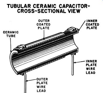
Fig. 4-7. Tubular ceramic capacitor, simplified construction diagram.
TUBULAR CERAMIC CAPACITOR CROSS-SECTIONAL VIEW
I-f transformers and other precision circuits often require a constant capacitance which is not affected by a temperature change.
In such applications the third type of ceramic capacitor is useful, since these have a zero temperature coefficient. As the equipment warms up, the capacitor temperature rises, but its total capacitance remains unchanged.
Ceramic capacitors with a precisely specified positive temperature coefficient are useful as compensating capacitors in special applications in which the other circuit components exhibit lowering values of capacitance as the temperature rises. This type is used in special-purpose equipment and is generally available only on special order from the manufacturer. Another special type of ceramic capacitor includes those in which an extremely high di electric strength is important, rather than close capacitance tolerances. These are used as power-supply filter capacitors in TV systems and are designed to have a capacitance in the order of 500 µ.µ.f at a working voltage of 20,000 volts dc.
Color code. The total capacitance and other special characteristics of a ceramic capacitor are frequently stamped on the body.
However, a color code is sometimes used, details of which are shown in Fig. 4-8.
Stamped types often have a code to indicate the temperature coefficient. There arc two symbols in common use, and these indicate the possibilities of other variations. A marking of NPO (or a black band or dot) indicates a negative-positive-zero characteristic; that is, the temperature coefficient remains essentially zero over a wide range of temperatures (usually from -20°C to +85°C). A marking of N470 or N750 (blue or violet marks) indicates that the capacitor has a negative temperature coefficient equal to 470 or 750 part/million/deg. C, respectively.
Commercial types. Table 4-9 summarizes the commonly avail able ceramic capacitors and their most outstanding characteristics.
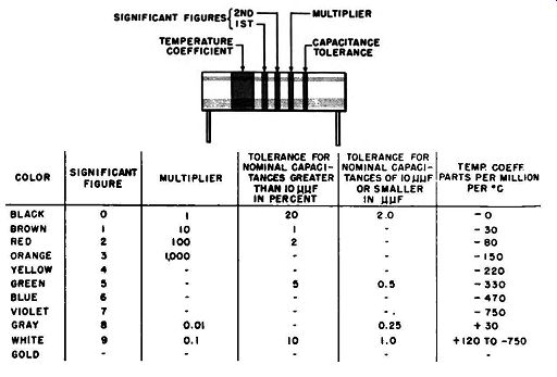
Fig. 4-8. Ceramic capacitor color code.
VARIABLE AND ADJUSTABLE CAPACITORS
The difference between variable and adjustable capacitors is similar to that between variable and adjustable resistors. When the capacitor adjustment must be made available to the equipment operators, as in tuning a radio receiver, a variable capacitor is used. On the other hand, if the capacitor adjustment is intended for use by the equipment manufacturer or service technician, as in adjusting the frequency of i-f transformers, an adjustable capacitor is installed. The major difference between the two types is the degree of convenience provided for making the capacitor adjustment.
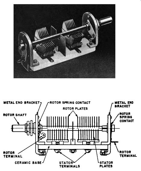
Fig. 4-9. Variable capacitor construction.
------------------
TABLE 4-9 Ceramic Capacitors
Description: Temperature coefficients: Working voltages dc: Capacitance range: Body size: Description: Temperature coefficients: Working voltages dc: Capacitance range: Body size: Description: Ratings: Body size range:
Disc Type
Thin circular discs with insulating coat. Parallel wire leads. Single-, dual-, and triple-section types Available with unspecified (general purpose), zero, and negative (-750 ppm/°C) temperature coefficients. High-K types available 500 volts (1000-volt test) for most types; 1000-volt and !1000-volt types available.
----------------------
Variable capacitors. A typical variable capacitor is shown in Fig. 4-9. A shaft, frequently mounted in ball bearings to provide smooth turning action, is provided for making the capacitor adjustment. The capacitor is generally mounted so that the shaft protrudes through the front panel of the equipment. A knob is attached to the end of the shaft to permit ease of turning. A pointer and dial are often added to permit the operator to estimate the required adjustment. Frequently a special drive and pointer arrangement is attached to the shaft, as on the more expensive home radios and communications receivers, so that very fine capacitor adjustments can be made with great ease and accuracy.
Adjustable capacitor. Typical adjustable Capacitor are shown in Fig. ~- In these types the major design stress is laid upon compact and economical construction rather than ease of adjustment. The design generally provides for adjustment by means of a screwdriver, and the accuracy of the adjustment depends upon the skill and understanding of the technician rather than special attachments.
VARIABLE CAPACITORS
Basic construction. As in all capacitors the capacitance of variable or adjustable capacitors is determined by the area of the plates, the spacing between the plates, and the type of dielectric material used. The total capacitance may be varied by changing any of these factors. Although changing the dielectric presents major problems, it is a simple matter to vary the plate area or the distance between plates.
BASIC GANGED CAPACITOR CONSTRUCTION-GROUNDED STATOR
(A) TWO IDENTICAL GANGS (B) THREE IDENTICAL GANGS (C) TWO DIFFERENT GANGS
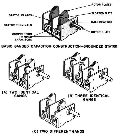
Fig. 4-10. Grounded stator construction. (A) Two identical gangs. (B) Three
identical gangs. (C) Two different gangs.
Figure 4-9 shows a typical construction for a variable capacitor.
One set of plates is mounted upon a base of insulating material which is fastened between metal end brackets. These plates are electrically connected together by a strip of metal, but there is no electrical connection between them and the metal end brackets.
The plates are fixed in position and are known as stator plates.
Another set of plates is mounted upon the metal shaft of the capacitor and is connected together electrically through that shaft.
When the shaft is turned, these plates rotate with the shaft and are therefore known as rotor plates. Although the rotor plates are electrically connected to the metal end brackets of the capacitor through the bearings, the lubricant in the bearings prevents a zero resistance path to the frame. Separate terminals, therefore, are usually provided for making electrical connections to the rotor and stator plates. Contact between the rotor and its terminal is generally provided by one or more springs which press on the rotor shaft. The construction which has been described is intended for use in transmitter applications, where high voltages are applied across the rotor and stator terminals, or in instrument applications, where minimum dielectric losses are required. A more economical construction is used in radio broadcast-band receivers. In this construction (see Fig. 4-10) a one-piece metal frame takes the place of the end brackets and base. The stator plates are mounted on the frame by strips of Bakelite or similar insulation. Springs are used to make a low-resistance path between the rotor and the frame. Since the frame is fastened to the equipment chassis or front panel, connections to the rotor do not require a separate terminal but are made simply by circuit connections to the chassis.
Since the metal plates and framework expand as the tempera ture increases, the capacitance changes with temperature. Although this change may be corrected by a slight adjustment of the shaft, this is sometimes undesirable. Capacitance changes of this type may be minimized by using Invar metal, which has a very low coefficient of expansion, for the metal parts of the capacitor.
Aluminum, plated brass, and even plated steel are the more commonly used metals in capacitors for commercial equipment.
Range of adjustment. When the shaft of a variable capacitor is turned so that the rotor plates are completely intermeshed with the stator plates, the opposed areas of the two sets of plates are at maximum, and the capacitance is at maximum. The total capacitance may be reduced by turning the shaft so that the rotor plates are only partly intermeshed with the stator plates. Since only the intermeshed areas are effective, the total capacitance is thus reduced. When the shaft is turned so that the rotor plates are completely out of mesh with the stator plates, the capacitance is at a minimum but not at zero. This is because there is a small residual capacitance; the ends of the rotor and stator plates are still close together and have the effect of plates of small area.
In addition, there is a small amount of capacitance due to the proximity of the rotor plates and terminal to the metal frame of the capacitor. Because both the maximum and minimum capacitance are of interest to the equipment designer, manufacturers of variable capacitors usually list both these values in their specifications. Although the maximum value of the capacitance can be increased by including more stator and rotor plates in the construction and by increasing the areas of those plates, there is also an increase in the minimum capacitance.
Ganged capacitors. In a number of applications, such as radio receivers, several variable capacitors are required, and all must be adjusted each time the equipment is tuned. Instead of providing separate variable capacitors, each with its own tuning shaft, the various capacitors are usually mounted together in the ganged construction shown in Fig. 4-10. Turning the shaft varies all sets of rotor plates simultaneously. Ganged capacitors are commonly available with two, three, and even four sections, and, as required by the application, the individual sections may have almost identical or completely different maximum and minimum capacitances.
Trimmers. Capacitor manufacturers cannot supply variable capacitors which are absolutely identical. Consequently the equipment engineer must include in his circuit additional adjustable capacitors (or inductors) to provide a means for adjusting the circuit capacitance to exactly that required by the application.
A trimmer is a small adjustable capacitor which is attached to the frame of the variable capacitor. In a ganged capacitor each section is frequently supplied with a trimmer, which usually consists of a small number of flexible metal plates separated by thin sheets of mica. A screw adjustment provides a means for applying pressure to the plates so that the distance between them may be decreased and the capacitance increased.
One set of trimmer plates is connected to the main rotor plates, and the other is connected to the stator plates. Thus the capacitance of the trimmer is added to that of the main capacitor.
Since the maximum capacitance of the trimmer is only a few times greater than the minimum value of the main capacitor, adjusting the trimmer has a negligible effect on the maximum capacitance of the entire unit. However, adjusting the trimmer provides an effective method for increasing the absolute minimum value of the variable capacitor to any convenient minimum capacitance which is within the adjustment range of the trimmer.
Slotted plates: In some applications it is desirable to be able to adjust the capacitance of a variable capacitor at several points over the entire tuning range. These adjustments are made possible by the slotted plate construction. In this arrangement, the two outer rotor plates are made with several slots. The portions of the plates between the slots can be pressed inward to increase the capacitance or bent outward to decrease the capacitance. The amount of bending should be kept small enough so that the bent section does not touch the frame or stator plates at any point throughout the rotation of the shaft. Since several slots are provided, different sections of the rotor plate may be bent inward or outward in any desired combination, and a wide range of small adjustments can be obtained over the entire range of shaft rotation.
Plate shape. Different applications require different percent ages of capacitance change per degree of shaft rotation. The desired variation can be obtained by shaping either or both the rotor and stator plates. While there are an indefinite number of possibilities, the three types shown in Fig. 4-11 are the most common. Part (A) shows a capacitor with semicircular rotor and stator plates. The capacitance variation of this type is such that equal changes in shaft rotation cause equal changes in capacitance.
Thus there is a linear relationship between shaft rotation and capacitance, and this type of plate shape is known as the straight line-capacitance (SLC) type.
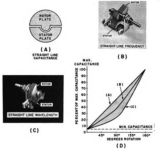
Fig. 4-11. Change of capacitance with plate shape. (A) Straight-line capacitance.
(b) Straight-line frequency. (C) Straight-line wavelength. (D) Graph of capacitance.
In frequency meters and in special types of radio receivers, it is desirable to mark the capacitor tuning dial directly in terms of frequency. It is also highly desirable to have the frequency scale evenly spaced across the dial so that equal amounts of shaft rotation represent equal frequency changes. The plate shape which gives such a result is shown in Fig. 4-11 (B). It is known as the straight-line-frequency (SLF) type. It can be seen that at 90° rotation the frequency is half way between minimum and maximum, but the capacitance is at approximately 25% of its maximum value.
In wavemeters and other special devices the capacitor dial is marked in terms of wavelength, and it is desirable to have this wavelength scale vary in a linear manner with respect to shaft rotation. Figure 4-11 (C) shows the capacitor plate shape which gives this result. This is known as the straight-line-wavelength type. At 90° rotation the wavelength is midway between its two extremes, but the capacitance is at approximately 40% of its maximum value.
Capacitors used in home broadcast receivers generally have a shape which is a compromise between the shapes shown in Fig. 4-11 (B) and (C). This type has roughly a straight-line frequency characteristic when it is near maximum capacitance and a straight-line-wavelength characteristic in the minimum capacity region. The result is that the frequency calibrations at the low frequency end of the band (maximum capacitance) have wide and even spacing, while the frequency calibrations at the high frequency end of the band have a fairly even but narrower spacing.
Power factor. The power factor of variable air capacitors is very low. It is not equal to zero even though air as a dielectric has a power factor of zero. The basic reasons for this are that the insulating material which holds the rotor and stator plates in position does have dielectric losses and that the resistance of the springs and the various electrical and mechanical connections between the plates is not equal to zero. The combined effect of these is that at frequencies below 1000 khz the power factor steadily decreases as the rotor plates are turned so as to increase capacitance.
At higher frequencies the power factor decreases to a minimum value as the capacitance is increased to about 10 to 30% of maximum, and then it increases steadily as the capacitance is increased to maximum.
Voltage breakdown characteristics. The voltage breakdown characteristics of variable capacitors are determined by the spacing between the plates; if compact design is important, the thickness of the plates also must be considered. At normal atmospheric pressure, a 0.01-inch air spacing between plates will withstand approximately 1500 volts dc without sparkover. However at 50,000 feet altitude, the same plate spacing will exhibit sparkover if 400 volts dc is applied. From this example it can be seen that there is no problem of voltage breakdown in radio receiver variable capacitors designed to operate at sea level. In transmitter applications where higher voltages are applied, air gaps of 0.02, 0.03, and 0.07 inch are successfully used to withstand voltages of 800, 1200, and 1700. For aircraft applications, and particularly for aircraft transmitters operating at high frequency, note that air has a lower dielectric strength at reduced pressure. In addition, sharp edges cause concentrated voltage gradients in the electric field around the plate and cause ionization of the air in that region, which results in localized voltage breakdowns. These appear as a faint bluish glow known as corona. Corona represents a power loss even at line-voltage frequencies; and the effect, along with its power loss, increases with frequency.
Since aircraft equipment requires that minimum space be used at maximum efficiency, capacitors designed for such applications cannot be safeguarded against breakdown effects simply by increasing the air gap. Gaps must be kept small to reduce plate size, and corona effects must be eliminated by rounding all edges to prevent concentrated voltage gradients. Reducing voltage gradients also involves selecting special ratios between plate thickness and air gap. While it has been found that best results are obtained when the air gap is between two and three times the plate thickness, this is not sufficient basis for selecting capacitors for such applications. Prime consideration should be given to the manufacturers specifications for the voltage, frequency, and altitude at which his various models will operate without breakdown.
Temperature coefficient. Since all the materials used in variable capacitor construction expand as their temperature increases, plate size and spacing also change with temperature, resulting in a change of capacitance. These capacitance changes cannot be predicted with accuracy since they depend upon the exact mechanical construction of each capacitor design. The matter is further complicated by the fact that the plates may warp slightly due to twisting by uneven frame expansion and by the fact that there is also a change in the dielectric constant of the insulating material used in the construction. As a result the temperature coefficient for any particular design may be either positive or negative, and it may be anywhere in the range of from + 175 to -75 parts/million/deg. C. Careful design and production control can produce variable capacitors with zero temperature coefficient or an accurately con trolled positive or negative temperature coefficient. Such types are expensive, and in most applications satisfactory results are more economically obtained by the addition to the circuit of a temperature-compensating ceramic capacitor.
Commercial types. Variable air capacitors are available in literally dozens of construction types. Although there are miniature, medium and large types, these are variations in name only. The minimum plate area, number of plates, and air spacing are limited by the required capacitance and voltage rating, as has been described previously. The smallest capacitors in common use have three pairs of plates with a capacity range of from 3 to 15 p.p.f and an overall length of about 1 ¼ inches.
Types in common use in superheterodyne receivers have two gangs. The gang for the oscillator section has about 17 to 20 plates with a range of from 8 to 170 ,,.,,.f. The gang for the r-f section has from 25-30 plates with a capacitance range of from 10 to 450 ,,_,,_f.
Overall body size, Jess shaft, is about 1 ½ by 1 ¼ by I~~ inches.
Heavy-duty transmitter types have air gaps as wide as 0.500 inch, up to 80 plates or more, and capacitance ranges as wide as from 50 to I 200 ,,_,,.f. The largest sizes in common use have an overall length of 20 inches.
ADJUSTABLE CAPACITORS
Basic types. The most common types of adjustable capacitors, shown in Fig. 3-4, include the book-type capacitor, the ceramic-disc type, the circular metal-disc type, and the rotating-plate type.
Additional variations include sealed metal-plate capacitors in which the dielectric is compressed gas, a vacuum, or various types of oil. These types are available as fixed, adjustable, and continuously variable capacitors.
The basic construction of the book type was described in the review of the trimmer for variable capacitors. When this type is supplied as a separate unit, the metal plates are usually mounted on a ceramic base, as shown in Fig. 3-4 (A). The basic construction of the ceramic-disc type consists of a rectangular ceramic base and a circular disc of the same material. These two units are fitted together as shown in Fig. 3-4 (B) so that one face of both the base and the disc are in close contact, and the two units are held together by a center pivot. The faces in contact with each other are polished so that the circular disc may be turned with a minimum of friction. A semicircular silver plate is deposited upon the faces of the ceramic units which are not in contact with each other. The capacitance is adjusted by turning the circular disc so as to obtain the desired amount of overlap between the two silver plates. The principles involved are the same as those of a variable air capacitor with semicircular plates, as is shown in Fig. 3-4 (C). By selection of the type of ceramic material used, a degree of temperature compensation may be obtained.
In the circular metal-disc type of construction, see Fig. 3-4 (D), two circular metal plates are mounted in line with each other.
One plate is fixed and the other is mounted on the encl of a rod with a screw thread. By turning the rod, the distance between the two plates may be varied, and the capacitance is thus adjusted.
In the rotating-plate type, Fig. 3-4 (C), the construction is almost identical to that of a variable air capacitor. The principles of operation are identical, and the difference is in the type of shaft supplied. Since the adjustment is not intended for use by the equipment operator, a short shaft with a screwdriver slot is usually supplied. Sometimes there is a device supplied for locking the shaft in the selected position.
Gas, vacuum and oil types. Capacitors of the gas, vacuum, and oil types are special items sometimes used in high-power transmitters for tuning, neutralizing, and antenna coupling networks.
Although these types may be either of fixed or variable construction, they are most commonly available as adjustable types.
The internal construction may consist of rotor and stator plates similar to those in variable capacitors, or it may consist of discs with an adjustable spacing between them. The major difference is that the plates are ·mounted in a hermetically sealed container, and, instead of air, the dielectric may be compressed gas, a vacuum, or oil. The reason for such construction is that air does not have favorable dielectric strength when used with high voltages or high frequencies, as already has been considered in the review of the voltage characteristics of variable air capacitors.
When compressed gas is injected into the container, the capacitance remains essentially unchanged, but higher voltages can be applied without breakdown. Nitrogen is the gas most frequently used. At pressures of about 2000 pounds per square inch, the voltage that can be applied across the plates is about five times that of an equivalent air capacitor. Although this construction increases the cost, such cost compares favorably with that of an air capacitor with equivalent characteristics. A significant saving is also achieved in the space requirements.
In the vacuum-type capacitor, the air within the container is pumped out until a very low pressure equivalent to those found in vacuum tubes is obtained. As the air pressure is reduced inside, the remaining air is more easily ionized, and corona and sparkover occur at lower voltages. However, when a "high vacuum" is reached, there is insufficient air present for easy ionization, and the voltage rating rapidly increases. Fixed-vacuum capacitors of reasonably small size are available in a variety of capacitance and voltage ratings up to, and beyond, 200 u.u.f at 35,000 volts peak. Vacuum capacitors of the variable type have a metal bellows or diaphragm with suitable mechanical devices for moving the bellows or diaphragm inward or outward and thus changing the distance between the plates inside. The range of adjustment is not as wide as obtainable with air variables and is generally limited to the range of about 20% of the maximum capacitance. Vacuum adjustable are available in various sizes up to the region of 400 uuf with a peak voltage rating of 10,000 volts.
When a capacitor container is filled with oil, both the voltage rating and the capacitance are, increased. The improvement obtained in these characteristics depends upon the dielectric strength and dielectric constant of the particular type of oil used. A capacitance increase of from three to five times is readily obtainable.
The use of oil has advantages over compressed gas and vacuum dielectrics. Since there is no pressure differential between the in side and outside of the case, only simple seals are required. This makes it a relatively easy matter to use a rotatable shaft through the container without oil leakage, and the convenient rotor-stator construction can be achieved.