AMAZON multi-meters discounts AMAZON oscilloscope discounts
INDUCTANCE
Basic characteristics. Inductance is a phenomenon associated with the flow of electric current through wires, particularly coils of wire. Included here will be a brief review of inductance, but the major subject of this section is an analysis of the practical characteristics of inductors such as chokes, transformers, and tuning coils used in electrical and electronic equipment.
The basic cause of all inductance, as shown in Fig. 5-1 (A), is the fact that a magnetic field is produced whenever electric current flows through a wire. The magnitude of the inductance increases when the wire is wound in the form of a coil [see Fig. 5-1 (B)], and a further increase may be obtained by placing a core of iron within the coil, as shown in (C). When dc flows through a coil, the well-known electromagnet is produced. When ac flows through the coil, the result is what is known as a choke, since it has the effect of impeding the flow of ac. If another coil of wire is placed dose to the coil under discussion, as shown in Fig. 5-1 (D), an a-c voltage appears across the ends of this second coil-resulting in a transformer.
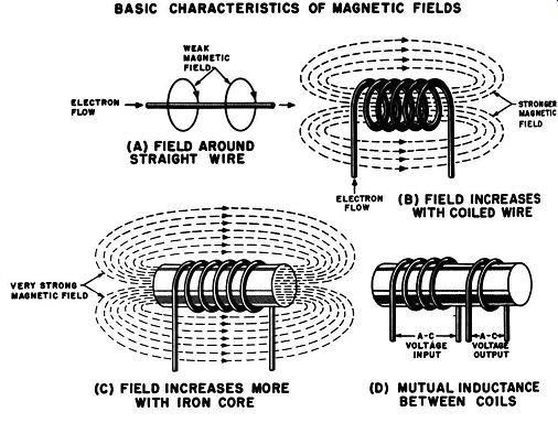
Fig. 5-1. Basic characteristics of magnetic fields. (A) Field around straight
wire. (B) Field increases with coiled wire. (C) Field increases more with iron
core, (D) Mutual inductance between two coils. (C) FIELD INCREASES MORE WITH
IRON CORE (D) MUTUAL INDUCTANCE BETWEEN COILS.
In an ac circuit the effect of a coil bears some resemblance to that of resistance in a dc circuit, but there are important differences. When ac flows through a coil, the current alternately increases to a peak, falls to zero, reverses direction, rises to a peak in this opposite direction, and then decreases to zero. The result is that the magnetic field produced increases and decreases in the same manner. Since a voltage is produced in a conductor when it is intercepted by a changing magnetic field, a new voltage is induced across the coil of the choke by its own moving magnetic field. This voltage, known as the "back emf," is always in such instantaneous polarity that it opposes the change in the current originally producing the magnetic field. The effect is known as inductance. A coil has an inductance of 1 henry if an induced voltage of 1 volt results when the current changes at a rate of 1 ampere per sec. The opposition which a coil offers to the flow of ac is known as inductive reactance and is measured in ohms.
Since a coil has a small amount of capacitance between its turns and since the wire forming the coil has resistance, a coil also exhibits small amounts of capacitive reactance and resistance.
The combined effects of inductive reactance, capacitive reactance, and resistance is known as impedance. In a well-designed coil the impedance consists almost entirely of the inductive reactance.
Chokes. In electrical and electronic equipment a choke consists of a single many-turn coil of wire. Depending upon the frequency of the ac expected to flow through the coil, it may have a core consisting of iron in various forms (to be considered shortly) or a core made of insulating materials which give mechanical support but have no intended magnetic effect or no core at all. Examples of these types are shown in Fig. 5-2 (A) and (B). The purpose of a choke is to impede the flow of ac in a circuit while offering a minimum resistance to the flow of de. In this type of application, chokes are used in a variety of power-supply filter circuits and in special filters in signal circuits. For these purposes, a choke is generally desired to have the maximum amount of inductive reactance which is compatible with size, weight, and cost requirements.
Inductive reactance can be determined from the relationship: XL= 2 pi fL , where XL is inductive reactance expressed in ohms, f is the frequency of the input voltage expressed in hz, and L is the inductance expressed in henries.
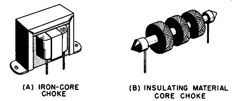
Fig. 5-2. Typical chokes. (A) Iron-core type. (b) Insulating material core
type. (A) IRON-CORE CHOKE (b) INSULATING MATERIAL CORE CHOKE.
Reference to air-core chokes has been eliminated, since they are not in common use.
From this relationship it can be seen that inductive reactance for dc is equal to zero and increases in proportion to the frequency of the applied voltage. For instance, a 1-henry choke has an inductance of just under 200 ohms at 30 hz, about 600 ohms at 100 hz, about 6000 ohms at 1000 hz, and about 6,000,000 ohms at 1 mhz.
In many applications it is desired to impede the ac component without affecting the dc component of a given current.
A resistor impedes ac and dc equally, according to the Ohms law relationship and therefore cannot be used for this purpose. however, a choke impedes ac to a high degree, according to the inductive reactance formula, while the opposition it offers to dc is equal to the very low resistance of the wire in the coil.
Transformer. When ac flows through a coil, a magnetic field is formed which continuously expands, contracts, and reverses direction. Advantage can be taken of this effect by using it to provide inductive reactance, as in the case of the chokes mentioned previously. Another type of application can be obtained by placing one or more additional coils of wire in close contact with the first. When the magnetic field expands and contracts across these nearby coils, an a-c voltage is generated across the ends of these coils, and the result is a transformer.
Transformers find widespread use as practical devices for increasing or decreasing ac voltages and for coupling circuits of widely different impedances. As in the case of chokes, the physical form of a transformer depends upon the frequency of the expected applied voltage. Thus, as shown in Fig. 5-2, transformers may consist of coils of wire wound on a core made of iron in various forms or on a core made of insulating materials which apply mechanical support only; or there may be no core at all.
In a well-constructed transformer, the following voltage relationship exists between the input (Primary) winding and each of the output (secondary) windings:
V. N.
--=--. VP
Np where v, and v. are the input and output voltages respectively, and N, and N. are the number of turns in the input and output windings respectively. When the secondary voltage is higher than that of the primary voltage, the assembly is known as a step-up transformer. When the secondary voltage is lower than that of the primary, the result is a step-down transformer.
In such a transformer the input power and the output power are equal, as indicated by the relationship: V, X1,= V. X1 , where v, and v. are the input and output voltages, respectively and 1, and 1. are the input and output currents, respectively.
Mutual inductance. In a transformer, the secondary winding is placed so that as much as desired-in most cases as much as possible--of the primary magnetic field passes through the secondary. The changes in the magnitude and direction of this primary magnetic field produce the voltage developed across the secondary winding, and thus the secondary voltage is directly proportional to the number of amperes/sec which the primary current changes. When two coils are so placed that any such coupling exists, they have what is called mutual inductance. If a change of 1 ampere/sec in the primary winding causes 1 volt to be developed across the secondary winding, I henry of mutual inductance exists in the combination of the two coils.
Leakage inductance. When a transformer is well designed, most, but not all, of the magnetic flux of the primary winding passes through the secondary winding. This effect is known as leakage inductance. Its result is to make the voltage across the secondary winding lower than that indicated by the turns ratio. This effect also limits the high-frequency response of the transformer, although the low-frequency response is affected by the mutual inductance.
Current flow and loading effects. The flow of ac through a coil produces a magnetic field which alternates in the same manner.
The expansion and collapse of the magnetic field cause it to pass through the coil and to generate a voltage known as the electro motive force ( emf) of self-induction. The emf of self-induction opposes the change in current flow. If a second coil is placed close to the first, as in the case of a transformer, an emf is induced in this second coil, and it is known as the emf of mutual induction.
Thus electric energy is transferred from the primary to the secondary. Since the emf of mutual induction opposes the current flow that is producing it, the current flow in the secondary winding is in the opposite direction of that in the primary; and the magnetic field developed by the secondary is always in the opposite direction from that in the primary.
If no load is connected to the secondary, there is an open circuit in that winding and no current can flow through it. Consequently, the secondary winding cannot develop a magnetic field which opposes the magnetic field of the primary. As a result the primary magnetic field develops maximum emf of self-induction in the primary winding. There is maximum opposition to the voltage applied to the primary and only a very small current flows in the primary. When a load is connected to the secondary, current can flow in that winding. The magnetic field produced by the secondary winding opposes that of the primary.
Therefore, the emf of self-induction in the primary is reduced, and a larger current flows in that winding. The lower the load resistance connected to the secondary, the larger the current flow in the primary. A transformer, thus, is a self-regulating device which does not draw current from the primary voltage source unless current is drawn from the secondary winding. In an ideal trans former the secondary power is equal to the primary power.
CLASSIFICATION OF TRANSFORMERS AND INDUCTORS
There are a number of methods of classifying transformers and coils, or inductors. These methods include classifications of the type of winding employed, the type of core material used, the basic overall type of construction, and the a-c frequency at which the component will be used. Methods of classification will be considered in the review of commercial transformers and inductors in Section 6.
Another method of classification is that employed in the military standards for transformers and inductors. Specification MIL-T-27, which is used in procurement of transformers and inductors for the Departments of the Army, Navy, and Air Force, considers these components by grades, classes, and families. Classification by grade divides these components into grade I-trans formers and inductors most resistant to moisture-and grade 2 transformers and inductors less resistant to moisture. According to the arrangement into classes, class A includes transformers and inductors using organic insulation, class B includes those components using inherently inorganic insulation, and class C includes those using special insulation. It is in the classification of families that transformers and inductors are listed according to function.
This listing, as shown in Table 5-1, gives a good survey of the applications of transformers and inductors.
TABLE 5-1
Family Group 01 to 07: Power Transformers and Inductors
CONSIDERATIONS AFFECTING INDUCTOR SELECTION
Although the basic interest in the selection of a coil or choke is its inductance (or its inductive reactance), the circuit designer cannot order such a unit simply on the basis of that quantity.
There are a number of other factors which must be considered.
These include Q, or figure of merit, power factor, distributed capacitance, resistance effects and temperature coefficient, corona, core losses, and others.
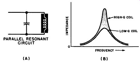
Fig. 5-3. (A) Parallel resonant circuit. (b) Impedance change with frequency.
Figure of merit. Since the purpose of a coil is to provide the maximum economical amount of inductive reactance at a particular operating frequency, it is convenient to have a figure of merit which indicates how well a particular inductor accomplishes its function. Such a figure of merit has been established and is known as Q. For inductors, Q is expressed by the relationship:
Inductive reactance at frequency of interest
XL Q = DC
resistance = R
If an inductor has a high Q, it is an indication that all the losses involved arc low, and the inductor is performing its job effectively.
For single layer coils, Q-values of several hundred are attainable
at various frequency ranges from 100 khz to 15 mhz. However, for any particular coil the Q varies with frequency because both the coil losses and the inductive reactance vary with the frequency.
The effect of Q can be seen in parallel resonant circuits, such as that shown in Fig. 5-3 (A). Such circuits are commonly used in r-f amplifiers and filter circuits. Since the coil has low reactance at low frequencies and the capacitor has low reactance at high frequencies, the circuit has a low total impedance except at the frequency where the two reactances are equal. At that particular resonant frequency, the two reactances combine to form a very high total impedance. The impedance increases to a peak at the resonant frequency, as shown in Fig. 5-3 (B) in which impedance is plotted against frequency for coils of different Q's. Note that with increasing coil losses, as represented by the coils of lower Q, the total impedance does not rise to as sharp a peak; and the combination is less frequency selective.
There are a number of methods of reducing losses, or in creasing inductive reactance, without increasing the dc resistance.
These methods include using particular wire types and diameters at various frequency ranges, using particular types of windings and coil length-to-diameter ratios, and using special core materials.
As far as the purchaser is concerned, these techniques are only of academic interest. It is the manufacturer's specifications of Q available in the various commercial. types that are of interest.
As described in the previous paragraphs, many applications require amplification of a narrow band of frequencies. This is achieved by using tuned circuits containing coils with high Q. There are a number of television and fm radio applications, however, which require the amplification of a wide band of frequencies.
This is sometimes accomplished by using coils with low Q, and the broadband amplification effect may be increased by tuning several low-Q amplifier stages to slightly different frequencies.
Measurement of Q. For equipment designers who wish to check specified values of Q or to check the Q of a custom-made coil, there is a type of instrument available known as a "Q Meter." Such a meter will measure values of Q with much greater accuracy than any complex and painstaking mathematical computation.
The instrument contains an oscillator and a built-in capacitor.
Connecting the coil to be tested to the instrument places it in a resonant circuit with the capacitor, and the output of the oscillator is connected to the resonant circuit. Contained in the instrument is a voltmeter which is connected across the capacitor. Since Q is equal to the ratio of the resonant-circuit voltage to the known oscillator voltage, the voltmeter may be calibrated directly in terms of (l.
Power factor. According to basic electrical relationships, the derivation of which will not be reviewed here, the power factor of a coil is shown by the familiar impedance triangle shown in Fig. 5-4. In this diagram R equals the d-c resistance of the coil, XL equals the inductive reactance, Z equals the resulting impedance, and (J (theta) equals the angle between the vectors R and Z .
According to the relationships shown in this diagram, Power factor = .!!-._ = cos (J
Consideration of power factor is important because it bean a very convenient relationship to Q. Q has been defined as XLfR, which is equal to the tangent of the angle (J. In well-designed coils, Z is almost equal to X,.. since R and any distributed capacitance effects are kept to a minimum. When these conditions are met, the following relationship exists between the power factor and Q:
Power factor=
This is a convenient relationship in calculations dealing with parallel resonant circuits. In this type of circuit the power factor of the complete circuit is equal to the power factor of the coil plus the power factor of the capacitor.
-------------
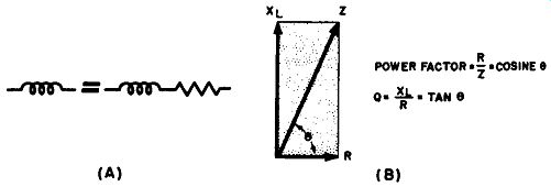
Fig. 5-4. Definition of coil power factor and Q. (A) Equivalent circuit of
inductance and resistance. (B) Impedance diagram.
-------------
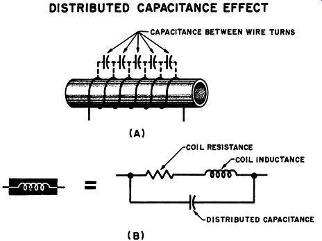
Fig. 5-5. Distributed capacitance effect. (A) Capacitance between turns. (B)
Resultant effect of coil resistance and distributed capacitance.
--------------
Distributed capacitance. When any two conductors are placed in close proximity a certain amount of capacitance exists between them, according to the relationships described in Section 3. Thus, a small amount of capacitance exists between every two turns of wire in the coil. The overall effect is that of a number of series capacitors connected in parallel at points along the entire coil as shown in Fig. 5-5, and this effect is known as distributed capacitance. Distributed capacitance is undesirable in chokes, since the capacitance offers a path for a-c signals around the choke, which is the very effect that a choke is intended to prevent. In addition, there are capacitor dielectric losses between adjacent turns in the coil, as defined in Section 3, and this represents a power loss in the coil. Since a large number of capacitors in series gives a smaller total capacitance than a small number of Capacitor in series, the distributed capacitance can be reduced by designing a coil which is long with respect to its diameter. Using thinner wire, and increasing the center-to-center distance between turns, also decreases distributed capacitance.
While these techniques are successful in reducing distributed capacitance, they do not contribute toward obtaining maximum Q. Consequently, the intended use of the coil determines the type of compromise which must be made in coil design. If the coil is for use in a tuned circuit, the compromise is almost always in favor of maximum Q and minimum coil losses with little consideration for distributed capacitance. In choke applications, it is desired to reduce distributed capacitance to a minimum, and lower Q values are sufficient.
Resistance losses and temperature coefficient. Resistance losses lower the value of Q, as described previously, and also represent a power loss in the form of heat developed by current flow through the resistance of the coil wire. In addition, when high-frequency current flows through the coil, the magnetic flux generated by the individual electrons causes them to repel each other. As a result, most of the current flow occurs in a thin layer near the surface of the wire (skin effect), thus heightening the resistance in the path of the current and increasing the heat generated. The resistance increase due to skin effect can be decreased by using a conductor consisting of a number of twisted strands of fine insulated wire, thus offering an increased surface area for current flow. Such wire is known as "litz" wire.
Because of the heat generated by the skin-effect resistance, the temperature of the coil increases when the coil is used for high-frequency currents. This temperature increase causes a change in the inductance of the coil; thus the temperature coefficient of the coil becomes important. The major reason for a temperature coefficient of inductance is that the metal of the conducting wire (and the material of the coil form) expands when heated, thus changing the dimensions of the coil and varying the inductance.
Since the wire in most coils is tightly wound around the coil form, any expansion redistributes the mechanical strains involved and produces an effect which is greater than that due solely to the expansion of the wire. Such changes in coil dimensions also affect the distance between the turns and thus affect the distributed capacitance. Heating also raises the resistance of wire, further heightening the undesirable results of skin effect. When equipment temperature stability is of primary importance, a thorough check of the various manufacturers' temperature-coefficient specifications should be made before selecting a coil.
Sparkover and corona discharge. When voltages of more than several hundred volts are applied across an inductor or exist in the windings of a transformer, it is possible for sparkover or corona discharge to take place. When the voltage is high, the electric field in the air or other insulation between adjacent coil turns or terminals may be arranged in either a uniform or nonuniform manner, depending upon the arrangement of the physical components and the insulation. Under uniform field conditions, spark over occurs, which consists simply of current flowing through the air or other insulation. Sparkover may be eliminated by greater physical separation between the ends of the sparkover gap or by the use of better insulating materials.
When the field is not uniform, particularly at places where there are points or sharp bends in a conductor, a local electrical discharge takes place, producing a faint purplish glow around the point or sharp bend. This is corona, which can be prevented by redesigning physical components, by reducing the voltage in the region of the discharge, and by special shielding techniques. Both corona and sparkover produce considerable power loss in the coil or transformer. Corona, in addition, causes local radiation at high frequencies, resulting in radio interference. Also, corona causes ionization in the surrounding air, producing ultraviolet light and ozone, both of which tend to deteriorate dielectric materials.
Military specifications generally require a corona test for inductors and transformers which are to be used in connection with high-voltage circuits. The test consists of applying a specified a-c voltage across the winding under test. If corona is present, an oscilloscope connected to that winding will indicate a high-frequency oscillation superimposed upon the test voltage.
Miscellaneous inductor and transformer losses. There are a number of other losses which make a transformer or inductor operate at less than 100% efficiency. It was mentioned that one major loss is the power lost in heat caused by the resistance of the coil wire. Another loss is due to the fact that not all of the current resulting from the applied voltage flows through the wire of the coil, but some small amount flows through the insulation between the turns and through the core material. These are known as dielectric losses.
Hysteresis losses occur whenever iron or other magnetic core materials are used to increase the inductance of a coil. When the magnetic field reverses direction in these materials, the minute magnetic elements within the substance tend to maintain the orientation which was established by the previous direction of the magnetic field. Power must be expended in realigning these magnetic elements in the direction of the new field; this power loss appears as heat developed in the core.
If wires from other circuits are placed close enough to lie within the magnetic field of an unshielded coil, some of the power input to the coil is expended in developing a current flow in those conductors. Such items as mounting brackets, shields for other components, portions of the equipment chassis, insulators, and assorted hardware parts also may be placed within the magnetic field of a coil. The coil field generates localized current flows, known as eddy currents, within the bodies of these items. This represents another power loss to the coil. Still another type of loss occurs in coils or transformers operating at very high frequencies.
At such frequencies a small coil becomes a reasonably efficient electromagnetic radiator, and appreciable amounts of power may be lost by actual radio transmission.
These various losses can be minimized through careful selection and use of the type and size of wire selected for the windings, the type and shape of the individual coils, the type of magnetic core material, etc.
MAGNETIC EFFECTS IN FERROUS CORES
The major magnetic effects in ferrous cores are magnetic induction, permeability, and hysteresis. The eddy currents are not considered to be a magnetic effect. Eddy currents are electric currents which flow in the metallic core material due to the changing Fig. ~- Path of unit north pole to define H. magnetic field through that material. These various effects impose important limitations on both transformers and chokes.
Magnetizing force or H. Since magnetic force is defined as the force exerted by the magnetic field on the north pole of a permanent magnet of unit strength, the intensity of the magnetic field within a coil can be described. If the intensity or magnetizing force of this field is designated as H, the work done in taking a unit north pole over the path from 1 to 2 inside the coil (see Fig. 5-6) will be H times the distance between 1 and 2. The work done in taking the pole around the path from 2, through ~ and 4, and back to l is essentially zero. It can be shown that the magnetic field intensity at the center of the coil is expressed by the relationship:
H=411NIA,
where N equals the number of turns of wire per unit length of coil, I equals the current through the coil, and A equals the area of the cross section through the coil. Note that this relationship is true only at the center of the coil, since about half the lines of force "leak" out of the coil before they reach the ends.
Magnetic induction or B. In unmagnetized ferrous material, each molecule actually has its own magnetic lines of force. however, the completely random arrangement of these molecules results in complete cancellation, and there is no resultant overall field of magnetic lines of force. When ferrous material is shaped in the form of a core and placed inside the coil, as shown in Fig. 5-l (C), the magnetic fields of the individual molecules are lined up with and by the field of the coil. Thus lines of force are added to the coil field, and the lines added by the magnetization of the iron are known as lines of magnetization. The resulting field in the core is the sum of the lines of force of the coil and the lines of magnetization of the core material. This total is known as the lines of induction, and the resultant effect in the core is known as the magnetic induction of the core material. This induction is defined as the total number of lines in a unit cross section area in the core material and is represented by the symbol B, where B =H +4,rl and where / is known as the intensity of magnetization of the core material. This relationship is not very convenient to work with, since an evaluation of / requires consideration of pole strength and magnetic moment. These are difficult to evaluate with the odd-shaped cores used in most chokes and transformers.
A more convenient evaluation of B is given through a consideration of magnetic permeability.
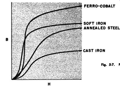
Fig. 5-7. Plot of B against H.
Permeability. Permeability may be understood from consideration of the effects which take place when the current is changed through a coil having a ferrous core. Changing the current changes the magnetizing force H, and the induction of the core (B) is measured for each value of the magnetizing force. Plotting B against H for common magnetic materials results in curves such as shown in Fig. 5-7. Note that most of the core materials represented in Fig. 5-7 exhibit an almost linear relationship between B and H for very low values of H. As H increases, B increases, first more rapidly, since lines of magnetization from the core material are added, and then less rapidly until a linear relation ship is re-established. In this final stage the core is said to be saturated, since the only increase in B is that due to increases in H. The core is completely magnetized in this state and can con tribute no additional lines of magnetization. Permeability or /A is defined as the ratio between B and H, and the use of this term permits the use of a new relationship: B=,J-1.
It can be seen from the curves that permeability is not a constant but varies with the magnetizing force. This is a distinguishing characteristic of core materials. It can also be seen that permeability is different for different materials, with ferro cobalt having very high permeability with a high induction at saturation. In most applications high permeability is required at high induction with low hysteresis.
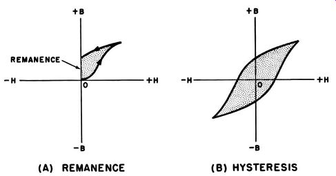
Fig. 5-8. (A) REMANENCE (B) HYSTERESIS
Hysteresis. When H is varied up to a maximum and then returned to 0, the value of B changes as shown (typically) in Fig. 5-8 (A). Note that B does not decrease at the same rate as its initial rise. Hysteresis is the term used to define the lag of B behind H. Examination of the curve shows that B is not equal to zero when H is returned to zero. This residual magnetism is known as the remanence of the core material. For B to be returned to zero, H must be applied in the opposite direction. The H necessary to accomplish this is known as the coercive force of the core material. The terms remanence and coercive force are only seldom used, since they arc indefinite characteristics which depend both upon the material and upon the values of H in use.
If ac is passed through the coil, the H-B relationship is (typically) as shown in Fig. 5-8 (B). Note that with a reversal of H, B also reverses in the same manner as described previously.
The closed curve shown is known as a hysteresis loop. It can be seen from the curve that the magnetization of the molecules within the core tends to lag behind the applied field and that a definite amount of force is required to reorient the magnetic lines in the opposite direction. The area within the hysteresis loop is a measure of the energy expended in rearranging the magnetic lines of the core material, and this energy appears as heat developed in the core. It is desirable that core materials have a hysteresis loop of minimum area.