AMAZON multi-meters discounts AMAZON oscilloscope discounts
INTRODUCTION
This section contains a survey of commercial inductors and transformers. The various basic commercial types will be reviewed according to their construction, fundamental applications, operating characteristics, and their outstanding physical and electrical features.
Most inductors and transformers may be classified according to certain features of construction which they share in common.
Most have laminated ferrous cores, powdered ferrous cores, or air cores. In addition there are only relatively few methods of coil winding which are suitable for mass-production manufacturing, and most commercial inductors and transformers are wound according to one, or a combination, of these methods. Much duplication will be avoided by reviewing the basic core and coil types before considering specific inductors and transformers. Therefore, this topic is presented first.
After this is a survey of commercial inductors and trans formers. Where applicable, these will be divided into power-line frequency, audio-frequency, and radio-frequency types, and the individual features of each of these will be considered separately.
CORES AND WINDINGS INDUCTOR AND TRANSFORMER CORES
Basic considerations. Commercial inductors and transformers can be divided into three main groups according to their use of core materials. It was mentioned in the previous section that the inductance of a coil can be increased by the use of magnetic core materials. When it is necessary to obtain maximum inductance in a minimum amount of space, ferrous cores are used whenever possible. These cores cannot be used at all frequencies, since the various losses and eddy currents increase with frequency. Eddy current losses are the most serious, since they increase as the square of the frequency. Hysteresis losses are kept to a minimum by using materials such as silicon steels and nickel-iron or nickel-iron-copper alloys, which offer a minimum resistance to a reversal in magnetic direction of the minute magnetic components within the material.
Eddy-current losses can be minimized by dividing the material into sheets as thin as several thousandths of an inch or into small particles. The sheets or particles are electrically insulated from each other, which limits the possible paths and the length of the possible paths through which the current can flow. Eddy-current losses also can be minimized by using materials which offer high resistance to the flow of electric currents.
In spite of the existing methods for minimizing the losses involved in the use of ferrous core materials, such losses strictly limit the frequency range over which these materials can be used.
Consequently, chokes and transformers designed to be used at frequencies below 20,000 hz may be constructed with magnetic core materials divided into thin layers. The layers used must be made increasingly thin as the frequency increases. The losses involved become increasingly significant above 5000 hz, and cores for use above this frequency are sometimes made of thin strips or ribbons of magnetic materials. At frequencies between 1000 and 5,000,000 hz or more, cores of compressed granular magnetic material are frequently used. At frequencies from about 0.5 to 5 mhz, air cores are commonly used, and at higher frequencies air cores are almost exclusively used.
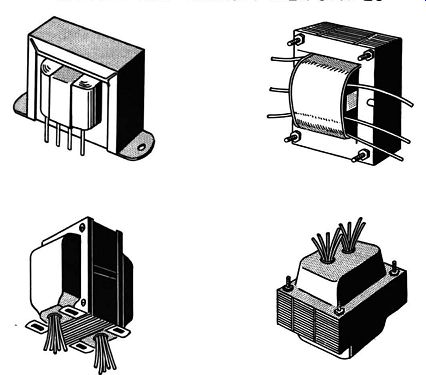
Fig. 6-1. Typical laminated iron-core inductor and transformer shapes. TYPICAL
LAMINATED IRON-CORE INDUCTOR AND TRANSFORMER SHAPES.
---------------
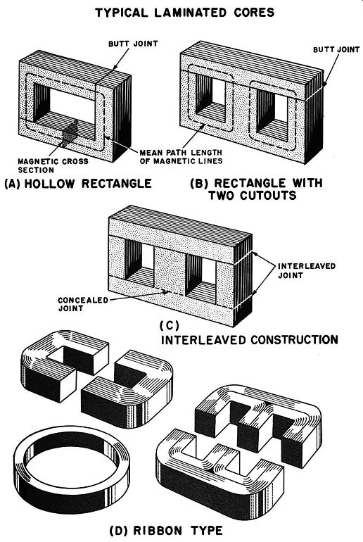
Fig. 6-2. Typical laminated cores. (A) Hollow rectangle. (B) Rectangle with
two cutouts. (C) Interleaved construction. (D) Typical ribbon cores.
TYPICAL LAMINATED CORES BUTT JOINT (A) HOLLOW RECTANGLE CONCEALED JOINT (B) RECTANGLE WITH TWO CUTOUTS INTERLEAVED JOINT (D) RIBBON TYPE
-------------
To summarize the effects of magnetic core materials, it can be stated that such cores provide three distinct advantages which are accompanied by three distinct limitations. The use of these cores may increase the inductance of a coil as much as two or three thousand times. This increase is generally automatically accompanied by an increase in Q, due to the definition of Q as outlined in the previous section. Since the magnetic lines necessarily follow the shape of the core, proper shaping of the core can result in confining the field so that it does not interfere with other circuits-thus cutting down on the amount of magnetic shielding required. Limitations of magnetic cores are that they saturate and thus restrict the gain in inductance, that they intro duce hysteresis and eddy-current losses, and that their permeability is not constant for all values of current.
Laminated cores. Laminated-core types of inductors and trans formers essentially consist of a core and one or more coils of wire, which are sometimes sealed in a container. Representative examples of unenclosed and encased inductors and transformers are shown in Fig. 6-1. This illustration shows the variety of trans former styles available from a single manufacturer. From outward appearances the only difference between chokes and transformers of this type is the number of leads or terminals appearing on the outside. Chokes almost always have only two leads or terminals which are unidentified by color or symbol. Transformers almost always have at least four or more leads or terminals, and these are always carefully identified by color or by stamped or engraved symbols or numbers.
Typical laminated cores are shown in Fig. 6-2. These cores consist of a number of layers of thin sheet metal formed in the shape of a hollow rectangle or, more frequently, in the shape of a rectangle with two rectangular cutouts. Note that each lamination consists of two parts. The reason for this is that it simplifies the manufacturing process to wind the coil or coils separately, then to fit it onto one section of the core. Then the remainder of the core is assembled around the coil. The path length of the magnetic lines through the core material and the cross section of the path may be estimated from the diagram shown in Fig. 6-2 (A). To reduce eddy-current losses, sheet metals used in inductor and transformer cores must be made thinner as the frequency of the expected current increases. At power-line-frequencies, lamination thicknesses are commonly in the range of 20 to 25 mils (thousandths of an inch). In the audio-frequency range, lamination thicknesses of 10 to 15 mils are commonly employed. At the upper end of the a-f band and for higher frequencies, the lamination thickness may range from 10 mils down to I mil. Since these sheets are never completely flat, and since they often are covered with various types of varnish or other materials for electrical insulation, the cross section of the magnetic material is not equal to the measured cross section of the stacked assembly. The percentage of magnetic material in the total cross section is called the stacking factor. For laminations of between 20 to 25 mils in thickness, the stacking factor is over 95%. For laminations of between 3 and 5 mils the stacking factor is between 70 and 80%. A small air gap exists at the point where the two sections of the laminations join together. This gap can vary from several thousandths of an inch down to several ten-thousandths of an inch across, depending upon the care with which the ends are squared and leveled. Since this space is actually an air gap in the path of the magnetic lines through the core, the inductance of the coil can be adjusted, if desired, by varying the size of the gap. When it is desired to take advantage of this effect, as in the swinging choke, to be considered shortly, a spacer of insulating material is inserted in the gap; selecting a spacer of the desired thickness provides a convenient means of gap adjustment. When it is desired to minimize air-gap effects, the interleaved construction, shown in Fig. 6-2 (C), may be used.
The operation of a swinging choke is based upon the fact that the magnetization of the core by dc in the coil can be reduced by increasing the air gap in the core. In a swinging choke the air gap is adjusted to give maximum inductance at a point between maximum and minimum de. Another method is to use a large gap in part of the core to provide the required inductance at maximum dc and a small air gap in another part of the core to provide about twice as much inductance for very small dc drain.
Powdered-iron cores. Since eddy currents increase as the square of the applied frequency, cores constructed of laminated ferrous materials become unsuitable for frequencies above the audio range.
To minimize eddy currents by causing further restrictions to the paths through which these currents can flow, the magnetic material is divided into small grains. The grains are mixed with insulating and binding materials and then are compressed at high pressure into the desired core shape.
Typical core shapes are shown in Fig. 6-3. This construction lowers eddy current and other core losses, and it lowers the permeability. Cores of this type permit high Q to be maintained at high frequencies. But in spite of the small size of the particles, eddy currents do still exist, and the particle size must be decreased as the frequency increases. For high audio-frequencies, particles as large as several thousandths of an inch are used, but for the vhf range particles must be as small as several millionths of an inch.
Coils employing powdered cores are generally wound in the same manner as for the air cores to be considered next. The use of the powdered core increases coil inductance by well over ten times. By employing mechanisms which permit adjusting the distance that a powdered core enters an air core, the inductance of the coil can be increased as desired. This is called permeability or variable-reluctance tuning.
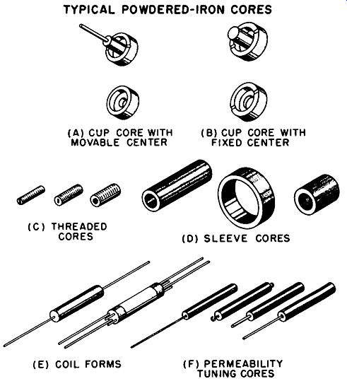
Fig. 6-3. Typical powdered-iron cores. (A) Cup core with movable center. (b)
Cup core with fixed center. (C) Threaded cores. (D) Sleeve cares. (E) Coil
forms. (F) Permeability tuning cores. TYPICAL POWDERED-IRON CORES (A) CUP CORE
WITH MOVABLE CENTER (C) THREADED CORES (E) COIL FORMS (B) CUP CORE WITH FIXED
CENTER (D) SLEEVE CORES (F) PERMEABILITY TUNING CORES
Air cores. In an air-core inductor the coil is wound upon a rod or tube of insulating material. A powdered core may be inserted part way into the tube-type core to obtain permeability tuning. There are many considerations which go into the selection of the insulating material, but most of these are resolved by the coil manufacturer. The material should be strong, moisture resistant, and heat resistant. It should have a low thermal co efficient of expansion, low core losses, and be easy to shape or form. All of the materials in use are treated to obtain the most desirable properties. Common materials in use include porcelain, polystyrene, ceramics, glass, and Bakelite. Treated Bakelite is the least expensive and most commonly used material for coil forms.
Polystyrene is frequently used in more expensive coil forms, since it introduces extremely low power-factor losses, and has a moisture resistance second only to glass.
INDUCTOR AND TRANSFORMER WINDINGS
A great many types of windings have been developed for use in inductors and transformers. Only a few of these are suitable for commercial production, and these will be described here. After a brief discussion of the types of wire used, there will be a survey of the types of windings used with air-core and powdered-core inductors and transformers. This will be followed by a review of the types of windings used with laminated cores.
Types of wire. Solid copper wire with enamel insulation is the type most commonly used in inductors and transformers. Litz wire, mentioned in Section 5, is most effective in the region between 500 khz and 5 mhz and has little advantage at other frequencies.
If a single-layer winding is used with an air space between turns, uninsulated wire may be used. This wire may be tinned to provide ease in soldering taps to the coil, or it may be silver plated to reduce skin effect at high frequencies.
Alternate types of insulation include single or double layers of cotton, silk, or nylon, which may also be used in combination with enamel-coated wire. After the winding is completed, it is usually impregnated with varnish or other insulation. This pre vents the absorption of moisture and provides some mechanical support to the winding.
Single-layer winding. The single-layer winding, shown in Fig. 6-4 (A), is the type most commonly used at frequencies from the top of the radio-broadcast band up to 200 mhz or more. If the winding is made so close that the insulation of the individual turns touch, the coil has high distributed capacitance along with considerable dielectric and eddy-current losses. Because of variations in wire diameter and tightness of the winding, inductance variations up to 10% can be expected.
To provide a means of adjusting for these variations, about 10% of the total number of turns are sometimes spaced away from the rest of the winding. Adjustment is made by sliding individual turns from one winding to the other or by sliding the entire group of end turns closer to or further away from the main winding. Another method is the permeability method of tuning by inserting a powdered-iron core mounted upon a screw thread, as shown in Fig. 6-4 (B). Moving the core into the coil increases the inductance. If the initial inductance of the coil is made slightly low, moving the core into the coil will bring it to the value desired. If the initial inductance is high, a copper or brass band mounted on a core of insulating material can be used to lower the inductance to the desired value.
If the turns are wound in a spiral groove in the coil form, or if a suitable cement is used to maintain the spacing, uninsulated wire may be used. This lowers the distributed capacitance and the other losses. Fixing the winding in this manner also stabilizes the inductance with regard to temperature.
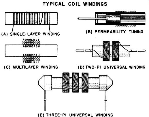
Fig. 6-4. Typical coil windings. (A) Single-layer (solenoid) winding. (B)
Permeability tuning. (C) Multilayer winding. (D) Two-pi universal winding.
(E) Three-pi universal winding.
Multilayer windings. When increased inductance is required without increasing the length of the coil, additional layers of turns can be wound upon the first layer. The simplest method of doing this would be to wind back and forth in the multilayer winding pattern shown in Fig. 6-4 (C). This type of winding has a high distributed capacitance, since wires with large potential differences are placed close and parallel to each other. While this effect can be tolerated at power- and audio-frequencies, the high distributed capacitance makes this type of winding unsuitable for rf.
Universal windings. The universal winding provides one method of adding more turns without obtaining the excessive distributed capacitance that is characteristic of multilayer windings. Universal windings are widely used in if and rf transformers and rf chokes. A universal coil is made by spiraling the wire back and forth during winding, and the result has an appearance similar to that shown in Fig. 6-4 (D). The crisscrossing of the wire holds the coil together without any supporting sidewalls. Distributed capacitance is low, since wires with large potential differences cross each other instead of being closely parallel.
When all the wire in the inductor is wound in a single coil of this type, the unit is known as a single-pi inductor. Distributed capacitance can be lowered even further by winding the wire into two or more sections, as shown in Fig. 6-4 (E). This is known as a two-, three-, or four-pi inductor, depending upon the number of sections used.
The inductance of a universal winding can be adjusted by the use of a powdered-iron core, as described previously. If a single-pi winding is loosely wound with only a few turns per layer, known as a honeycomb winding, the inductance can be increased by crushing the ends of the coil to decrease the overall length, while increasing the diameter. Or it can be decreased by crushing the circumference of the coil to decrease its diameter, while slightly increasing its length. If a multiple-pi winding is used, inductance can be increased or decreased respectively by squeezing the individual windings together or by spreading them apart. A single-pi universal winding can be made so that it is long with respect to the number of layers. The inductance of this type is most easily adjusted by permeability tuning.
The individual sections of a universal winding are manufactured in widths ranging from 1/16 to 1/2 inch. Inductance values range from several 1 ,henries up to more than 1 henry.
Windings for laminated cores. Figure 6-5 (A) shows the basic type of coil winding used with laminated-core inductors and transformers. A rectangular fiber or paperform provides the base for the winding. The form is sized so that it will slide over the core and provide sufficient clearance at the ends when the core is assembled. Solid copper wire coated with insulation is wound upon the form, leaving a small unwound space at each end to guarantee that the core will not cut into the wire. A layer of specially treated paper is sometimes used as insulation between each layer of turns. This prevents turns with a large voltage difference from coming too dose to each other-thus lowering distributed capacitance and permitting the use of only a thin layer of insulation on the wire itself. In addition, the use of paper insulating layers provides a mechanical gripping surface for the wire turns, and no special provisions are necessary to prevent the wire from slipping out of the open ends.
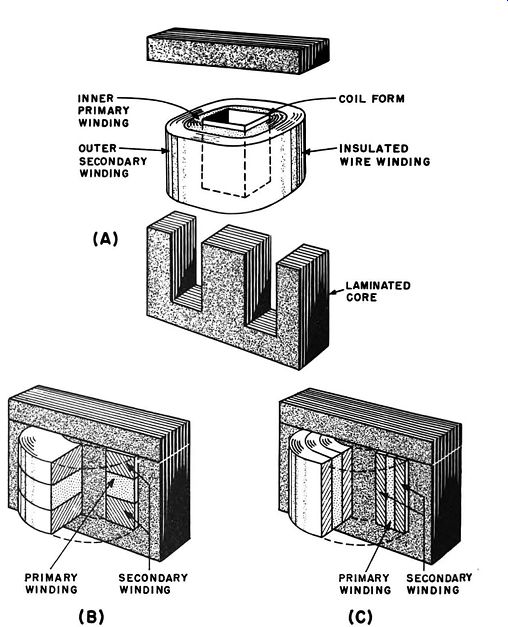
Fig. 6-5. Laminated core winding. (A) Coil on laminated core. (b) Side-by-tide
sectionalization. (C) layer-by-layer sectionalization.
If the paper insulating layers are omitted, the result is known as a random winding. The number of turns in the same space may be increased by about one and a half times; but superior insulating material must be coated on the wire, distributed capacitance is increased, and special holding devices must be used to prevent the turns from slipping off the ends of the form.
Either before or after assembly to the core, the coil assembly is vacuum impregnated with an insulating material which hardens after treatment. This provides additional mechanical support to the windings and prevents the absorption of moisture.
In laminated-core transformers the same basic techniques are used. The secondary winding or windings may be wound over the primary winding, with insulating layers used to separate the primary and the various secondary windings. There are special winding techniques which yield improved frequency response, balance between two identical secondary windings, and other special characteristics. These techniques include sectionalizing the primary and secondary windings either side by side or layer by layer, as shown in Fig. 6-5 (B) and (C) respectively.
A wide variety of combinations is possible. In addition, electrostatic screening may be used to prevent undesired signal pickup between the primary and the various secondary windings.
This electrostatic screening may be obtained by placing wire layers which will be close to ground potential at the dividing layer between the different windings. Another method is to use grounded layers of insulated copper between the various windings.
SHIELDING
The purpose of shielding is to prevent the electrostatic and electromagnetic fields generated by a coil from interacting with other coils and other circuit components. Containers of high conductivity metals are effective for both types of shielding. Electro static shielding is provided, since the container is connected to ground and shorts out stray electric fields. The conducting material in the container also generates eddy currents which oppose the magnetic field inducing those currents. Since eddy current increases with frequency, a given container provides better shielding as the frequency increases.
Aluminum shields are the most common. Copper shields are more effective due to their better conductivity, but they are more expensive. Shields of ferrous materials are sometimes used. Their usefulness stems from the fact that the stray magnetic field tends to concentrate within the magnetic material. Magnetic shields of this type are frequently supplemented by electrostatic shielding.
INDUCTORS
BASIC INDUCTOR TYPES
There are six basic types of applications for inductors in electronic equipment, and specific types of inductors are used for these purposes. Examples of typical circuits are shown in Fig. 6-6. Filter chokes are used in rectifier power supplies. In this application, the rectifier output is a d-c voltage which rises to a peak at a frequency usually equal to or twice that of the power line.
The filter choke exhibits high reactance to the ac component of the rectifier output, while it has a very low resistance for the d-c component. The ac component is bypassed to ground by means of one or more capacitors (usually electrolytic) as shown in Fig. 6-6 (A), and the current that passes through the choke has only a small percentage of a-c ripple. When a very small load current is drawn through the coil, the magnetic field generated by the coil is insufficient to magnetize the core. Thus, a given choke will have a much smaller filtering effect for very low load-current drain than for its full rated load. In most power supplies the inductance of the choke is selected to have the required reactance when the normal minimum load current flows through it. If this minimum is very low, a resistor may be added in parallel with the load to increase the current. In those applications where a wide variation in the load current is expected, a swinging choke is used, as shown in Fig. 6-6 (B). The reactance of such a choke varies with the dc load current through it so that the filtering effect is sufficient over the entire predicted current range. This type of choke is more economical for such applications than one which maintains essentially the same high inductance at large load currents as required for good filtering at small load currents.
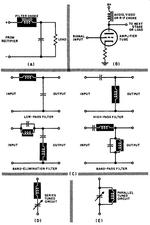
Fig. 6-6. Basic inductor circuits. (A) Filter circuit. (B) Plate-supply choke.
(C) Special filter circuits. (D) Series-tuned circuit. (E) Parallel-tuned circuit.
------------------------
TABLE 6-1
Commercial Inductors
Power-Supply 1:ilter Chokes and Swinging Chokes
Description: Encased or un-encased iron-core units. Style and mounting varies with manufacturer.
Range of ratings-filter chokes: ohms weight henries dc ma dc resistance size lbs.
20 15 900 1 ½x 1 ½ x 3in. ¾ 6 500 75 7½ x 6 x 7 in. 24
Range of ratings-swinging chokes: Description: Range of ratings: Description: Inductance range: Body size range: ohms weight henries d-c ma d-c resistance size lbs.
3-13 150-3 130 3¼ x2½x2½in. 2¼ 4-16 500-50 75 7½ x6x 7 in. 24
Audio Chokes
Similar in appearance to filter chokes. Ratings are generally at 200 hz.
ohms weight henries dc ma dc resistance size lbs.
130 5 6500 2¾ x2¾ x2¼ in. 1 ¾ 16 50 600 2x 3 x 1 ¾ in. 1 Video
Chokes Universal coils wound on plastic forms or on shunt resistors.
Powdered-iron-core types available.
1 to 500 µh
¾ in. long x 3/16 in. diam. to 3/8 in. long x 5/16 in. diam.
Rf Chokes Description: Single- or multiple-pi universal coils with or without powdered cores.
Inductance range: 0.2 µh at 1000 ma to 125 mh at 75 ma.
Many intermediate ratings. Average size 2 in. long x ½ in. diam.
------------------------------
Figure 6-6 (B) shows how audio-frequency, video-frequency, and radio-frequency chokes are used to connect d-c plate voltage to a tube across which a load is connected. In this example, the use of a choke permits almost full B+ voltage to be applied to the plate of the tube while providing high impedance to the signal voltage appearing at the plate. Although resistors are frequently used in such applications, a resistor causes a drop in the dc voltage applied to the plate, thus producing less favorable operating conditions for the vacuum tube in some cases.
Chokes are used in a wide variety of low-pass, high-pass, band elimination, and bandpass filters [see Fig. 6-6 (C)] to eliminate signals of certain frequencies while allowing those at other frequencies to pass through. Analyses of these types of circuits fill many pages in texts on the subject of electronic engineering. Inductors are also connected either in series or in parallel with capacitors, as shown in Fig. 6-6 (D) and (E) in order to form series- and parallel-resonant circuits. These are used in receivers, transmitters, and other more specialized equipment to permit amplification of only the particular frequency to which the circuit is tuned.
Commercial induction. Table 6-1 presents a survey of the out standing features of the inductor types which have been mentioned.
TRANSFORMERS COMMERCIAL TRANSFORMER TYPES
There are five basic uses for transformers in electronic equipment, and specific types of transformers are used for these purposes.
Each type has a number of variations which also will be considered.
Power transformers are used in electronic equipment to sup ply high-voltage ac to rectifiers and low-voltage ac to vacuum-tube filaments. In addition, they also supply alternating voltages for other specialized purposes. While power transformers generally are not equipped with a means for adjusting the voltage obtained from the secondary windings, certain special types which do provide for such variation will also be considered.
Audio transformers usually are used in conjunction with electronic audio amplifiers and provide a means for coupling various types of inputs and outputs to and from the amplifier.
In addition, they are used for other types of coupling, such as from line to loudspeaker in an intercom system. Five types of audio transformers will be reviewed.
Intermediate-frequency (i-f) and radio-frequency (r-f) trans formers are used in radio and television applications to provide a frequency-selective coupling between amplifier stages. I-f trans formers are adjustable in frequency, and they are almost always supplied as complete units together with tuning capacitors and shielding containers. R-f transformers are generally intended for use in tuned circuits which can be varied in frequency by the equipment operator. Because of this, the r-f transformer is generally supplied in the form of mounted coils, with or without a container, and the equipment manufacturer generally adds variable tuning capacitors and shielding as needed.
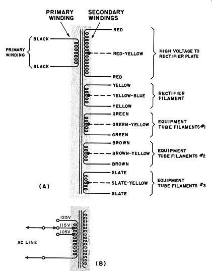
Fig. 6-7. Power transformers. (A) Color code for rectifier plate--and filament--supply
transformer. (b) Transformer with tapped primary. (C) VARIABLE
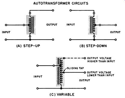
Fig. 6-8. Auto-transformers. (A) Step-up. (b) Step-down. (C) Variable.
(A) STEP-UP (B) STEP-DOWN
Pulse transformers are used in radar and other special applications. The input signal is generally a single half-cycle of square wave, the duration of which is frequently measured in u-Sec. The time interval between these input impulses may be measured in hundredths of a second or longer. The pulse transformer must step up or step down this signal as required by the application.
Because of the extremely short duration of the input signal, a pulse transformer must have a number of special features to make the output signal an acceptable duplicate of the input signal.
In addition, there is a wide variety of specialized transformers available for use in television and special-purpose equipment.
These types will be reviewed briefly without detailed consideration of the applications involved.
POWER TRANSFORMERS
Basic types. There are three basic types of power transformers in electronic equipment; schematic diagrams of these are shown in Figs. 6-7 and 6-8. Rectifier-plate and filament-supply transformers are the most common and have the most variations. The basic type is shown in Fig. 6-7 (A), along with the color code commonly used to identify the various leads. This type has a single primary winding and a number of secondary windings. Any of the secondary windings may or may not have a center tap, depending upon the requirements of the equipment in which it is used. Generally, one of the secondary windings steps up the power-line voltage for connection to the plates of a rectifier. When the rectifier is a vacuum tube, its filament is heated by a separate step-down winding. In addition, there is a step-down winding for heating the filaments of the various vacuum tubes in the equipment.
If it is necessary to isolate some of the vacuum-tube filaments from the others, separate step-down windings are used for the other filaments. Additional step-up or step-down windings also may be supplied as required for special purposes. Transformer manufacturers have available a wide variety of standard transformers of these types so that all usual requirements are met; additional special windings can be installed at extra cost.
The power-line voltage may be fairly stable, but it may vary from time to time. When the power-line voltage changes, the voltage outputs of all of the secondary windings also change, as determined by the turns ratios of the different windings. Certain types of equipment cannot operate properly if the secondary voltages are too high or too low by more than a small percentage.
While special voltage-regulating circuits are available to compensate for such changes, the transformer itself (when furnished with the appropriate taps) can be used to correct such conditions. In such an event the transformer primary may be equipped with a number of taps as shown in Fig. 6-7 (B), and a switch can be used to connect the line voltage to the desired tap. When the equipment is set up for use, the operator measures the line voltage; then he sets the switch to the marked position which is closest to that voltage. Since the switching changes the number of turns in the primary winding, the turns ratios of the various windings are thus adjusted to obtain the desired output voltages.
An autotransformer has a single winding. Part of the single winding is common to both the primary and the secondary. If the transformer is of the step-up type, the secondary uses more turns than the primary, and if it is of the step-down type, there are fewer turns in the secondary. Schematic diagrams of both these types are shown in Fig. 6-8 (A) and (B) respectively. The principles of operation are identical to those previously described for transformers. A step-up transformer often may be used in step-down applications, and vice versa, by interchanging the primary and secondary connections. The advantage of the auto transformer is that it is somewhat lower in cost than a transformer with separate windings, since it is easier to construct due to the fact that less wire and less winding time are required.
A distinct disadvantage of this construction is that it does not isolate the secondary winding from the power line, and this is unsuitable in many applications.
The autotransformer can be used to distinct advantage when a particular and precise output voltage is required. For such applications, one of the secondary taps may be manufactured in the form of a sliding contact which can be moved from the out side of the transformer case. A schematic of this type is shown in Fig. 6-8 (C). By moving the sliding contact, the operator can change the turns ratio and obtain any high or low voltage that is in the range of the transformer. Transformers of this type are generally connected between the power line and the primary winding of a rectifier plate and filament supply transformer, thus permitting more precise and convenient voltage adjustment than is available by taps on the primary winding of the latter transformer.
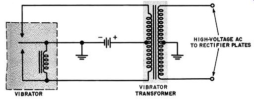
Fig. 6-9. Vibrator transformer hook-up.
This use is most common in laboratory setups, but variable auto transformers are sometimes installed in special equipment.
When high-voltage ac is required for a rectifier and the only available source of electric power is a low-voltage storage battery, a vibrator and vibrator transformer is sometimes used. A typical circuit is shown in Fig. 6-9, an arrangement common in auto mobile radios. The transformer is used only for supplying voltage to the rectifier, which is usually of the dry-metal type, and filament voltage for the vacuum tubes is obtained directly from the storage battery. In its operation the vibrator's moving con tact swings back and forth and changes the battery voltage (by interruption) to the form of an a-c voltage with approximately a square-wave shape. This voltage is stepped up by the transformer. The major difference between this and previous trans formers is that only one secondary winding is generally required, and a large turns ratio must be used to step up the 6- or 12-volt battery voltage to several hundred volts.
Commercial power transformers. Table 6-2 and the accompanying diagrams present the outstanding features of the power transformers which have been mentioned.
-----------------
TABLE 6-2 Power-Supply Transformers
Combination Rectifier Plate and Filament Supply
-----------------------
AUDIO TRANSFORMERS
Basic types. There are five basic types of audio transformers in general use. Schematic diagrams of typical applications and color codes are shown in Fig. 6-10. All of these applications make use of the impedance-matching abilities of transformers. When a low-impedance phonograph pickup or microphone must be connected to the input grid of an amplifier, an input transformer is used as shown in Fig. 6-10 (A). R-C coupling is widely used to couple the plate of an amplifier tube to the grid of the following stage, however, transformers are sometimes used for this purpose, as shown in Fig. 6-10 (B). Another useful application for interstage transformers is to connect the plate of an amplifier tube to push-pull amplifier grids in the following stage, as shown in Fig. 6-10 (C). If the grid or grids in the following stage or stages draw current, as in the case of a final audio-output stage, the transformer is known as a driver transformer. When the transformer couples the plate or plates of the final amplifier stage to a loudspeaker, as shown in Fig. 6-10 (C), it is commonly called an output transformer. In those cases in which an output transformer must be capable of matching a wide variety of speakers to a wide variety of final amplifier stages, a universal matching transformer (see Fig. 6-10D) is used. If the transformer is used to couple the final stage of an audio amplifier to one of the r-f amplifier stages of a transmitter, as shown in Fig. 6-10 (E), it is known as a modulation transformer.
Impedance effects. Impedance effects present serious limitations to transformer coupling unless special corrective measures are taken. The reason for this is that the inductive reactance of the primary and secondary windings increases with frequency. To illustrate this very quickly, consider only the inductive reactance of the primary winding. This reactance is equal to 2 pi f L. Thus at frequencies of 100 and 1000 hz, the X 1 , of the primary winding is 10 times and 100 times higher respectively, than it is at 10 hz.
This X 1, in many applications appears as the plate-load impedance of the tube to which the primary winding is connected. As a result, unequal amplification takes place throughout the a-f range. As an example, the overall gain produced by an uncorrected trans former-coupled amplifier is about 2.5 times higher at 200 hz than at 10 hz. At about 3000 hz the gain is about 3 times higher than at 10 hz. At higher frequencies, capacitance effects become significant, and the gain drops very rapidly.
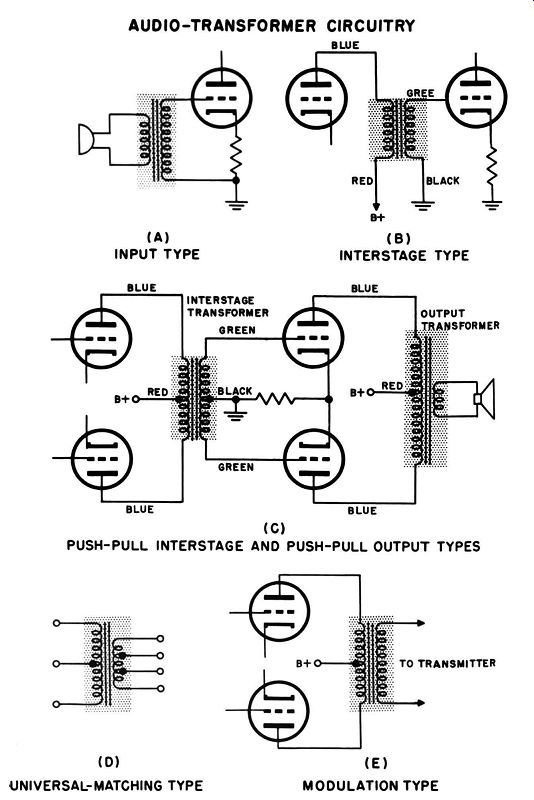
Fig. 6-10. Audio transformer. (A) Input. (b) interstage. (C) Push-pull Interstage
and push-pull output. (D) Universal Matching. (E) Modulation.
Transformer impedance matching. Impedance matching is a transformer function which finds widespread applications which have already been mentioned. In these uses the principles involved are always the same and are best illustrated by considering the impedance-matching characteristics of an output transformer. As was shown in Fig. 6-10 (C), an output transformer matches the high-impedance plate circuit of the final amplifier stage (several thousand ohms or a great deal more) to the low-impedance voice coil (from 2 to 16 ohms) of the speaker.
When there is no load connected across the secondary winding, there is no effect, or essentially no effect, on a load connected across the voltage source connected to the primary. If a load of resistance R. is connected across the secondary, the load resistance R, that is effectively applied to the primary is indicated by the relationship:
~=(5-)2 R, N, ' where N, and N, represent the number of turns in the primary and secondary windings respectively. Thus the load matching characteristic of a transformer is determined by the turns ratio of the windings.
If the turns ratio is selected according to the above relation ship, the voltage appearing across the primary and secondary windings is as follows:
.!!!._= (~ )2 R. V, '
… where J'P and J', are primary and secondary voltages, respectively.
The problem of manufacturing impedance-matching trans formers for electronic equipment is not an insurmountable one, since there are a limited number of applications in which this technique is used and there is a high degree of standardization in primary and secondary loads. Thus, almost all impedance matching problems encountered in practice can be resolved by a rather limited number of such transformers.
Unusual cases can be solved frequently by the use of so-called universal-matching transformers. These have a secondary winding with a number of taps, and sometimes the primary winding has a center tap, as shown in Fig. 6-10 (D). The transformer input can be connected across either the entire primary winding or across half of the primary winding. The transformer load can be connected across any two of the connections to the secondary winding. Consequently, a number of turns ratios are available from a single transformer. It is the number of turns actually connected in the primary and secondary circuits that determines the ratio, and the number of unconnected turns is not involved.
All of these various types of audio transformers are available as cased or uncased units. Appearance and mounting types vary with the manufacturer. Midget types are available which easily fit within a 1-inch cube and weigh less than ½ ounce. Universal output transformers are available to supply 75 watts to a speaker voice coil. These transformers measure about 5 by 4 by 4 inches and weigh about 8 pounds. Even larger output transformers are available for use with high-fidelity equipment.
Transformers for transmission line. The audio transformers mentioned in the previous paragraphs are generally used under conditions in which the two components to be coupled together by the transformer are located no more than a few feet apart.
In sound studios, theaters, intercom systems, and large hi-fi installations the use of the equipment often requires that micro phones, record player pickups, amplifiers, and speakers be located tens, or even hundreds, of feet apart. If a high-impedance micro phone or record player pickup is separated from its amplifier by such distances, there may be excessive noise pickup from surrounding power lines and other equipment.
Connecting low-impedance devices, such as the secondary of an output transformer to a speaker voice coil, over such distances may result in sound power loss when the resistance of the connecting wire reaches a significant fraction of the voice coil impedance. Transmission-line arrangements are used to make such couplings with maximum efficiency. The choice of components for these arrangements depends upon the impedances of the devices to be connected, and the signal level involved.
The distant devices are connected together by means of line transformers and transmission lines. Characteristic impedances of a-f transmission lines in common use are 30, 50, 250, 500, 1000, 1500, and 2000 ohms. A wide variety of line transformers, such as microphone-to-line, line-to-grid, plate-to-line, line-to-speaker, etc., are used, as appropriate to the devices to be connected. The specifications for such transformers include a statement of the impedances of the device and transmission line for which they are intended.
Commercial audio transformers. The various types of audio transformers mentioned previously are available as cased or un- cased units. Appearances and mountings vary. The size and weight range from subminiature input types, which measure about 1/8 by 1/8 by ¾ inches and weigh about 0.02 pound to standard universal output types measuring about 5 by 4 by 4 inches and weighing about 8 pounds. Even larger output transformers are available for use with high-fidelity sound equipment or amateur radio applications. Because of the many variations, a survey of these trans formers does not lend itself to a simple listing. Instead, the paragraphs which follow present a descriptive review which includes the most outstanding characteristics and functional variations.
Input transformers have turns ratios ranging from approximately 1 to 10 through approximately 1 to 100. These are usually used for low-impedance devices such as speaker-type microphones, carbon microphones, and low-impedance dynamic microphones or pickups. Typical primary impedances are 4, 8, 15, 30, 50, 125, 200, 250 and 500 ohms, with and without center taps. Typical secondary impedances for line input include 50, 125, 200, 250, 300 and 500 ohms. For input to grids the secondary impedances range from about 50,000 ohms to about 1.5 megohms. Many input transformers have multiple primary and secondary taps to make them useful for a wide variety of impedance conditions. Input transformers are most commonly divided into the microphone to-line, line-to-input-line, microphone-to-grid, pickup-to-grid, and line-to-grid types.
Interstage transformers have turns ratios generally ranging from 1 to 1 through 1 to 4. Primary impedances commonly range from 5000 to 20,000 ohms and secondary impedances from 10,000 to 200,000 ohms. Some types are available with center taps in either or both windings. Multiple-purpose types have center tapped primaries and split secondary windings permitting a variety of step-up or step-down connections for single-ended or push-pull stages. Interstage transformers are generally of the single plate to-single grid, single plate-to-push-pull grid, push-pull plate-to single or push-pull grid, and push-pull plate-to-parallel grid types.
Driver transformers are interstage transformers used in high power audio amplifiers, usually between the final and next-to-final stages. These are generally of the single plate-to-push-pull and/or push-pull plate-to-push-pull grid types. The secondary windings generally are designed to carry more current than ordinary inter stage transformers. There is a type for 500-ohm line to push-pull grids, and this has a center-tapped primary. Turns ratios range from 1 to 0.75 through 5 to 1. The maximum current ratings range from 5 to 150 ma per section.
Modulation transformers are commonly divided into two groups. The plate modulation type has a center-tapped primary with impedances ranging from 5000 to 15,000 ohms and secondary impedances ranging from about 3000 to 10,000 ohms. Power ratings extend from 2.5 to 250 watts or more. The multiple-match type has tapped primary and secondary windings so that impedances of from 2000 (or less) to 20,000 ohms (or more) can be obtained in either winding. Power ratings extend from 10 to 500 watts or more.
Output transformers are of the single plate-to-voice coil, push pull plate-to-voice coil, single and push-pull plate-to-line, line-to voice coil, universal, hum-reducing, ultra-linear and crystal-cutter types. Primary impedances generally range from about 1500 to 30,000 ohms. (Primary impedances of the line-to-voice coil types are of the order of 250 or 500 ohms.) The most common secondary impedances for voice coil use are 2, 3.5, 4, 6, 8, 15, and 16 ohms.
Power ratings extend from about 2 to 100 watts.
R-F AND I-F TRANSFORMERS AND INDUCTORS
Radio-frequency (r-f) and intermediate frequency (i-f) trans formers are used to couple the various r-f and i-f stages of radio and television receivers (and transmitters). In both these types of transformers, either the primary or secondary or both windings are tuned to a particular frequency, usually by connecting a capacitor across them. In some cases the winding is tuned by its own distributed capacitance or the input capacitance of the associated tube stage.
Tuned transformers are used for this purpose because receivers are intended to amplify only a very limited band of frequencies or-in a radio transmitter-only one frequency at a particular time.
Using a capacitor to form a parallel-resonant circuit with one or both windings causes a high impedance to be presented only to signals at or close to the resonant frequency. Signals at other frequencies "see" only a low impedance and are effectively shorted out.
Both r-f and i-f transformers are very similar in construction and operation. The major difference is that r-f transformers are usually used in conjunction with at least one variable capacitor or variable inductor so that they can be tuned to the desired frequency by the equipment operator. On the other hand, i-f transformers are always tuned to the same frequency. Therefore, these are supplied with adjustable capacitors or inductors which are set by the equipment manufacturer (or service technician) and require no adjustment by the equipment operator.
There are literally dozens of types of special transformers and inductors available for use in broadcast-band radio, communications receivers, f-m radio, and television, plus industrial and military electronics. The major features of all of these various types will be brought to light by a consideration of typical r-f and i-f transformers and oscillator coils used in broadcast-band receivers. The other coils and transformers mentioned have basically the same features and differ mainly in the frequency of operation and in the addition of extra windings. Manufacturers' condensed descriptions of these coils and transformers generally list only the specific characteristics that are important in the use of each part. It is common to find some, but not all, of the following characteristics listed: size, case style, weight, turns ratio, primary and secondary resistance and impedance, Q, voltage and current ratings, and special features.
Capacitance-tuned r-f transformers. The general construction of the most commonly used types of broadcast-band r-f transformers, and typical circuits, are shown in Fig. 6-11. The coils are generally wound upon forms of treated compressed paper or Bakelite, al though polystyrene is often used in more expensive equipment designed to operate at higher frequencies. Adjustable powdered iron core inserts are frequently mounted in the coil form to provide a convenient means for adjusting the coil inductance.
In broadcast-band transformers, universal and honeycomb windings are widely used to obtain the required inductance with minimum distributed capacitance. At higher frequencies, which require less inductance, the same effect can be obtained with single layer windings. The coupling between the coils may be fixed by the transformer manufacturer, as shown in 6-11 (A), for best operation in standardized circuits. It is fairly common for the equipment manufacturer to order r-f transformers manufactured to particular specifications for best operation in specially designed circuits.
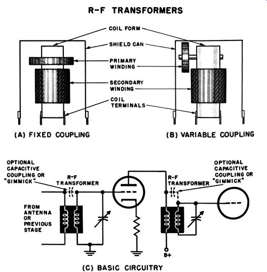
Fig. 6-11. R-f transformer. (A) fixed coupling. (b) One type of variable coupling
(C) basic circuits. R-F TRANSFORMERS ; (A) FIXED COUPLING (B) VARIABLE COUPLING
(C) BASIC CIRCUITRY
Standard r-f transformers are also available with a construction which permits the coupling between the primary and secondary windings to be adjusted as required by the equipment builder.
This may be accomplished by mounting the primary winding on a circular collar which can be moved along the length of the coil form, or, as shown in Fig. 6-11 (B), by mounting the primary so that it can be moved along an insulating rod mounted at right angles to the secondary coil form. Frequently the rod angle is adjustable. R-F transformers are available with or without shield cans. The use of shield cans depends upon the proximity of other circuits in the equipment layout.
Figure 6-11 (C) shows a common circuit arrangement for using an r-f transformer to couple an antenna to an r-f amplifier tube and a circuit for coupling two r-f amplifier tubes. Note that it is common for only one of the transformer windings, usually the secondary, to be tuned by means of a variable capacitor. Although increased gain may be obtained by using ganged capacitors to tune both windings simultaneously, this extra gain is generally considered insufficient to justify the increased cost and space requirements of the added capacitor.
Gain is more economically obtainable by means of i-f amplifiers generally included later in the same equipment. The most usual arrangement is to use a high-impedance primary winding without a variable capacitor. The stray capacitance in the primary circuit, and sometimes an added fixed capacitor, is used to resonate this winding at approximately 0.7 times the lowest frequency to be amplified.
The result of tuning the primary winding in this manner is that the overall transformer gain at the low-frequency end of the tuning range is higher than at the high-frequency end. Gain at the upper frequencies can be increased by using capacitive coupling between the windings, as shown by the dotted capacitor in Fig. 6-10 (C). Although a small capacitor can be used for this purpose, it is more convenient to connect a piece of wire to the primary and to twist it in one or more turns around the insulated secondary winding. This device is called a "capacitive winding" or, more popularly, a "gimmick," and it adds from 1 to 10 µ.µ.f of coupling between the two windings.
The most common type of r-f transformer for use in broadcast band equipment can be tuned from 500 to 1700 khz when connected to a variable air capacitor with an approximate range of 15 to 400 µ.µ.f.
Inductance-tuned r-f transformers. In the interests of space saving and economy of manufacture, special r-f transformers are made with a powdered-iron insert which can be moved freely inside the coil form to accomplish variable permeability tuning.
The iron core is connected to the receiver tuning knob (or adjustment screw) by a special mechanism which varies the position of the core inside the coil form as the knob (or screw) is turned.
The position to which the core is set by the tuning knob adjusts the inductance of the coil so as to resonate it at the desired frequency with a fixed capacitor connected across the ends of the coil.
Either or both coils of the transformer may be tuned in this manner. Except for the method of tuning, the principles involved are the same as for capacity-tuned r-f transformers. Inductance-tuned transformers are generally made to order for equipment manufacturers, and, to date, there is no large selection of standardized types available, as is the case with capacity-tuned types.
Oscillator coils. All superheterodyne receivers contain an oscillator stage. Of the many oscillators which can be used, there are only two basic types of oscillator coils which meet the requirements of most types of superheterodyne oscillator circuits. The general appearance and construction of an oscillator coil unit is almost identical to that of the capacitance-tuned r-f transformers which have been described. Some oscillator coil units have two universal windings, and these are used in conjunction with penta grid converter oscillator circuits. Another type has a single winding with a tap. Most broadcast oscillator units are designed for use in conjunction with variable air capacitors with a maximum capacitance of 365 µ.µ.f. With such a capacitor they can be tuned over a range of from 540 to 1600 khz.
I-f transformer. I-f transformers are constructed in very much the same manner as r-f transformers. However, the i-f transformer is always tuned to the same frequency, and no adjustment is required by the equipment operator. This means that ganged variable capacitors are unnecessary for tuning, and both windings can be set to the desired frequency either by adjustable air or mica capacitors or by means of fixed capacitors and adjustable powdered-iron inserts in the coil form. Both of these tuning methods are economical and are in widespread use. Construction details of one of the types employing adjustable air capacitors are shown in Fig. 6-12 (A). Although adjustable air capacitors are commonly used in more expensive units, compression-type mica capacitors are used in lower-cost units. Ceramic trimmers, with or without supplementary temperature compensation, are used in special-purpose units.
When permeability tuning is employed, the construction is generally the same. The variable capacitors are omitted, and fixed mica or ceramic capacitors are used instead. The upper coil is tuned by an adjustable powdered-iron core which is set to the desired position by means of a screw adjustment at the top of the coil form, while the lower coil is adjusted by means of a similar arrangement at the bottom. A typical unit of this type is shown in Fig. 6-12 (B).
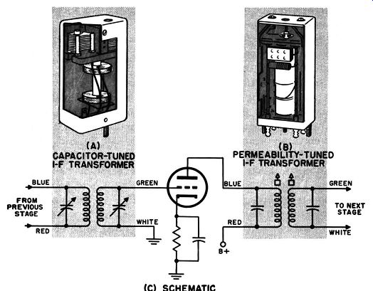
Fig. 6-12. I-f transformers. (A) Capacitor tuned. (b) Permeability tuned.
(c) basic circuits.
Figure 6-12 (C) shows a typical schematic with color coding.
For illustrative purposes. the first i-f transformer is shown as capacitor tuned and the second i-f transformer is illustrated as permeability tuned.
In broadcast-band equipment, i-f transformers usually are dc signed for tuning to a frequency of 455 khz. Frequencies commonly used in i-f circuits of television and communications receivers are 4.5, 10.7, 21, 30 and 41 mhz.
OTHER TRANSFORMER TYPES
Extensive developments in television and military and industrial electronics have led to the development of a large variety of special-purpose transformers and inductors. To make a comprehensive review of the function and special characteristics of these units would require including extensive information which is beyond the scope of this guide. However, to give the reader at least a summary of the most outstanding types, the paragraphs which follow review the most important electrical specifications or the most widely used types.
Television deflection yokes contain coils for the horizontal and vertical deflection or the picture-tube electron beam. Each coil is divided into two halves for location on opposite sides of the picture-tube neck, and all four coil sections are mounted in a single unit which fits around this neck. Horizontal coil ratings range from about 8 mh, 13 ohms to 30 mh, 45 ohms; vertical coil ratings range from about 3.5 mh, 3.5 ohms to 50 mh, 65 ohms.
Typical maximum scan angles include, 50, 54, 70, 90, and 110°. Television filter chokes are intended for use in high-voltage power supplies. Their insulation ratings range from 500 to 3000 volts rms. Typical inductance ratings are about 3 henries at 50 ma (200 ohms resistance), 1 henry at 300 ma (43 ohms resistance), and 10 henries at 100 ma (225 ohms resistance). Inductance values are also listed for various percentages of the rated value of current, such as 75% and 115% off the rated ac in ma.
Television focus coils are designed for mounting in the desired position around the neck of the picture tube. DC resistances range from about 200 to 1000 ohms, current ratings from about 75 to 200 ma.
Television high-voltage oscillator coils are intended for systems using separate high-voltage power supplies. The coil ratings extend from about 8000 volts at 350 µ.a to about 30,000 volts at 50 µ.a.
Television width coil specifications list the inductance range and resistance of each coil. Typical inductance ranges extend from 0.05 to 0.50 mh up through 1 to 10 mh. Typical resistances are 0.5 to 30 ohms. Width coils are available with automatic gain control windings of typically 2.7-7.6 mh, 19.5 ohms, or 0.16-70 mh, 1 ohm. Some types can be used as either width or linearity coils.
Linearity coil specifications also list the inductance range of the coil, which is generally in the same order of magnitude as for width coils. Linearity coils are also available with tapped windings.
Television horizontal output transformers are commonly known as "flybacks." Their ratings range for conditions such as 50° scan with 10,500-volt second anode, 320-volt B+, 420-volt boost; and 110-deg scan, 21,000-volt anode, 300-rnlt B+, and 480-volt boost.
Television vertical blocking-oscillator transformers are avail able in a variety of mounting styles and with a range of turns ratios from about 1 to 0.5 through 1 to 4.2. Horizontal blocking oscillator transformers typically have a turns ratio of 2 to 1 and are usually available in either open construction or in completely enclosing cases.
Television vertical deflection output transformers most frequently have turns ratios in the range of from 6 to 1 through 70 to 1. The primary impedances range from about 3000 ohms at 40 ma dc to about 30,000 ohms at 10 ma dc.
Television booster and converter transformers are usually in tended for use with a plate supply rated for 120- or 150-volts ac and a d-c current of either 25 or 50 ma. The filament supply is generally 6.3 volts at from 0.5 to 1.5 amperes.
Photoflash transformers have been developed for use with photographic "strobe" lights. Their weight is generally less than 2 pounds and sometimes as low as 0.2 pound. Different models are available for different input power sources, such as: 4- or 6-volt dc vibrator, 117 volts ac, or discharge from a charged capacitor. The output windings are intended for use in dc circuits of about 450 to 2200 volts.
Transistor transformers are intended for use with transistors in miniature and subminiature equipment. These transformers have primary and secondary winding arrangements similar to those used for equivalent vacuum-tube circuits. Some transistor audio transformers will fit inside a ½-inch cube and others will fit into a ¾-inch cube. Types intended for r-f and i-f amplifiers generally measure ½ by 1/2 by ¾ inches or smaller. Due to the characteristics of transistors, the primary and secondary impedances of the associated transformers often differ from those found in equivalent vacuum-tube circuits, for example, transistor-to-speaker transformers where typical primary impedances are 25, 50, 200, 250, and 500 ohms.
Pulse transformers and inductors, used in radar and industrial equipment, operate in conjunction with pulses ranging from about 0.10 to 100.0 µsec in duration at repetition rates from about 500 to 500,000 pps (pulses per second). The peak power handled in these circuits may be as low as millionths of a watt or higher than 10 million watts. The types of circuits used in conjunction with pulse signals are even more extensive than those found in television equipment. Because of the wide range of conditions under which pulse transformers and inductors are used, there are many basic types and many variations. Sizes range from as small as a cigarette filter to larger than heavy-duty power transformers in large TV sets.
PIINTID CIRCUITS AND COMPONENTS
A discussion of "printed" resistors, capacitors, and inductors has been reserved until this time because these units are most frequently combined, together with their associated wiring, in a single compact unit.
Printed circuit. The purpose of printed and etched circuits is to achieve complete equipment units or sections of minimum size. The most common type of "printed" circuit is actually an etched circuit. It consists of a sheet of insulating material to which a thin sheet of copper is bonded. A network of acid-resisting material is deposited over the copper by silk screening, printing or photographic techniques. An acid bath is used to etch away the unprotected copper.
The remaining copper is in the form of thin bands which duplicate the function of the wires which interconnect the components on a standard circuit board. Soldering terminals, and often tube socket terminals, are etched into the copper and have holes drilled completely through them and through the board.
This permits standard circuit components and subminiature tubes or transistors to be soldered directly to the board. Truly "printed" circuits have the same form, but the copper bands are replaced with a silver-bearing, highly conductive ink which is printed or silk screened directly onto the insulating board. An etched board with mounted components is shown in Fig. 6-13.
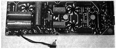
Fig. 6-13. Etched board with assembled components.
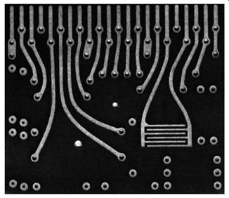
Fig. 6-14. Plug-in circuit with printed capacitor.
Printed components. Although standard or miniature resistors, capacitors, and inductors arc generally used in conjunction with printed circuits, these components are often printed directly onto the board.
Resistors are made by printing, silk screening or stenciling a straight or "zigzag" line of conductive ink between two printed terminals. The total resistance of this printed unit is determined by the length, width, and thickness of the ink line and by the conductivity of the dried ink. The ink consists of minute metal particles mixed with an insulating binder and a solvent. Once the solvent dries, the conductivity of the ink is determined by the proportions of metal and binder. It can be seen that there are four factors which affect the final total resistance and that a high degree of precise control is necessary in order to obtain the desired value. Because of the special techniques involved, few equipment manufacturers attempt to make their own printed resistors. An equipment manufacturer wishing to make use of printed resistors can order the modular units, to be considered later, or he can order to his specifications a printed circuit board from a company specializing in such services.
Coupling capacitors can be made by printing or etching techniques. Capacitors made in this manner are similar in construction to fixed air capacitors. Two parallel lines of conductive material are formed close to each other (see Fig. 6-14). The capacitance obtained depends upon the length, thickness, and width of the lines, the distance between the lines, and the dielectric constant of the combined insulation and air between them. Higher values of capacitance can be made by printing a number of parallel lines and interconnecting them to simulate the construction of a multiple-plate fixed air capacitor. Printed capacitors can also be made by forming large flat areas of conductive material on opposite faces of the insulating board.
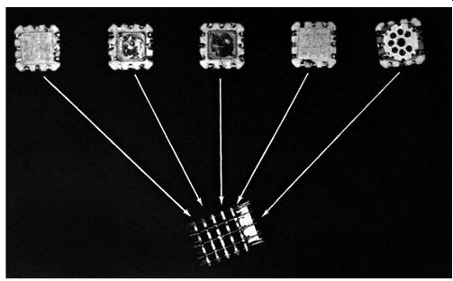
Fig. 6-15. Component ports of a module. Wafers contain tube socket, capacitors
and resistors.
Rf coils can be constructed by printing or etching techniques.
Since even a straight line of conductive material has inductance, it is possible to increase the inductance by forming a number of parallel lines and connecting the ends to form a long zigzag path.
Additional increase in total inductance can be obtained by dc creasing the spacing between the lines. It is possible to make rf transformers by meshing together two such constructions.
As in the case of printed resistors, the manufacture of printed capacitors and inductors requires a high degree of precision. The usual alternatives for the equipment manufacturer are to order standard modular units or to have printed circuit units manufactured according to his specifications.
Modular units. Modular units are constructions which contain combinations of the printed and etched components considered previously. Standard miniature resistors, capacitors, and inductors are sometimes also combined into the construction. The complete unit is encased in a jacket of insulating material, and the connecting leads or terminals protrude from the jacket. Sometimes the modular units are made in the form of flat rectangles which can be fastened together with other similar units in a "Tinkertoy" construction (see Fig. 6-15). Such assemblies can be used to make up one or more equipment stages, including sockets for miniature tubes or built-in transistors. Typical standard modular constructions that are available include cathode followers, video limiters, dc regulators, dual cathode limiters, video amplifiers, etc.
There are relatively few complete standard modular units of the type mentioned. On the other hand, there are many basic single-package units consisting of one or more printed resistors and capacitors together with interconnections. These units when connected to a vacuum tube (or transistor) make up a complete or almost complete equipment stage. Typical stages constructed in this manner include pentode amplifiers, vertical integrators, output stages, pentode detectors, horizontal oscillators, filters, interstage coupling networks, and a wide variety of special circuit components. Sizes of these single-package units range from ½ x ¼ x 1/8 inch for a simple resistor and capacitor network to 1 ½ x 1 x 3/16 inch for a complete vertical integrator network containing eight interconnected resistors and capacitors.