Television antennas are really quite easy to install. They are made so by most manufacturers of tv antennas, and it is especially true of the Archer line, sold exclusively by Radio Shack.
When you buy an antenna, the package you get is much smaller than the antenna. This is because the long elements on the antenna are folded flat against the boom, like the wings of a bird folded against its body. Fig. 7-1 shows an Archer antenna being pulled out of its box. Its elements are folded to make a compact box fit. In Fig. 7-2 the antenna is being pre pared for installation. Two pairs of elements have been un folded; the other pair is still folded. No tools are needed to ready the antenna for installation. The elements are unfolded by hand. Specially designed swivel joints snap the elements into place when they are opened. In fact, it is impossible to re fold the elements without damaging them, that's how securely they are held in place. When completely unfolded the antenna looks like Fig. 3-4 in Section 3. The elements of the uhf front section are so short they do not need folding, so are fixed in place.
Very complete instructions are supplied for unfolding and installation. While complete, the language is compact and terse, as seen in Fig. 7-3, which shows a copy of the instructions supplied with the antenna mentioned above. Also included with Archer vhf/fm/uhf antennas is a vhf/uhf splitter, the use of which will be covered later.
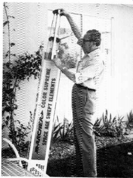
Fig. 7-1. Packaged antenna.
ROOF MOUNTING
The most popular place to mount a tv antenna is on the roof of your home. If you are located close to a tv station, and your house is orientated correctly, the antenna may be mounted in the attic. In deep fringe areas even the roof level of the house may not be high enough, and a high tower or mast is needed.
But for average metropolitan and suburban distances, the roof of a home usually provides a good height for the antenna.
In addition to the antenna and a mount, you will need a metal mast, either five feet or ten feet long. These are standard tv items in all stores selling tv antennas.
There is a large variety of hardware items available for mounting an antenna on the roof. One of the sturdiest is the tripod type of mount shown in Fig. 7-4. It is fastened to the peak of the roof as shown in the inset sketch, or onto a flat ...
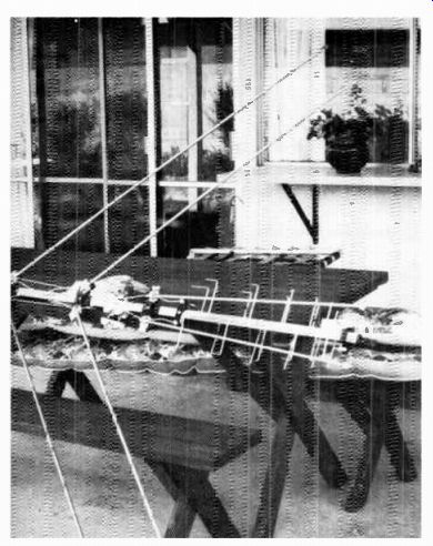
Fig. 7-2. Unfolding the antenna elements.
... roof. Normally a five-foot mast is fastened to the antenna, and the assembly is inserted through the apex of the tripod and through the center brace, for a two-point hold onto the mast.
When purchased, the tripod is in a long, but narrow box, as the center brace folds for easier packaging. The bottom feet are adjustable for slanting to match the roof lines. For greater height, a 10-foot mast may be used in this mount.
The roof mount of Fig. 7-5 has hinged base plates for adjusting to the roof slant. It is built of heavy-gauge material and will support a tv antenna on a 5-ft mast without additional guying. If a 10-ft mast is used, guy wires should be run from about the middle of the mast to guy screw eyes or hooks in the roof.
Both of the above roof mounts are fastened to the roof with long wood or lag screws. The screws must be long enough to go through the shingles, or tar paper, whichever is used, and into the wood below. If possible, find the location of the roof rafters ...
-----------------
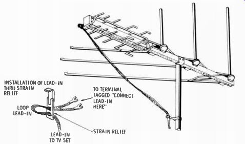
Fig. 7-3. Instructions for installing a tv antenna, under the wood sheathing
beneath the shingles; long screws make a more secure hold when they also
grip the roof rafters.
INSTALLATION OF LEAD-IN THRU STRAIN TO TERMINAL RELIEF TAGGED "CONNECT LEAD-IN LOOP HERE" LEAD-IN LEAD-IN TO IV SET STRAIN RELIEF
1. UNFOLD THE ELEMENTS OF THE ANTENNA AND ATTACH THE ANTENNA TO THE TOP OF THE MAST.
2. AIM THE ANTENNA TOWARD THE DESIRED STATION OR IF A ROTOR IS TO BE USED, FOLLOW THE DIRECTIONS LISTED WITH THE ROTOR. TIGHTEN THE MAST CLAMP.
3. ATTACH THE 300-ohm TWIN-LEAD WIRE TO THE TERMINAL POINTS TAGGED "CONNECT LEAD-IN HERE." IF YOU ARE USING YOUR OLD LEAD-IN WIRE, BE SURE THE INSULATION IS NOT CRACKED OR WEATHERED SO THAT ELECTRICAL BREAKDOWN CAN'T OCCUR. IT IS RECOMMENDED THAT NEW LEAD-IN BE USED WITH ANY NEW ANTENNA INSTALLATION. LEAD-IN SHOULD BE TWISTED APPROXIMATELY THREE TURNS EVERY 5 FEET.
4. USE SUFFICIENT STANDOFFS ON LEAD-IN TO PREVENT WHIPPING IN THE WIND. STAND-OFFS SHOULD NOT BE MORE THAN 5 FEET APART. WHEN RUNNING LEAD-IN OVER ROOF EDGE OR AROUND OTHER STRUCTURAL PROJECTIONS, PLACE STANDOFFS SO THAT LEAD-IN CLEARS ANY METAL AT LEAST 4 INCHES. RUNNING LEAD-IN THRU OR NEAR ALUMINUM STORM WINDOWS SHOULD BE AVOIDED. SIGNAL LOSS OCCURS ANYWHERE METAL IS CLOSE TO 300-ohm LEAD-IN. DO NOT COIL EXCESS LEAD-IN BEHIND THE TV SET. CUT LEAD-IN SO THAT IT HAS A MINIMUM OF SLACK.
5. RUN A GOOD GROUND WIRE FROM THE ANTENNA MAST TO A GOOD GROUND ROD TO PREVENT LIGHTNING DAMAGE. MAKE SURE ALL ELECTRICAL CONNECTIONS ARE SOLID.
6. THE INCLUDED SIGNAL SPLITTER IS TO BE USED AT THE BACK OF THE TELEVISION SET. CONNECT THE LEAD-IN TO THE TERMINALS ON THE SPLITTER SO MARKED AND THE TWO SETS OF WIRE PAIRS TO THE UHF AND VHF TERMINALS ON THE BACK OF THE IV SET AS INDICATED BY THE MARKINGS. IF YOU WISH TO OPERATE AN FM RECEIVER OFF OF THE ANTENNA, CONNECT THE FM TERMINALS OF THE SPLITTER TO THE FM TERMINALS ON THE BACK OF THE RECEIVER WITH A LENGTH OF 300-ohm TWIN LEAD.
----------------Be sure to daub the areas around the screws with an asbestos filled roof tar. It is available as a patching tar, in quart cans, from most hardware stores and hardware departments of department stores.
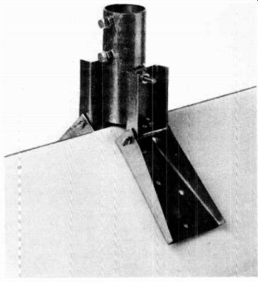
Fig. 7-5. Roof peak mount.
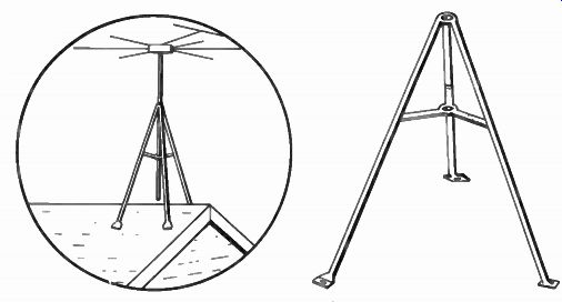
Fig. 7-4. Tripod roof mount.
Vent pipes are very secure methods of holding a tv antenna mast. Vent pipes are usually four inches in diameter, and extend through the roof from bathrooms, the laundry area, or kitchen. A two-piece clamp for holding the mast is best. This is the type of clamp used to install the antenna shown in Figs. 7-1 and 7-2.
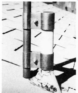
Fig. 7-6. Two-piece vent pipe clamp.
Fig. 7-6 shows the bottom of the mast fastened to a vent pipe, using this type of vent clamp. Fig. 7-7 is a view of the antenna installed and with lead-in connected. The clamps (Fig. 7-6) are each held by a single bolt, and tightening it tightens both the part of the clamp which holds the tv mast and the part which holds to the vent pipe. Mounting is easier if the mast is mounted to the clamp with the antenna off, and the antenna is mounted to the top of the mast after. This can be done by one man if a 5-ft mast is used. Using a 10-ft mast re quires mounting the antenna to the mast first, then inserting the whole assembly into the vent mount. This will usually re quire two men, one to hold the mast and antenna assembly and the other to tighten the mount. Note the mountains in the background view of Fig. 7-7. The tv station antennas are located at the top of the mountain in this city. The antenna has a fortunately good line-of-sight path. The front of the antenna, which ...
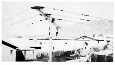
Fig. 7-7. Antenna installed with lead-in connected.
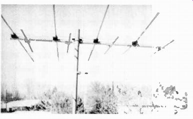
Fig. 7-8. Vhf antenna.
... in this case is the end with the uhf section, should point directly to the tv stations' location.
Fig. 7-8 shows a vhf antenna. The city in which this antenna was installed does not have uhf service, and the distance between this home and the tv stations is greater than for the example shown in Fig. 7-7. Therefore, an antenna with more elements and without the uhf section was chosen. The method of mounting is otherwise the same. The end of the antenna with the shorter elements is considered the front, and that is the end that is orientated to point to the tv station location.
Mounting the antenna to the mast is done by means of a U bolt. The curve of the U goes around the mast, and the double bolt runs through the boom of the antenna. Two nuts with lock washers secure the U-bolt.
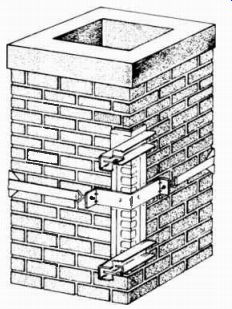
Fig. 7-9. Chimney mount.
CHIMNEY MOUNTING
One of the most common methods of mounting a tv antenna is to attach it to the chimney. A number of mounting hardware types are available for this. All use the principle of banding the chimney with stainless steel straps and securing, by means of the bands, the mounting hardware that holds the tv mast.
One of the best chimney mounts is shown in Fig. 7-9. A single strap holds a V-shaped vertical piece to the chimney. The V-shaped part against the chimney corner is . 05 inch aluminum. This is fastened to an embossed horizontal section of 12 gauge steel. U-bolts in the horizontal sections hold the tv mast.
Fig. 7-10 shows the popular Z-mount, the separate parts of which are in the photo of Fig. 7-11. A set of two Z-mounts is required to hold a tv mast.
Both of the mounts above use eye-bolts with one side flat to hold the stainless-steel straps. Nuts on the threaded parts of the bolts draw the straps up tight around the chimney.
The ratchet chimney mount of Fig. 7-12 also uses straps around the chimney, but it employs a different method of tightening the straps. A ratchet system, detailed in Fig. 7-13, pulls up tight on the strap when turned by a wrench. The idea is a clever one, and some may think this is an easier method of tightening the straps. The nut method of tightening is a little slower but is just as secure when done.
If the chimney is brick, and it appears that some of the mortar has loosened from aging, it would be best to have it tuck pointed before installing a chimney mount. A poor mortar condition can be made worse from the wind whip on a tv antenna when mounted to the chimney.
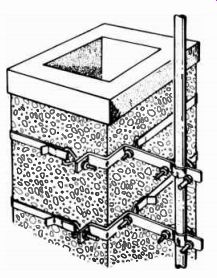
Fig. 7-10. A Z- type chimney mount.
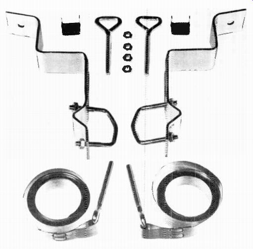
Fig. 7-11. Separate parts of a 2- typed chimney mount.
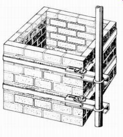
Fig. 7-12. Ratchet chimney mount.
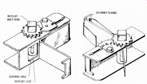
Fig. 7-13. Ratchet system details.
WALL MOUNTING
If it is desired to mount the tv antenna in a place that makes it the least conspicuous, it should be mounted as far to the rear of the house as possible. Mounting it to the back wall of the house, with a mast that places the antenna above the roof line, does this. There are several wall mounts available, most of them based on the use of brackets with a V or modified U-shape to them.
Fig. 7-14 shows a wall mount. The metal is 3/16 inch thick aluminum. The two brackets are mounted one above the other to give two-point suspension to the mast. The brackets hold the mast out six inches from the wall.
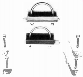
Fig. 7-14. Wall mount.
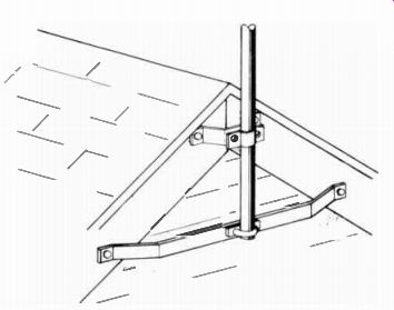
Fig. 7-15. Wall mount for a peak- roofed home.
Heavy-duty wood lag screws are all that are needed for mounting the brackets to the side of a house using wood sheathing. Try to find at least one of the vertical wall studs, and use screws long enough to reach the stud. The next stud would normally be 16 inches away, too far for the other end of the bracket to reach. With most homes built of brick or stucco, wood screws must give way to lag screws. For brick homes, it ...
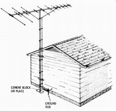
CEMENT BLOCK OR PLATE; GROUND ROD
Fig. 7-16. Grounding the mast.
... is easier to go into the mortar between the brick. For either mortar or stucco, a hole must be drilled or pounded out and a wood or lead insert placed in the hole. The lag screw is placed into the insert, which expands as the screw is tightened. Holes can be made with a carbide-tipped drill bit, or a star drill and sledge hammer. Stucco is concrete about one inch thick. The brackets should be spaced apart about 20% of the length of the mast used.
A sidewall bracket that avoids the need for going into brick or stucco is the one shown in Fig. 7-15. This type is wood screwed to the facia at the end of the house with a peaked roof. The lower element is 48 inches long, to reach across. The bracket has a three-inch offset to clear any louvered vent windows.
Mounting to the side of the house has one special advantage in lightning protection. A ground wire can be run straight down to a rod in the ground, providing a short and straight run for best protection. Fig. 7-16 shows the use of a gas or water pipe for a mast, run all the way down to the ground level, where it is connected to a ground rod. The bracket of Fig. 7-14 will take pipes as thick as 2 1/2 inches by omitting the make-up block, as shown in Fig. 7-17.
MAST MOUNTING
Where greater height than can be provided with a standard five- or ten-foot mast is required, telescoping masts in 20-, 30-, and 40-foot lengths are available. Telescoping means the mast is supplied in several sections, each with a smaller diameter, so each fits inside the other. The mast sections are steel, galvanized protected, and with a coating of zinc. In spite of its ...
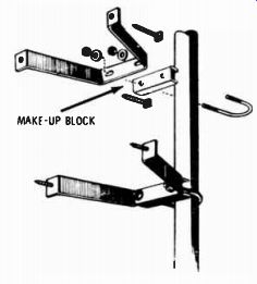
Fig. 7-17. Make-up block.
(A) Twin lead. (B) Coaxial cable.
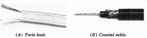
Fig. 7-18. Lead-in cable.
... steel construction, the total weight of the 40-foot mast is only 33 lbs.
Because of the greater height of masts, they must be guyed.
Guying rings are supplied with the masts, for attaching the guy wires.
Section 5 on fringe area antennas covers the raising of masts.
RUNNING THE LEAD-IN
The two principal types of lead-in were discussed in previous sections. As a review, the two types are shown in Fig. 7-18.
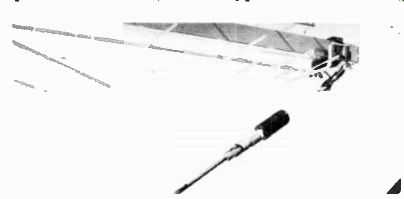
Fig. 7-19. A 300- to 75-ohm transformer and protective boot.
The round, black cable is coaxial 75-ohm cable. The flat-looking wire is 300-ohm twin lead. The coaxial cable features the shielding of one lead with an outer lead of braided wire. This and the fact that it is round makes it easier to run from the antenna to the tv set; it is not affected by nearby wires or noise-producing equipment. The 300-ohm lead-in is also avail able in a shielded type, but it is more commonly used as shown in the photo.
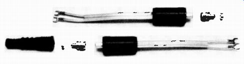
Fig. 7-20. Impedance-matching transformers.
The antenna installation of Fig. 7-7 shows the coaxial cable used for the lead-in. Because the antenna is designed for 300 ohm lead-in, and the coaxial cable has a characteristic impedance of 75 ohms, a transformer must be used to change one impedance to the other. This can be seen in greater detail in the photo of Fig. 7-19. This transformer has a rubber jacket over the cable plug to protect it from moisture. An identical transformer is used at the tv set to change the impedance back from 75 ohms to 300 ohms, the impedance of the tv set input.
Being indoors, no rubber jacket is used on the cable plug. The Radio Shack lead-in package consists of a pair of transformers, two plugs for installing onto the cable, and one rubber jacket.
It includes instructions for installing the plugs on the cable.
The complete set is pictured in Fig. 7-20. Fig. 7-21 is a closeup view of a plug installed onto the co axial cable. Some of the outer rubber cover is cut away. Then the shielding is cut away, followed by some of the inner insulation between the inner conductor and shielding. This is shown somewhat exaggeratedly in Fig. 7-21. A ring-shaped ferrule supplied with the plug is slipped over the cable. The neck of the plug is slipped between the braided shield and the inner insulation, the ferrule is moved down over the braided wires and crimped tight with some pliers. This makes connection between the shell of the plug and the shield. The inner conductor fits through a small hole in the plug and protrudes slightly out the front. The wire itself becomes the center pin of the plug.
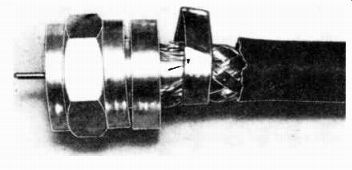
Fig. 7-21. Coaxial plug.
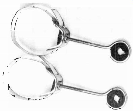
Fig. 7-22. Standoff insulators using stainless steel straps.
On 300-ohm twin lead, some of the insulation is stripped away from the two wires, exposing about 3/4 inch of wires.
Twist the wires in the direction in which they are normally twisted in the cable, and bend a hook on both of them. Hook the wires under the screws at the antenna and at the tv set and tighten down on the screws.
Both types of lead-in must be supported every few feet with standoff insulators, to prevent their being whipped by the wind, and, in the case of the 300-ohm twin lead, to keep it away from metals. In addition, the 300-ohm lead must be twisted about five turns every yard. This gives equal capacity effect exposure to any metals that may be nearby, and maintains a balanced con dition in the two wires.
STANDOFFS
Different standoffs are used for fastening to different types of structures. The photographs that follow show them. however, the black circular part of the insulators are all the same
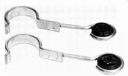
Fig. 7-23. Standoff insulators using hook snaps.
and are designed to take any kind of cable. They are slotted on one side, and they turn in the metal part that encircles and holds them. The cables are attached by turning the insulator to where the slot is in line with the open part of the metal, and the cable is forced into the center through the slot. After the cable is in, the insulator is turned so the slot is opposite the metal opening. This prevents the cable from coming out of the insulator. However, the slot in the insulator is too narrow to insert heavy cable such as coaxial and shielded 300-ohm twin lead while bound by the metal ring. For heavy cable, remove ...
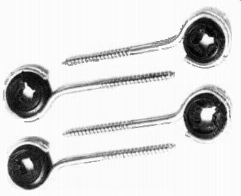
Fig. 7-24. Standoff insulators using wood screws.
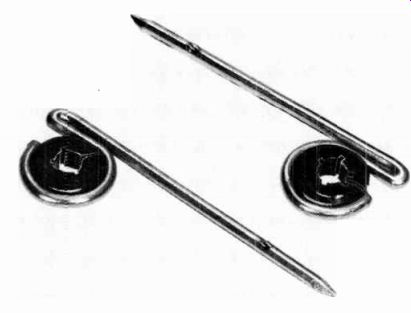
Fig. 7-25. Nail- in, standoff insulators for wood
... the insulator by pressing it out, then insert the cable into the insulator, and reinstall it into the ring of the metal holder.
The standoffs in Fig. 7-22 are for mast mounting. They are also shown in Figs. 7-7 and 7-8. The straps on the standoffs are of stainless steel and are fastened at one end. The strap is placed around the mast, and the other end threaded through slots in the base of the standoff. Tightening down on the screws tightens the strap. Another mast type standoff is shown in Fig. 7-23. The hooked part is spring steel and merely snaps onto the mast.
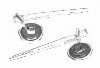
Fig. 7-26. Nail- in, standoff insulators for mortar.
The standoffs in Fig. 7-24 are for fastening to wood. A pilot hole should first be drilled into the wood, to make inserting and tightening easier. This practice is good for any wood screw.
Those shown in Fig. 7-25 are also for wood. They are pounded into the wood like a nail. Note the reverse bend at the top for taking the hammer blows. A crimp on the shank, a short distance from the point, makes a firmer fit when the nail is hammered home.
Fig. 7-26 shows mortar-type nails as part of the standoff.
Like any mortar nails, they have blunt ends and square shanks.
They are easily driven into the mortar between bricks and will also go through concrete, with extra care. But they are primarily intended for fastening into mortar. Use a short-handled sledge hammer and drive them firmly but carefully. The mortar gives way and compacts around the shank for a firm hold.
LIGHTNING PROTECTION
Because a tv antenna is usually the highest point on a house it could be struck by lightning if allowed to stand and accumulate a static charge. During a thunderstorm static can accumulate. The chances of lightning striking the antenna are considerably reduced if the static charge is drained off. This is done by grounding the antenna. If by chance lightning should strike the antenna, the charge will be carried to the ground on the outside of the house instead of through the house. Furthermore, most insurance codes require that tv antennas be grounded.
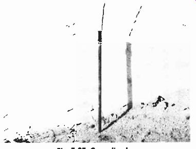
Fig. 7-27. Grounding bar.
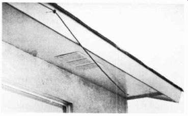
Fig. 7-28. Coaxial lead-in entering an attic.
Grounding merely means running a wire from the mast of the antenna to a rod driven into the ground.
Large conductor wire should be used for the ground wire. It need not be copper, although copper is preferred. The usual type of ground wire is aluminum, only because it is much more easily handled in the large sizes.
Loosen one of the bolts that support the mast and hook the ground wire around it. Tighten the bolt again. Run the wire over the roof and down the side of the house along the shortest path between mast and ground. Drive a metal rod into the earth ( Fig. 7-27) and twist the other end of the wire around it near the top. If copper wire is used, it may be soldered to the rod with a blow torch and resin-core solder ( never use acid-core solder for electrical connections), as was done in the photo of Fig. 7-27. If aluminum wire is used, purchase a special clamp, any one of the many types will do. The clamps are similar to those used by electricians or telephone installers for grounding wires to water pipes.
Ground rods should be six or eight feet in length. The best ones are steel with a copper-clad overall. One end is tapered for easy driving. In areas where the soil is hard and dry you may need to place a hose at the location and let a trickle of water run for a while to soften the earth enough for driving the rod into it. Dry soil is not a good electrical conductor, but it becomes wet in a rain storm and will then make a good soil for lightning protection.
RUNNING LEAD-IN INDOORS
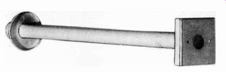
Fig. 7-29. Plastic wall tube.
If the lead-in cannot be brought through the attic and down an inner wall, as shown in the photo of Fig. 7-28, the next best thing is to go through the outside wall of the house. This is done by means of a "wall tube," as illustrated in Fig. 7-29. This feed-through type of device is all plastic, takes any kind of lead-in, and will fit walls up to 13 inches thick. It includes a rubber grommet for the outside flange, which makes the fit weatherproof.
If the outside wall is brick, select a point at a corner of the bricks and pound a hole through the mortar with a star drill.
If your home is frame and veneer brick ( one thickness of brick), determine where a stud in the wall is by means of a magnetic device to identify plaster-holding nails in the studs.
These magnetic detectors are inexpensive and may be purchased at any hardware outlet. When going through the mortar between the brick, select a point that won't strike a stud inside.
An all-brick home will have two or more thicknesses of brick, and 3 / 4 inch furring strips between the brick and plaster walls.
A star drill will go through the furring strip without trouble.
The inside end of the wall tube is made to accommodate the wall socket illustrated in Fig. 7-30. Thread the 300-ohm twin lead through the wall tube, fasten it to the terminals of the socket, and fasten the socket to the wall tube. No soldering is required.
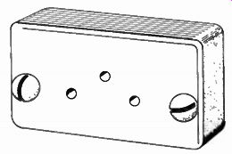
Fig. 7-30. Wall tube socket.
A mating plug, supplied with the socket mentioned above, is then connected to a 300-ohm twin lead long enough to reach the tv set. The plug, also, requires no soldering. If the tv set is not near the socket, you may find it necessary to run twin lead along the molding to the location of the tv set. Special tacks are available to do this, and the installation is quite inconspicuous.
If the lead-in can be brought through the attic and down a wall, the installation can be much more professional looking.
There is more work involved, however. The work has to do with dropping the cable down inside the wall.
The inside walls of homes are usually made of 2 x 4 studding with plaster board fastened to both sides. Across the top of the studs are one or two thicknesses of 2 x 4 called a plate. On inspection you will see electrical conduit, or un-piped electrical cable, going through places in the plate that are exposed in the attic. If you are using coaxial cable, or shielded 300-ohm line, you can thread your cable through the same cuts in the plate as the other services, and there is usually enough extra room to do this. For unshielded 300-ohm line you must drill a new hole and keep the line away from any other cables or metallic objects.
Some city codes require home construction to include fire breaks in the walls. These are horizontal pieces of 2 x 4 set in about halfway down the wall. If these are present in your walls, you have a problem. The only way to go through these fire break pieces is to drop a weighted string down the hole in the plate and estimate the distance down for the firebreak piece.
Then, chop some plaster away inside the room at the point where the firebreak is, notch the wood to allow the cable to go around it, and re-plaster and repaint the wall.
Homes with basements or crawl spaces under them can use the method described above, but working up from the space beneath, through the sill on which the studs rest. The sill is similar in construction to the plate mentioned. Where fire breaks are used in walls, working from a crawl space or basement beneath avoids the problem, as it is only necessary to go about a foot above the molding.
The lead-in may be brought through a wall by cutting a small hole just large enough to accommodate the cable. Estimate the entrance to be as near to your tv set as possible. A preferable method is to install an electrical box and use a socket wall plate, described below. Electrical boxes are available for support by the plaster will itself, as well as by nailing to studs.
If you are planning on building, or are in the process of building a new home, the time to put in tv cables is when the house is fully framed, but before the plaster walls have been installed. The work of running cable in the wall is very easy at that time.
WALL MOUNTING SOCKETS
A neat indoor lead-in installation is the end result when cables are run in the wall and terminated in a wall mounting socket. The finished look is like that of an ac outlet of your house wiring system. Fig. 7-31 shows one of several plates available. Some fit the standard electrical outlet boxes, as mentioned above. Others are made for surface mounting onto the wall, and no box is needed behind them. The one in Fig. 7-31 ...
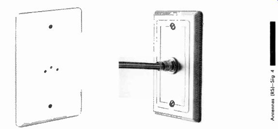
Fig. 7-31. Wall plate receptacle for Fig. 7-32. Wall plate receptacle
for twin- lead cable, coaxial cable.
... is for box mounting, which puts the plate flush against the wall.
This one is made to accommodate a matching plug, for use with one 300-ohm twin line. Another has two sets of terminal holes for taking two plugs, for use either when two separate antennas and lines are used, one for vhf and one for uhf (most tv sets have separate input terminals for vhf and for uhf), or for a single line with a splitter mounted behind the plate.
Some plates have terminal combinations for connecting a tv set and a multi-cable line to a rotor. Matching plugs are avail able for both.
Fig. 7-32 is a photograph of an actual installation of a plate with coaxial cable termination. The wall is too light in color to be recognized as a wall. The type of plug shown in Fig. 7-21 screws into the receptacle.
CONNECTING THE TV SET
The point where the lead-in is brought into the house should be as close to the tv set as possible. Whether it is terminated in a wall socket, or brought through the wall in a continuous piece, the lead-in must filially end at the tv set.
If a wall plate is used, a length of cable just long enough to run from the wall to the tv set must be made up. The wall plate has a three-hole socket for each tv set. The mating plug for it has three pins in the form of a triangle. The two wires of a length of twin lead are connected to the two pins farthest apart. The third pin merely adds a better grip to the plug when in the socket. Skin the insulation off the two wires far enough to permit inserting the wires into the pins so they will reach a little beyond the location of the side screws. Insert the wires and tighten the screws.
At the other end of the cable, the insulation is skinned from the two wires and fastened to the screw terminals on the back of the tv set. Twist the wires in the direction of their natural twist, and place them around the terminals in a clockwise direction, then tighten down on the screws.
Color sets usually have two sets of terminals, one for vhf and one for uhf. A splitter must be used to divide the signal between the two inputs. One is furnished with all Archer vhf/ fm/uhf antennas, or it may be purchased separately. Splitters have two short stubs of twin lead, each ending in spade lugs.
One is marked for the vhf input on the tv set, and one is marked for the uhf input. At least one set of screw terminals is on the case, for the main tv lead-in cable.
Next: INDOOR TV ANTENNAS
Prev: MULTIPLE-SET DISTRIBUTION
AMAZON multi-meters discounts
AMAZON oscilloscope discounts
Also see:
Industrial Electronics (in the early 1960s)
199 Electronic Test & Alignment Techniques (1972)