Measurements of direct current (dc) are made with a VOM or a VTVM. VOM stands for volt-ohm-milliammeter, an instrument which performs the function of measuring volts (both d-c and a-c), resistance, and current. A switch not only selects the functions of the VOM, but selects the ranges of each function (Fig. 1-1). The basic meter movement deflects a needle mounted on a coil, the needle moving a distance proportional to the current passing through the coil. High-value resistors in series with a basic meter movement establish different ranges for reading volts. Shunt resistors bypass some of the current so that the instrument can indicate more current than the basic meter movement can take. Batteries and resistors in series set up the circuit for reading the value of an external resistor.
SENSITIVITY
When making voltage measurements in high-resistance circuits, such as at the plate of a vacuum-tube audio amplifier, it is important to draw the least amount of current to deflect the needle on the meter.
Otherwise, the voltage read will be inaccurate due to the extra load.
If a 1-mA basic meter movement is used in a VOM, a 100,000-ohm multiplier (series) resistor will cause the meter to be deflected to full scale with 100 volts applied to the VOM test leads (OHM's law tells us that 100 volts through a 100,000-ohm resistor produces a current of 1 milliampere). An instrument with a 1-mA meter movement is called a 1000 ohms-per-volt VOM. Better VOM's are 5000 ohms/volt and 20.000 ohms/volt. To keep the loading effect of the instrument down, and for working with transistors, the amateur should seriously consider buying the 20,000 ohms/volt VOM especially since some inexpensive imports are now available with this sensitivity.
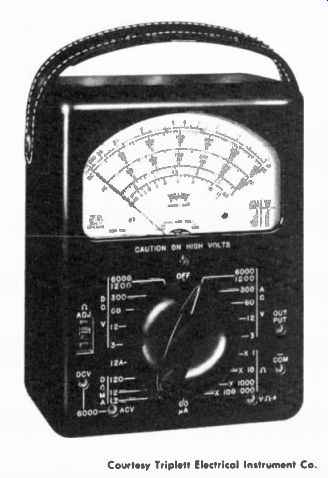
Fig. 1-1. The Triplett Model 630 VOM is typical of many of the better 20,000
ohms/volt VOM's. Courtesy Triplett Electrical Instrument Co.
VOM vs. VTVM
Where high sensitivity is important the logical instrument is the VTVM (and the solid-state equivalent). VTVM stands for vacuum tube voltmeter. Most of them have a constant input resistance of 11 megohms on all ranges. There is hardly a circuit in which an 11 megohm load will alter the readings to any appreciable degree (Fig. 1-2 The VTVM uses two triodes in a bridge circuit with the meter movement connected between the cathodes of the two triodes. The grid of one triode is connected to ground, and the grid of the other triode connects to a bank of voltage-divider resistors at the input. The string of voltage-divider resistors in series totals 11 megohms. The range switch selects a portion of the voltage on the string, the position depending on the range. Any voltage above ground results in the cathode current in one triode being different from the cathode current in the other triode, with a consequent voltage difference between the two cathodes. This upsets the balance and causes the meter to indicate.
The resistor bank in the instrument actually totals 10 megohms. There is a 1-megohm resistor in the tip of the d-c volts probe to make a total of 1 I megohms. The 1-megohm resistor in the probe isolates the test-probe cable capacitance (a shielded cable is used to keep stray ac from affecting the reading) and the instrument itself from the circuit under test. A VTVM has no current-reading function.
SOLID-STATE VTVM
The standard VTVM depends on the 120-volt a-c supply for its primary operating voltage. With the improvements in transistors (especially the high-impedance FET's), the selection of battery operated VTVM-type instruments is increasing every day. Most have a VTVM I 1-megohm input resistance, like that of the a-c operated VTVM, and other functions are very similar (Fig. 1-3). The solid state instruments employ two or four transistors in a bridge circuit. Portability is the principal advantage of the solid-state instrument.
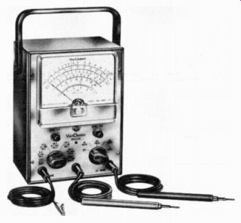
Fig. 1-2. One of the most popular of standard VTVM's is the RCA Volt-Ohmyst.
This Model WV-77E is also available in kit form. Courtesy RCA Courtesy Triplett
Electrical Instrument Co.
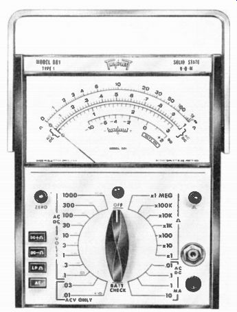
Fig. 1-3. The Triplett Model 601 has functions and sensitivity like a standard
a-c VTVM, but is battery powered. Because it also includes a current-reading
function, it is called a solid-state VOM. INSTRUMENT ACCURACY.
Accuracy depends on two things: the quality of the meter movement, and the tolerance of the resistors. Typical accuracy specifications on the better instruments are 2 percent on dc and 3 percent on ac.
The 2-percent accuracy on de will usually mean the manufacturer is using 1-percent resistors and a 1-percent meter movement. Incidentally, accuracy figures on meter movements means accuracy of full scale. That is, the 500-volt scale may have a 5-volt error at any part of the scale. You can see that the same 5 volts at the low end of the scale can be a high percentage of the figure being read. The change in the accuracy figure of ac means the rectifier has some tolerance of its own and adds to instrument inaccuracy.
LOADING EFFECT
If the source of the voltage being measured has high resistance in it, a VOM can show an error in its reading because it represents an additional load at the point of measurement. Fig. 1-4 is the schematic ...
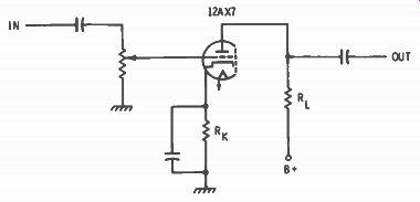
Fig. 1-4. A standard audio-voltage
amplifier using one triode of a 12AX7.
... of a triode audio-voltage amplifier. The plate-load resistor (RL) is 100,000 ohms. A 1000-ohms-per-volt VOM set for 100 volts is connected to the plate for a voltage measurement. On the 100-volt range, the total series resistance in the instrument is 100,000 ohms, as explained previously. Assume a 100-volt power-supply source. If the tube were pulled out, there would be no current drawn through the plate-load resistor, and the plate side should have a voltage of 100 the same as the supply voltage. But if you connect the VOM to the plate terminal, it will read only 50 volts, because its internal 100,000 ohms is in series with the 100,000 ohms of the plate-load resistor, and at the test point the voltage is one half because there is now current drawn. The current through the meter is now 100 volts divided by 200,000 ohms (100,000 + 100,000) or 0.5 mA. This current through the plate-load resistor equals 50 volts and that is what your meter will indicate. Now, reinsert the tube. It, too, draws current and will look like a resistor, probably about 100,000 ohms. With the tube in the circuit the plate voltage should read 50 volts, but as soon as you touch the VOM probe to the plate you have shunted the tube with an additional 100,000 ohms, so it will look like a 50,000 ohm resistance (two 100,000- ohm resistors in parallel) in series with the plate-load resistor. The total resistance is now 150,000 ohms and the voltage across the 100,000-ohm plate resistor will indicate only 2/3 of the 50 volts actually there, and this is a 33.3-percent error.
A VTVM, on the other hand, is an 11-megohm load, which reduces the effective resistance by only about 1-percent and results in a 1-percent error in measurement at this point. Go through the mathematics as we did for the VOM, and you will see the difference.
Wherever high-value resistors are used in circuits, a high-impedance VTVM will reduce the error in the measurement of direct current. In addition to the plate circuit of a vacuum-tube audio voltage amplifier, there may be occasions for measuring at the grid. Some audio amplifiers, although not usually in ham equipment, use what is called "con tact-potential" biasing for the vacuum-tube amplifier (Fig. 1-5).
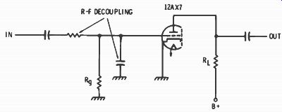
Fig. 1-5. Audio amplifier using contact-potential
biasing, created by the space charge between grid and cathode. A very high
value for R_G is required.
In these circuits the cathode is grounded and the grid is returned to ground through a 5- or 10-megohm resistor. Electron space charge in the tube creates a bias. Even the VTVM does not measure this voltage accurately, but still will measure it much more accurately than will a VOM, which becomes practically a short circuit for this bias arrangement.
PRACTICAL DC MEASUREMENTS
Ham equipment usually comes with an operating manual which also includes a chart of voltages for various terminals of the tubes, if tubes are used. The sensitivity of the measuring instrument is usually indicated. Generally it is assumed a 20,000-ohms/volt VOM is used. The readings given are for voltages with respect to ground, and may be positive ( + ) or negative ( - ) dc with a-c readings for the heaters, and for the plates of a tube rectifier if one is used. If your voltage readings agree with the chart, it is assumed that all tubes are functioning properly. This is one of the best methods of servicing a receiver or transmitter.
Solid-state equipment is more difficult to check because of the sizes of components. If the transistors are wired directly into a printed circuit board, as they frequently are, the job of tracing transistor terminals on the underside of the board is very tedious. Many pieces of solid-state equipment include test points along the circuit. These are short stubs of heavy wire sticking through the topside of the printed-circuit board identified by printed letters on the board. Many of the test points are there for alignment purposes as well as for volt age check points.
VACUUM-TUBE AMPLIFIERS
Even without a voltage chart it is easy to determine the performance of the active components of ham equipment (active components are tubes, transistors, and relays; passive components are resistors, capacitors, etc.). Comparing voltage readings with specs in a tube or transistor manual can tell you whether such active components are performing as they should.
Fig. 1-6 is the schematic for a popular output stage in a receiver.
It uses a single 6K6GT tube, capable of an output of about 3 to 4 watts. A typical voltage supply value to the tube is 250 volts. This would be read at point #2. R, is a cathode-biasing resistor. The volt age drop across it is the bias voltage between cathode and grid. A typical value for this resistor is between 500 and 600 ohms, probably around 550 ohms. With the black lead connected to the chassis, touch the red ( 4- ) lead to terminal 8 of the tube socket. A reading of + 18 volts is about right. Ohm's law tells us a current of about 33 mA will ...
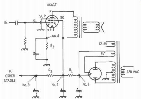
Fig. 1-6. Typical output stage and power supply as used
in some amateur receivers. Symbols and test-point numbers are described in
the text.
... produce an 18-volt reading across a 550-ohm resistor. According to the tube manual this is about right. The tube is working, that is, and there is emission of the prescribed amount for this tube in this circuit. It is assumed that you know the current in the cathode circuit equals the current in the plate and screen circuits combined. If no voltage was indicated across the cathode resistor, it would mean that the tube had lost its emission. If less than the right amount is indicated, the tube is getting soft and should be replaced. Other information from this circuit is the total current drawn by all stages in the receiver. All the current goes through the filter resistor (R,). The manual will give you the value, or you read the color code, or measure the resistance with the ohmmeter. Measure the voltage across the resistor, either by placing the positive lead of the voltmeter at terminal #1 and the negative lead at terminal #2, or by grounding the negative lead and measuring the voltage at both terminals #1 and #2 and take the difference. The voltage divided by the resistance is the current. As a rule the highest current is drawn by the output stage. To measure for the current to all other stages, measure the voltage across R2 , and divide by the resistance.
Another version of the output-stage circuit is shown in Fig. 1-7.
This is sometimes seen in transceivers because of the availability of bias for the transmitter tubes. Plate current can be measured by measuring the voltage across the primary of the output transformer with power on and then measuring the resistance with the power off. Both the voltage and resistance will be very low because you are measuring the resistance of the wire in the primary. While it is much more ac curate to measure across the primary rather than between each side and ground, be careful to place the VOM out of the way so you will not touch any part of exposed metal such as other terminals. They may be "hot" with respect to the case of the receiver or transformer. Since ...
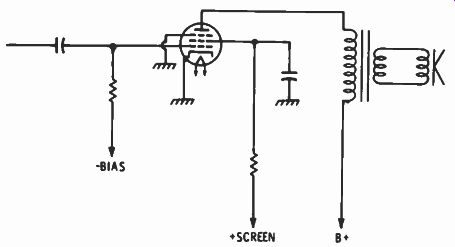
Fig. 1-7. An audio
output stage using fixed bias.
... fixed bias is used, bias measurement is directly from grid to chassis ground. A bias measurement will be the same whether the tube is OK or not. You will have to depend on the plate-current measurement described for a check on performance. If you are checking the receive functions of the tubes in a transceiver, remember to have the transceiver in the receive mode. When the transceiver is in the transmit mode, high bias is applied to some tubes in the receiver to kill their amplification while transmitting.
There are two popular forms of low-level audio amplifiers. The most used is the one shown in the schematic of Fig. 1-4. The high-/i twin triode 12AX7 is frequently the tube seen in this circuit. The tube manual will probably refer to the 6AV6 for characteristics because the triode in this triode twin-diode tube is the same as the two triodes in the 12AX7. The plate supply voltage to the tube is most likely 100 volts after the original voltage is dropped by a decoupling resistor. At 100 volts, the right grid bias is -1 volt. Measure across the cathode resistor again (Rk ), in the same way as the first example of the 6K6GT. And from this you can calculate current in the plate circuit by dividing the voltage by the resistance. The tube manual says it should be 0.5 mA. Measuring the voltage drop across the plate-load resistor and dividing by the resistance should give you the same answer, but here is where you must be careful as to the sensitivity of the instrument. It takes a VTVM or a FET voltmeter to give you any reasonable accuracy. A 20,000 ohms/volt VOM on the 100-volt scale ...
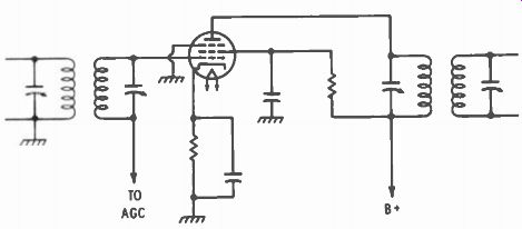
Fig. 1-8. R-f and i-f amplifiers are like audio amplifiers except
for the tuned circuits used at input and output. Fixed bias is from the cathode
resistor. Additional bias from a diode detector varies the gain for agc.
... will have a total resistance of 1 megohm. If the plate-load resistor is 100,000 ohms, as it sometimes is, the error introduced by the instrument is 10 percent.
Fig. 1-5 is the schematic of an audio amplifier often used as the microphone first stage amplifier in a transmitter, because the grounded cathode reduces hum and r-f pickup. Bias is obtained by the space charge of electrons gathering around the cathode and grid. The only way to measure bias is with a VTVM between grid and ground, and even then there will be about a 20-percent error It will be more ac curate to check for proper plate current by measuring the voltage across the plate-load resistor, and dividing by the value of the resistor.
If the answer is about 0.5 mA. you will know the bias is right.
R-f and i-f vacuum-tube amplifiers (Fig. 1-8) will also usually have cathode resistors for fixed bias. Their performance is checked by measuring the voltage across the cathode resistor as in the case of the audio amplifier. Actual bias values in i-f amplifiers are usually not the same as they are for audio applications, since there is no attempt to operate the tubes as class-A amplifiers because there is no need to.
Almost any low value of bias voltage is considered OK. When checking the bias on r-f or i-f tubes, the r-f gain control must be at maximum, and there must be no signal received, otherwise the age voltage will reduce the plate current much below that indicated by the tube manuals.
Buffer and driver stages in a transmitter are measured in the same way as r-f and i-f amplifiers in a receiver, except they often have a fixed bias on the grid. Also power-type tubes are used, so currents will run more like the audio output stage mentioned earlier. Sometimes they have a cathode resistor for protective bias and sometimes they do not. About the only way some can be checked for emission while in the chassis is to measure across the screen dropping resistor, (which most will have) and check with the tube manuals to compare screen current. A typical example is a 100-ohm decoupling resistor in the screen of a 6GK6 driver tube fed from a 275-volt supply. The voltage across this resistor measured only 0.5 volt, but Ohm's law gives us 5 mA of current which is about right, and the tube is drawing about the current it should.
An oscillator is oscillating when there is DC voltage between grid and ground. The value varies considerably and will usually be some where between -5 and -10 volts. This is grid bias due to the oscillation. If there is no bias there is no oscillation.
Nearly all output r-f power stages have self-bias as well as fixed bias. In case of excitation and fixed-bias failure, the self-bias resistor (Rk ) protects the tube or tubes from excessive current. Fig. 1-9 is similar to many used in medium-power transceivers today. Because of high voltage on the output-stage tubes, they are usually enclosed in a separate compartment, and this means CAUTION to you. When measuring voltage at the plate or plate supply, use only good-condition leads that are dry and clean of grease. Ground the negative lead ...
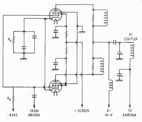
Fig. 1-9. Two tubes in parallel in an r-f output stage. R_K is a cathode resistor
for self-bias to limit plate current.
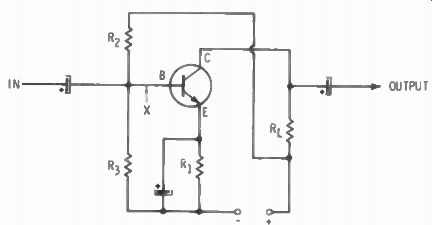
Fig. 1-10. Most frequently used transistor amplifier circuit as a low-level
stage. The resistor symbols are explained in the text.
... to the case or chassis, and place one hand behind your back when you apply the positive probe to the plate or plate supply. Be sure your meter is set on a range high enough to measure the expected voltage.
Again current is measured by measuring the voltage across the cathode resistor and using Ohm's law. To check for balance between the two tubes in a parallel-connected output stage (or push-pull) measure the voltage drop across each screen-decoupling resistor.
TRANSISTOR CIRCUITS
There are two basic differences between vacuum tubes and transistors. and these differences affect the measurements made on transistors. Transistors are current-amplifying devices; the current in the collector circuit is controlled by the current in the base circuit. The second difference is that no current flows in the collector until the base is forward-biased. There is an important exception, and that is the field-effect transistor (FET). This transistor has all the attributes of a vacuum tube.
In addition to the above, the conventional transistor is a low-impedance device. A low. low-voltage full-scale range is desirable. High sensitivity as a milliammeter is highly desirable since base currents in a transistor are frequently in the microampere range.
The schematic of Fig. 1-10 shows the basic circuit of most amplifiers using a conventional transistor. While an audio amplifier is shown, the same method of biasing is often used for r-f and i-f amplifiers. In an r-f or i-f amplifier, the load resistor (R b) would be re placed by the primary of a transformer, and the capacitors would not be electrolytics.
Note the use of both fixed and automatic bias. R. and R, form a voltage divider for fixed bias to the base of the transistor. R, carries current from both the collector and base, and so serves to create automatic bias, the same as a cathode resistor on a vacuum tube.
It might be well to review for a moment the reason for the double method of biasing a transistor. The voltage divider supplies the for ward bias needed to establish the right amount of current flow in the collector circuit. In this circuit the voltage at point X (the base) will be positive ( + ) with respect to the emitter. When current flows in a transistor, heat is developed internally. As the transistor warms up, current increases. This could continue until the transistor is destroyed if some method to stop it were not used. This is called thermal run away. Resistor R, in the emitter circuit develops a "bucking" bias voltage. It is in opposition to the fixed bias of the voltage divider.
Since current tends to increase due to heat within the transistor, the bucking bias increases and reduces the forward bias from the voltage divider, which, in turn, tends to reduce current through the transistor.
When the right values for R,, R., and R are selected, the current through the transistor is stabilized at the correct value.
Collector current is measured by measuring the voltage across load resistor R, and dividing the voltage by the resistance. Bias voltage is measured between base and emitter. The specs in a transistor manual give base current, which can best be measured by breaking the connection to the base at point X and inserting the milliammeter function of the VOM in series with the base. This is almost impossible to do in manufactured equipment. This method should be used in experimental breadboard setups for determining the right values of resistors for biasing. For measuring bias current in commercial equipment, find the collector current and emitter current from the voltages across R,. and R,. The difference between the two is base current.
TRANSISTOR OSCILLATORS
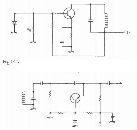
Fig. 1-11. A transistor crystal oscillator. Biasing is similar to the amplifier
of Fig. 1-10. D-c voltage across R.-, will be different between the oscillating
and non-oscillating conditions.
Fig. 1-12. A common-base configuration of a transistor in a vfo circuit.
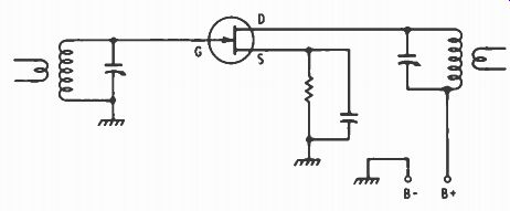
Fig. 1-13. A FET transistor as an r-f amplifier acts like a vacuum tube.
Oscillation is easy to achieve in a transistor. Almost any input and output circuit resonant to the same frequency will oscillate. A typical crystal oscillator is shown in the schematic of Fig. 1-11. Note, again, the similarity of biasing to that of the amplifier. Fig. 1-12 is a vfo as used in the Swan 500 and uses the common-base configuration. If you are using a VOM, wrap one pigtail of a 10,000-ohm resistor around the test probe. Ground the other probe. Touch the other resistor pig-tail to the emitter. Alternately place a short across the resonant circuit, and lift the short. A difference in voltage read means that the circuit is oscillating. The 10,000-ohm resistor isolates the VOM from affecting the r-f circuit. A VTVM already has an isolating resistor built into the probe.
Fig. 1-13 is a FET transistor amplifier. It is almost always an r-f amplifier because its high impedance docs not load down the resonant circuits. Note the similarity to vacuum-tube circuitry. The elements are called gate, drain, and source instead of base, collector, and emitter.
The voltage across the source resistor is the bias value, and dividing the voltage by the value of the resistor will give you the current through the drain-source circuit.
BATTERIES
The open-circuit voltage reading on a new battery should be the rated voltage of the battery. As soon as a battery is connected into a circuit a load is applied, and the open-circuit voltage value will drop a small amount. This is due to the internal resistance of the battery. As batteries deliver power and the internal chemical action begins to be used, the internal resistance increases still more, resulting in a still further drop in voltage delivered to the load. The end-of-life of a 1.5 volt battery is considered to be at 0.9 volts. The actual number of hours a battery will last depends on its size, the current drawn, and the duty cycle-that is the ratio of on time to off time. Zinc-carbon batteries cannot take continuous drain too well, but do have pretty good recovery when off for a while. Other types are able to operate continuously with good service.
The curves of Fig. 1-14 show the hours of service that may be expected of the AA size manganese-alkaline battery. Note the rather fast initial drop in voltage in the top curve. The AA size is a popular portable-radio battery for moderate drains out of a small package, and is excellent for ham experiments with transistors. It has a long shelf life, compared with the cheaper zinc-carbon, retaining about 80 percent of its life up to about 5 years. Measuring the voltage and current will tell you how much life is left in the battery. The industry NEDA number is 15A. Mallory's number is MN-1500, Burgess's AL-9, Eveready’s E91BP. Table 1-1 lists popular sizes and kinds of batteries, and the recommended load resistor for measuring. The resistances were selected to draw the current that would result in a total life of 100 hours for each type. The end voltage should be about 0.9 volts, except for the 9-volt transistor radio battery, for which an end life of 6 volts was figured.
Duty cycle was based on 2 hours per day for the zinc-carbon batteries, ...
NOTES: CURRENT OR A IN VALUES DETERMINED AT 1.25 VOLTS INDICATED PERFORMANCE AT 70° F ALL CURVES REPRESENT CONTINUOUS LOAD CONDITIONS. Courtesy Mallory Battery Co.
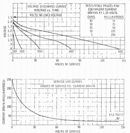
Fig. 1-14. Voltage discharge of the manganese-alkaline size AA battery under
different loads is shown in the upper curve. The lower curve shows hours of
service under different current drains.
... and continuous duty for the others. All open-circuit voltages are 1.5 volts, except for mercury which is 1.4 volts, for new batteries.
POWER SUPPLY
The regulation of a power supply is the ratio of the difference in voltage between no load and full load, divided by the full-load voltage.
Example: At no load the output measures 500 volts. With the load connected, the voltage reads 400.
-------
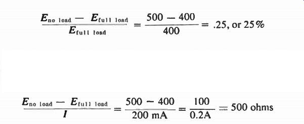
The internal resistance of the power supply is also easy to figure.
It is the difference between the no-load voltage and full-load voltage divided by the current. Example, with the same voltages given above:
------
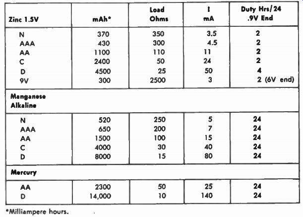
TABLE 1-1. Popular Batteries Showing Probable Life in Milli ampere Hours,
With Resistive Load and Current Shown