AMAZON multi-meters discounts AMAZON oscilloscope discounts
Obviously, a most necessary prelude to our study of regulated power supplies is an understanding of the term "regulation." In electrical engineering, "regulation" denotes the change in voltage occurring at the output terminals of a power source between no-load and full-load. The so-called voltage regulated power supplies now common in electronics incorporate automatic means for maintaining the output-terminal voltage constant despite variations in the AC line voltage or DC load current (Fig. 1-1) . In a very true sense these supplies are designed to eliminate or at least greatly reduce regulation. Therefore, when we employ the commonly accepted parlance, "voltage-regulated power supply," we pay homage to convention, but understand that such a supply is one in which the output voltage is stabilized with respect to changes in line and/or load conditions. The more effective such output-voltage stabilization is, the smaller the regulation of the power supply.
Regulation is a dimensionless quantity usually expressed as a percentage:
- No-load voltage - Full-load voltage
As an example, consider a power supply which develops a no-load voltage of 250 and delivers 225 volts to a rated load.
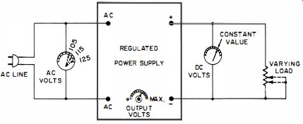
Fig. 1-1. A voltage regulated power supply can maintain a constant load
voltage despite variations in line voltage or load resistance.
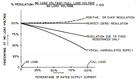
Fig. 1-2. Typical regulation curves.
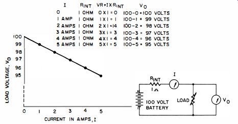
Fig. 1-3. Example of regulation due to resistance in series with load current.
The regulation of this supply is 10%:
More precisely, this power supply has a regulation of minus 10 %--the minus term conveying the information that the full-load voltage is less than the no-load, or open-circuit, voltage. Fig. 1-2 shows some typical regulation curves. You will see later that it is possible to achieve positive regulation with the load voltage rising as the load current is increased. Generally, when the minus or plus designation is not used, the implication is a voltage drop-off with load-that is, regulation in the "minus" direction. Regulation percentages between 0.001 and 1.0 are readily attainable with appropriate electronic circuits.
The need for stabilization of output voltage arises from the fact that almost any simple power supply has an inherent negative regulation. This is due to the inevitable resistance which acts in series with the load. When the load current flows through this inherent (internal ) resistance, the resultant voltage drop subtracts from the voltage delivered to the load. In Fig. 1-3 we see that a 100-volt battery supplies a diminishing voltage to the load as the load is made to consume more current. Here, R_int represents the effective resistance, which actually comprises ohmic, electrochemical, and other effects within the battery. The regulation characteristic of such a battery is also typical of generators, rectifiers, transformers, photocells, and other energy converters for supplying electrical power. Generally, the larger the batteries, rectifying devices, transformers, and other components used in simple supplies are physically, the less the internal resistance. However, any increase in bulk beyond that required from the standpoint of safe thermal operation is extremely costly and, more often than not, impractical as well.
CURRENT-REGULATED POWER SUPPLIES
Most loads encountered in electronics derive maximum benefit from operation with a voltage-stabilized source of power. This is not universally true, however. Sometimes it is of direct importance that the current be maintained constant. For example, sometimes a solenoid is used as a means of providing a steady magnetic field to an electronic device.
The strength of such a field is determined by three factors the number of turns of wire, the current passing through these turns, and the magnetic characteristics (permeability) of the medium exposed to the field. In most practical cases, current is the only factor which can suffer appreciable variation. This is particularly true because current is influenced both by the voltage impressed across the solenoid and by the temperature-dependent resistance of the windings. Energizing such a solenoid from a constant voltage supply will not stabilize the magnetic field strength, whereas operation from a stabilized current source will. An example of a current-carrying solenoid from which a constant magnetic field strength is desirable is the focusing solenoid employed in conjunction with certain traveling-wave tubes. When a current-regulated power supply is used, the current remains at a fixed value with respect to wide variations in load resistance and, generally, considerable fluctuations in line voltage.
The voltage delivered by such a supply has such extremely poor regulation that its use is prohibited with voltage-sensitive loads.
The concept of percentage regulation is used in a slightly different manner with current-regulated power supplies. We cannot paraphrase the relationship for voltage regulation by stating that current regulation is equal to the difference between no-load and full-load currents divided by no-load current, because no-load current is always zero and hence a meaningful quotient is not mathematically obtainable. In order to specify the figure of merit of current regulation, we compute the percentage change in currents between two specified loads. One is generally zero resistance, or a short circuit. The other is then a certain numerical value of resistance. Let In represent the current which flows when the output terminals of the supply are short-circuited, and I_u, the current which flows when resistance R is connected across the output terminals. Then we can designate percentage current regulation as follows:
Current Regulation (from zero resistance to R) = 10
- II: X 100 I ..
For example, suppose a current-regulated power supply delivers 5 amperes under a short-circuit condition-that is, when an ammeter is connected across the output terminals.
When a 10-ohm load is connected across the output terminals, the current flow is reduced to 4.
8 amperes. The percentage of current regulation between a short circuit and a load of 10 ohms is : 5
- 4
8 x 100 = 4'70 5
OUTPUT RESISTANCE
In voltage-regulated power supplies, the output resistance is the ratio of a change in output voltage to a change in out- put current, with the line voltage maintained constant. In Fig. 1-4, R is varied to change the output current ; the resultant change in output voltage is derived from the corresponding voltmeter indications. A voltage-regulated supply with perfect (zero percent ) regulation would have an output resistance of zero ohms because a current change would not be accompanied by a voltage change. The magnitude of the current change should be stated. For example, we might specify the output resistance of a power supply as being 0.1 ohm from zero to full load. This value would then be understood as an average value that is valid within the specified load range.
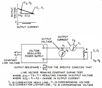
Fig. 1-4. Test setup for illustrating concept of output resistance.
The output resistance of a current-regulated power supply is similarly defined and is ideally infinite for a supply with perfect regulation. A difference in the practical determination of output resistance in the two types of supplies is that in a voltage-regulated supply, we change the load in order to change the load current and, in turn, the output voltage.
Conversely, in the current-regulated supply, we change the load to change the load voltage and, in turn, the output current. Furthermore, a current-regulated power supply cannot be so tested down to zero current ; a minimum load is required for current stabilization to exist. On the other hand, a short circuit of the output-with reduction of the output voltage to zero-is a valid test. For example, we could record a current and voltage of one ampere and zero volts for a current-regulated supply with shorted output terminals.
Next, we might observe a current of 0.9 ampere and a voltage of 20 when the load is adjusted for its nominal operating resistance. The output resistance of this supply would then be 20 volts divided by 0.1 ampere, or 200 ohms.
Dynamic Output Impedance
The most common and relevant use of percentage regulation and output resistance is to define the DC output characteristics of a power supply. This, however, is not the whole story. As a matter of fact, a regulated DC power supply is often employed primarily for its AC characteristics. By AC characteristics, we are not at this time concerned with the AC line voltage. Rather, we wii>h to know how the power supply appears to a small AC voltage impressed across the output terminals. This is a very practical parameter because many, if not most, electronic loads involve circuitry in which AC is superimposed on the steady DC operating current.
Amplifiers, oscillators, and modulators are examples of electronic "building blocks" which fall into this category.
Switching circuits, multivibrators, and logic systems involve pronounced AC components in their operation. It is not sufficient merely to be concerned with the degree of DC voltage stabilization provided by a power supply when such circuits constitute the load. The power supply is more than an incidental requirement for energizing, or establishing, the operating bias of an electronic circuit. The power supply is actually part of the circuit for both DC and AC components.
As an example, consider a two-stage audio amplifier. If the power supply appears as a high impedance to audio frequencies, it will then constitute a common impedance tending to couple the stages together in an undesired way. Such unintentional coupling is actually a feedback path allowing the intermingling of input and output voltages. This can cause oscillation, degradation of frequency response, or loss of gain. Ideally, the power supply for such an amplifier should appear as a short circuit to the whole spectrum of AC frequencies involved. Normally, a very low impedance is obtainable from a voltage-regulated supply, and this consideration may be of greater importance than the DC voltage stability defined by regulation percentage.
Dynamic output impedance can be made low, even in an unregulated supply, by means of output filter capacitors. Thus, regulation percentage and dynamic output impedance have some relationship to each other, for it is well known that large output capacitors tend to maintain the load voltage at a constant value. Indeed, a capacitor with many millions of farads of storage capacity would be practically indistinguishable from a large battery and would provide excellent regulation for relatively light loads. In practical power supplies, considerable DC voltage stabilization is of ten provided, for loads of a small fraction of one ampere, by capacitors ranging from several tens to several hundreds of microfarads. The contribution to low dynamic output impedance made by any size of capacitor becomes progressively better as the frequency is increased. Consequently, an inordinately large capacitor may be required in order to provide a low dynamic output impedance at low frequencies.
Often this situation pertains to the ripple frequency (generally 120 hz) . These considerations make electronic regulation extremely desirable-for not only is excellent (low) DC voltage regulation readily attained, but low AC dynamic output impedance is maintained through the low frequencies, all the way down to zero frequency (DC) . At the same time, many designs provide a low dynamic output impedance up to quite high frequencies as well. Often the combination of electronic voltage regulation and a relatively small output capacitor permits a low dynamic output impedance from DC to radio frequencies.
REGULATED SUPPLIES AS SEEN BY THE LOAD
A brute-force approach to zero regulation leads to an awkward predicament. If, for example, a negligible voltage drop is desired from a 12-volt battery over the load-current range of 0-to-20 amperes, it will not do merely to choose a battery capable of supplying such a current. The internal resistance of such a battery would be too high to permit the required low regulation ; a battery of many tens of times the rating needed to supply 20 amperes would be required. Indeed, if our regulating percentage were specified too low, the battery could well crowd us out of the laboratory! Herein lies the beauty of the voltage-regulated power supply ; it need only be designed for the required load. Yet it "looks" like a source of tremendous current capacity to the load (insofar as regulation percentage and dynamic impedance are concerned ; see Fig. 1-5) .
A similar situation prevails for current-regulated supplies. One having nearly zero current regulation appears to the load as a power source followed by an extremely high resistance (Fig. 1-6) . It is obvious that to actually make such a circuit would lead to gross inefficiency, for the voltage drop and therefore the power dissipation in such a resistance would greatly exceed that in the load itself. The current regulated power supply "looks" like a source with extremely high internal or series resistance. But this is where the resemblance ends, for the current-regulated supply does not incorporate an inordinately high resistance in the load-current path.
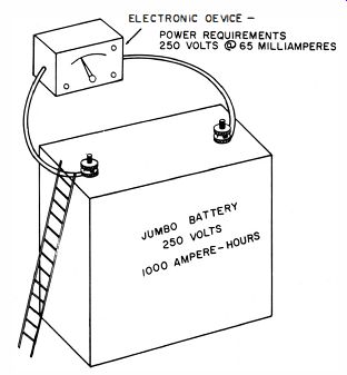
Fig. 1-5. A voltage-regulated power supply appears to the load as a tremendous
source of current, although actually it is not.
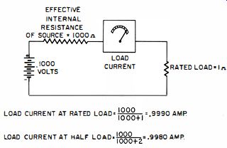
Fig. 1-6. A current-regulated supply acts as a source with a very high series
or internal resistance insofar as its current-regulating ability is concerned.
Response Time
If the load to a regulated power supply is abruptly changed, a transitory state will exist before the output becomes stabilized. There are several reasons. Shock excitation of various inductances and capacitances is frequently encountered and takes the form of damped oscillations.
Another reason is that energy-storage elements impose time constants which simply do not permit an instantaneous change in level. The inductance of the DC control winding of magnetic amplifiers is an example. Still another limitation in the rapidity of response is the relatively low frequency response of certain transistors. Instantaneous response theoretically implies the capability of infinite frequency response.
In practical supplies, amplifiers and control elements must have frequency responses in the megacycle range in order to provide a "rapid" response. When transistors having frequency cutoff characteristics of several kilocycles are used, the response time from this alone is much longer than one could obtain with a vacuum tube (assuming the current handling capability of the tube was suitable).
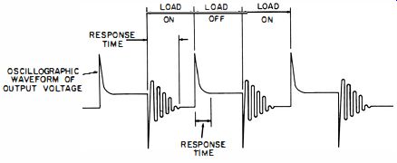
Fig. 1-7. Response time.
Fig. 1-7 provides an insight into the meaning of response time. The frequency at which the load is changed should be slow enough that the final extinction of all transient phenomena is distinctly observed. Response times for adding a load and relieving it will generally be different. The longer of the two is the more important specification because it imposes the frequency limit at which the power supply behaves as a dynamically regulated source of power to the load.
It is often stated that an output capacitor can be employed in conjunction with a voltage-regulated supply to extend this frequency (that is, to decrease the response time ). This is true in many practical situations, but may prove misleading in others. A large output capacitor does lower the dynamic output impedance, and it can decrease the response time by preventing or attenuating transients. However, the time constant involved in charging and discharging the output capacitor can, if the capacitor is large enough, slow down the response time. A similar line of reasoning applies to response time in a current-regulated power supply. Here, a series inductance can increase the dynamic output impedance, which should be as high as possible. In particular, such an inductance can take over at those frequencies at which the regulating circuitry falls off in response. However, the response time of the supply can be adversely increased by such an inductance, because time is required to change the current level in an inductance.
Response time can be specified for load variations other than from zero to full load. In such instances, the conditions should be stated ; for example, one could specify the response time of a voltage-regulated power supply as being, say, 600 microseconds when the load is changed from one-quarter to full load.
Line-Voltage Considerations
Regulation percentage is made more meaningful by relating it to a permissible change in line voltage as well as to different load conditions (see Fig. 1-8) . We might specify,
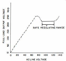
Fig. 1-8. The line-voltage range is an important consideration with regulated
power supplies.
for example, that a certain power supply exhibits a maximum regulation of 170 for a ±10% change in the line voltage. The regulation of this supply between no-load and full load could be more or less than 1 %, depending on circuit details_ Although there is a tendency for low load regulation to be accompanied by low line regulation, the two modes of stabilization are not rigorously, nor even necessarily, related.
The most difficult operating conditions for voltage-regulated supplies usually occur for the combination of low line voltage and full rated load, for it is then that the greatest tendency exists for a drop-off in the output voltage. High immunity to line-voltage variations is desirable, not only to assure a constant output voltage, but also to prevent transients and noise from being transferred from line to load. Some regulating circuits produce large voltage transients when the line switch is opened or closed. This is undesirable-particularly for operation of semiconductor devices, wherein the surge can assume destructive proportions.
Stabilization Ratio--This defines the factor by which a regulated power supply reduces the effect of variations in line voltage, divided by the resultant percentage change in DC output voltage. As an example, suppose the DC output of a 500-volt supply undergoes a total excursion of 2 volts as a result of a + 10-volt change in the AC line voltage from a nominal 115 volts. The percentage change in line voltage is 2x10 -;- 115 = 17.4. The percentage change in DC output voltage is 2 / 500 = 0.4 0/0. The stabilization ratio is then 17.4 / 0.4 = 43.5-to-1. Stabilization ratios in the tens of thousands are attainable from closely regulated power supplies.
RIPPLE
The ripple output of a supply is another definitive operating feature. If, as is usually true, full-wave rectification from a single-phase line precedes the regulating circuitry, the main ripple component will be at twice the line frequency. Sometimes an output ripple voltage is specified simply as a maximum of so many volts rms or peak-to-peak.
For instance, we might state that a particular supply developed a maximum of five millivolts rms. This would imply any line voltage, load, or combination of the two within the ratings. On the other hand, we could specify the ripple as being no more than a specified percentage of the DC output voltage. Thus, a supply might be said to have a peak-to-peak ripple voltage of no more than 0.1 % of the DC output voltage. If the DC output voltage happened to be 50 volts, then the maximum ripple voltage would be .05 volt peak-to-peak.
Peak-to-peak is a better way to define ripple than rms, because the ripple voltage is often non-sinusoidal ; in fact, sometimes the ripple waveform is characterized by spikes of fairly high amplitude. In such an instance the spikes, having a low energy content, would not contribute much to the rms value and their presence would be virtually concealed by this measurement method. A power supply rated for ripple voltage no greater than one millivolt might appear suitable for operation of sensitive equipment. However, if the one-millivolt rms rating included 20-millivolt spikes, such a supply would be likely to inject considerable noise into the equipment. A common source of such spikes is a semiconductor rectifier as it switches into and out of conduction. In current-regulated supplies, current ripple-not voltage ripple-is of primary importance. Other than this, the basic ideas are similar.
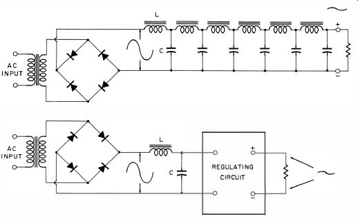
Fig. 1-9. The regulating circuit has a ripple smoothing ability equivalent
to a complex network of filter elements.
Most regulated supplies exhibit low ripple, because the automatic regulating circuitry acts on the ripple in the same manner as for any other tendency for the output voltage (or current in current-regulated supplies ) to change (Fig. 1-9) . In a very real sense, automatic regulation constitutes electronic filtering. This, indeed, is often a justifiable reason for incorporating automatic regulation. A regulated power supply can produce the same ripple suppression as several stages of large, heavy inductor-capacitor sections.
The figure of merit of ripple suppression contributed by a regulator circuit or device is given by the ripple factor.
Ripple factor is the ratio, expressed as a percentage, of output ripple voltage to input ripple voltage. That is:
where, Ripple Factor
=
E_Out X 100
In E_Out is the peak-to-peak amplitude of ripple voltage appearing at the output (load ) terminals of the voltage regulated power supply, E_In is the peak-to-peak amplitude of ripple voltage impressed by the rectifier and filter system (or other source ) at the input of the regulating circuit.
For example, suppose a full-wave bridge rectifier--in conjunction with a single capacitor as the filter element--develops 100 volts DC with a 0.1 volt peak-to-peak ripple at 120 hz. This 120- hz ripple voltage is impressed at the input of a voltage regulator. Its peak-to-peak value across the voltage-regulator output terminals is 0.001 volt. The ripple factor is then 0.001 / 0.1 x 100, or 1 % under stated load conditions.
Ripple factor is usually meant for "worst conditions," this implying full-load, but has a similar meaning for current regulated supplies-provided we substitute currents for voltages. Here, we would be interested in the peak-to-peak currents which would flow into a stated load-with and without benefit of the current-regulating circuit.
COMPONENTS EMPLOYED FOR REGULATION
Varistor A varistor is an element in which the relationship between impressed voltage and the resultant current is something other than the simple linear proportionality indicated by Ohm's law. However, not all nonlinear resistances are suitable for use as a voltage-regulating element in the shunt regulator circuit. To be useful for this application, it is necessary that the resistance of the element decrease in response to either the higher voltage impressed across it or the higher current passed through it. Thus a tungsten lamp, although a nonlinear resistance, would not perform as a shunt regulating element. The resistance of the tungsten filament increases with impressed voltage--or more precisely, with the current passed through it. On the other hand, a carbon filament lamp would provide voltage regulation when connected into a shunt regulator circuit (Fig. 1-10) . The resistance of the carbon filament fulfills the requisite of decreasing with impressed voltage. (Here again, we of course realize that the decrease of resistance is due to the elevated temperature, which in turn is due to the increased current brought about by the increased voltage.)
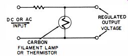
Fig. 1-10. Voltage regulation obtained by using a varistor in a shunt arrangement.
A varistor in which the resistance increases with current flow can provide voltage regulation when used in the series regulator circuit (Fig. 1-11.) However, this arrangement provides regulation against a varying line voltage only; voltage regulation with respect to a varying load resistance is poorer than if a linear resistance were used in the series arm.
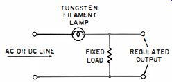
Fig. 1-11. Regulation against line voltage variations by means of a series
varistor. The forward-conduction characteristics of semiconductor diodes
such as point-contact, selenium, copper-oxide, and germanium and silicon
junction diodes, can provide a regulation percentage low enough to be useful
in low-voltage applications. Although the regulated voltage provided by a
single diode is generally less than one volt, any number of these diodes
can be connected in series-in which case the nominal value of the regulated
voltage is multiplied by the number of such series-connected diodes. However,
at four or five volts the zener diode--because of its ability to provide
much closer regulation--merits consideration.
Thyrite is the trade name of General Electric for a silicon carbide varistor. Unlike the semiconductor diode, Thyrite is non-polar. Thyrite elements are available in a wide variety of power ratings, voltage ranges, and degrees of nonlinearity. The equation defining the nonlinearity of Thyrite is: I=KV" where, I is the current through the element, K is a constant determined by the resistivity and geometry of the material, V is the voltage impressed across the element, n is an exponent, generally between 3 and 8.
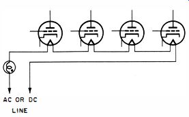
Fig. 1-12. A current ballast tube connected as shown will provide constant
current to series heaters.
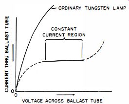
Fig. 1-13. Characteristic curve of a current ballast tube.
AC OR DC LINE
Thyrite behaves like an element in which resistivity is controlled by the impressed voltage. In most other varistors, the change of resistance is a function of current.
Current Ballast Tubes
Current ballast tubes, also known as Barretters, were among the earliest means of immunizing electronic equipment against the adverse effects of changing AC line voltage.
They remain popular as a simple and economical approach to the regulation problem, and presently are used for heater current stabilization of series-connected tubes in AC-DC radio equipment (Fig. 1-12) , for preregulation in conjunction with more complex and precise regulating techniques, and for indirectly providing voltage regulation in applications where close regulation is not necessary. This device is essentially an incandescent lamp incorporating an iron filament in a gaseous atmosphere of hydrogen. By proper choice of filament geometry and gas pressure, it is possible to design such a lamp so that its voltage-current characteristic will be as depicted in Fig. 1-13. When operation is within the constant-current region of the device, a considerable change in terminal voltage results in a relatively small change in current. Consequently, when connected in series with the AC line, the current ballast tube will provide a nearly constant current to equipment powered from the line.
When used in the primary circuit of a power transformer connected to a rectifier (Fig. 1-14) , the DC load voltage will then be substantially independent of variations in the AC line voltage. (This type of regulation is not suitable for applications where appreciable variations occur in the load resistance. Load-voltage regulation with respect to load current is adversely affected by the insertion of the ballast tube into the AC line.)
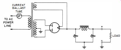
Fig. 1-14. Current ballast tube used in conjunction with a power supply.
The iron filament is subject to damage by external magnetic fields. For this reason, a magnetic shield is often used with ballast tubes. Filament temperature is below the values attained in ordinary light bulbs ; nevertheless, considerable power dissipation is involved, and attention must be given to the matter of heat removal by free convection. If ventilation is poor, the tube may not operate within its intended constant current region. These tubes are also made with filamentary materials other than iron, and with gases other than hydrogen. Unless otherwise stated by the manufacturer, these tubes should be mounted vertically, base down.
Static-Magnetic Regulating Transformers
Special transformers are also available for reducing the effects of varying AC line voltage. These transformers, when utilized in conj unction with modern silicon rectifying elements, can provide good regulation with respect to both line and load (AC line regulation of 170 and a load regulation of about 30/0 are readily achieved ). When such transformers are employed in addition to the regulation techniques described in this guide, the effect of the AC pre-regulation greatly enhances the over-all performance of the regulated power supply. Such "constant-voltage" transformers, as they are sometimes called, are particularly useful with solid-state regulator circuits, because the transistor or controlled-rectifier regulating element need not absorb the excess power whenever the line voltage rises. Further protection is conferred by limiting the short-circuit current of the constant voltage transformer to about twice the normal full-load current.
(A) Wiring arrangement. FLUX IN PRIMARY PORTION OF CORE FLUX IN SECONDARY PORTION OF CORE SECONDARY
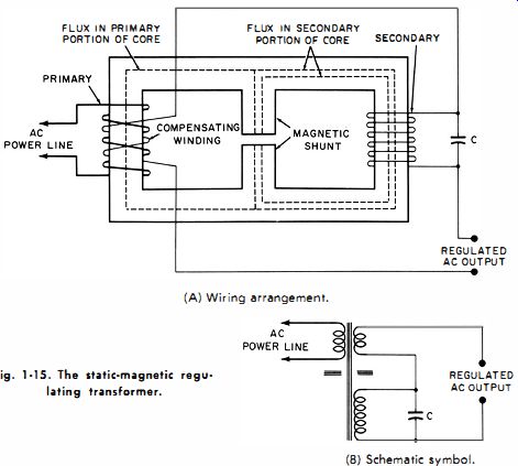
Fig. 1-15. The static magnetic regulating transformer. REGULATED AC OUTPUT
REGULATED AC OUTPUT (B) Schematic symbol.
MAGNETIZING FORCE (AMPERE TURNS)
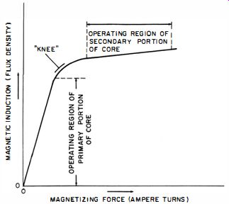
Fig. 1-16. Curve showing operating regions of primary and secondary core
sections in a static magnetic regulating transformer.
Pictorial and schematic diagrams of the basic constant voltage (also called static magnetic regulating) transformer are shown in Figs. 1-15A and B, respectively. This transformer differs from conventional power types in that a magnetic shunt is incorporated in the core geometry and a capacitor is connected across the secondary. These two features provide the common objective of causing more flux to circulate in the secondary portion of the core structure than in the primary portion. The capacitor consumes a large reactive current, and the resultant ampere-turns in the secondary winding produces a high flux. Because of the magnetic shunt, much of this flux is retained in the secondary portion of the core. The magnetic shunt functions as a magnetic isolator, to reduce the coupling between the primary and secondary windings. The significant feature is that the primary magnetic circuit operates below the "knee" of the core magnetization curve, whereas the secondary magnetic circuit operates above the knee-that is, in the magnetic saturation region. See Fig. 1-16. A change in the AC line voltage impressed across the primary winding will accordingly produce a proportionate change in flux in the primary portion of the core structure. Because of magnetic saturation, however, the accompanying flux change in the secondary portion of the core structure will be relatively small. The change in induced voltage appearing across the secondary winding will therefore be proportionately smaller than the change in voltage across the primary. Thus, this type of transformer regulates its own secondary voltage. A further refinement consists of a so-called compensating winding over the primary and connected in series-opposing with the secondary. The voltage change developed across this winding improves the regulation by introducing a small voltage, to compensate for the departure of the saturated region of the magnetization curve from the ideal horizontal slope (that is, from complete saturation ). One of many possible modifications of this arrangement is shown in Fig. 1-17. Here, separate secondary windings are employed for providing capacitor and load currents.
This technique permits electrical and physical utilization of the capacitor without regard to the independent requirements of the load. A similar method, often encountered, involves a single tapped winding.
AC POWER Line, CENTER TAP FOR FULL WAVE RECTIFIER CONNECTION REGULATED AC OUTPUT
(A) Wiring arrangement.
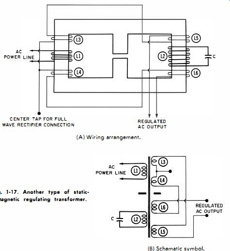
Fig. 1-17. Another type of static· magnetic regulating transformer. (B) Schematic
symbol.
Because the flux in the secondary portion of the core is increased by the capacitor reactive current, the induced voltage in the secondary winding obviously is higher than would be indicated by the numerical ratio of secondary to primary turns. This, however, does not mean that resonance has been established by the capacitor with respect to the inductance of the secondary winding. Resonance is utilized in other types of regulating transformers, but not in the self-regulating transformer described here. The waveshape of the secondary voltage is closer to a square than a sinusoidal wave. This waveshape is actually desirable in many instances, because the rectifying elements are subjected to less peak AC voltage than when a sine wave is being converted to DC.
Transformer Regulation by DC Saturation
Fig. 1-18 depicts a transformer-rectifier arrangement which provides DC voltage regulation as a result of the DC load current flowing through saturable core transformers.
Fig. 1·18. A transformer regulating arrangement using the variable saturation method.
In this circuit, T1 is a conventional power transformer, and its core operates below the knee of its magnetization curve.
Therefore, any induced secondary voltages will be proportionate to the impressed primary voltage. As a result, no voltage or current limiting takes place. However, the cores of transformers T2 and T3 operate in a region of their magnetization curves wherein core permeability can be controlled by the amount of current passing through their DC windings. Accordingly, the inductance of the AC windings of T2 and T3 is a function of the DC load current.
If the load current tends to increase because of a change in line or load conditions, the resultant increase in the core saturation of T2 and T3 will lower the effective inductance of their AC windings. This, in turn, will permit more AC voltage to be impressed across the primary of T3. The tendency for load voltage to fall because of the increased load current will thereby be counteracted. Should the lead current tend to fall, the converse sequence of events will take place and thereby counteract the accompanying tendency of the lead voltage to rise.
Since the secondary windings of T2 and T3 are connected in series opposition, any AC voltages induced in these windings will cancel each other in the DC load circuit. Hence, it follows that saturable transformers T2 and T3 must have identical characteristics ; otherwise, AC ripple will be injected into the load.
General Aspects of VR Tubes
Voltage-regulating tubes are gaseous diodes making use of various mixtures of inert gases such as neon, argon, krypton, and xenon to provide a selection of several ionizing voltages in the normal glow portion of their conduction characteristics. Ordinary neon lamps with two identical pin like electrodes also display constant-voltage characteristics over a portion of their operating curves. These lamps are inferior to VR tubes, however, because a relatively small current will project them into the abnormal glow region, which is unsuitable for voltage stabilization. The unique structure of the elements of a VR tube enable a relatively high current to be consumed before the abnormal-glow mode of operation is reached. As will be shown, the more current a shunt regulating element can consume while still exhibiting the type of current-resistance relationship of Table 1-1, the heavier the load that can be handled.
Fig. 1-19A shows the basic construction of a voltage-regulator tube. Observe that the anode-that is, the positively polarized element-is the much smaller element. The cathode, or negatively polarized element, resembles in both structure and orientation the plate (anode ) of an ordinary electron tube. This fact plus widespread usage of the symbol in Fig. 1-19B-which depicts the anode as the plate-like, or larger, element-naturally leads to confusion. As a consequence, it is not uncommon for technicians or even engineers to sometimes connect VR tubes incorrectly.
(A) Construction. (B) Schematic symbol.
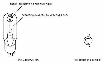
Fig. 1-19. The voltage regulator tube.
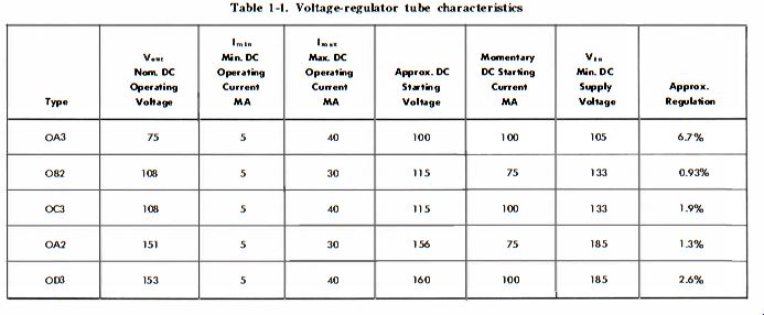
Table 1-1. Voltage-regulator tube characteristics
VR tubes have either internal jumpers or multiple-pin connections, which enable wiring the power-supply circuit in such a manner that no voltage is delivered to the load when the VR tube is not in its socket. This is a protective feature-with no VR tube, the voltage applied to the load will be considerably higher, and there is a possibility of damage. The socket connections of the common VR tubes are shown in Fig. 1-20. When an OA3, OC3, or OD3 is used, it is possible to utilize the internal jumper at pins 3 and 7 (Fig. 1-20A) as a means of breaking the AC supplied to the primary of the power-supply transformer. With the OA2 and OB2 (Fig. 1-20B), multiple-element connections rather than an isolated jumper are provided, so that the positive or negative DC output load is interrupted whenever the tube is removed from its socket.
(A) OA3, OC3, 003. (B) OA2, 062.
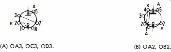
Fig. 1-20. Voltage regulator tube pin connections.
BASIC TYPES OF AUTOMATIC REGULATION
There are a number of ways to classify regulating circuits, and various circuits are employed. For our purpose, we will (at least initially) find it advantageous to assign voltage or current-regulating techniques to one of the two basic family groups.
Open-Loop Regulators
The first of these, the open-loop regulator, utilizes a voltage- or current-sensitive element which automatically changes its internal resistance in such a way that the load voltage (or in some instances, the load current) does not change. Some of the elements which enable this to be accomplished in suitable circuits are gaseous diodes such as VR (voltage-regulator) and corona tubes, reverse-biased junction (zener ) diodes, forward-biased diodes (Stabistors, Varistors, and vacuum diodes), and elements having negative coefficients of resistance with respect to voltage or current (carbon filament lamps, Thyrite cartridges, and Thermistors) . The general circuit used for obtaining stabilized voltage with such elements is depicted in Fig. 1-21A.
(A) Circuit.
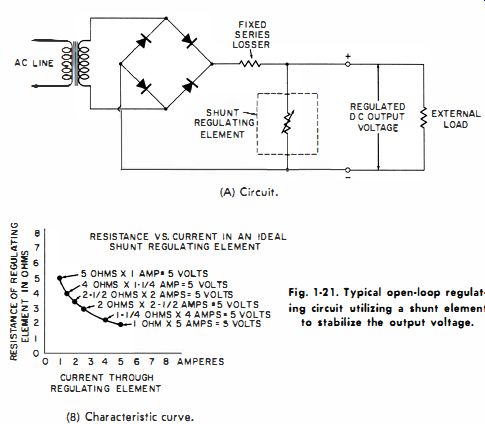
Fig. 1-21. Typical open-loop regulating circuit utilizing a shunt element
to stabilize the output voltage. (B) Characteristic curve.
The curve in Fig. 1-21B, which depicts the behavior of an ideal variable-resistance element, provides considerable insight into the operation of simple open-loop voltage-regulated power supplies. This curve has the interesting property that the product of the two quantities defining any point on the curve is of constant value. Thus, the product of the horizontal units (amperes ) and vertical units (ohms ) is five in this particular example. Specifically, we see that five times one, four times one and one-quarter, two times two and one half, etc., all yield the product five. Inasmuch as this product is derived from multiplying current by resistance, we have the condition wherein 5 volts is maintained for any current on the curve. From this mathematical property, we deduce that an element displaying such a relationship must maintain a constant voltage across itself and therefore in a load connected across it. Gaseous diodes known as VR (voltage regulator) tubes, and reverse-biased silicon junction diodes known as zener or breakdown diodes, closely approach the above described relationship. They are therefore the 'most frequently encountered shunt regulating elements.
Closed-Loop Regulators
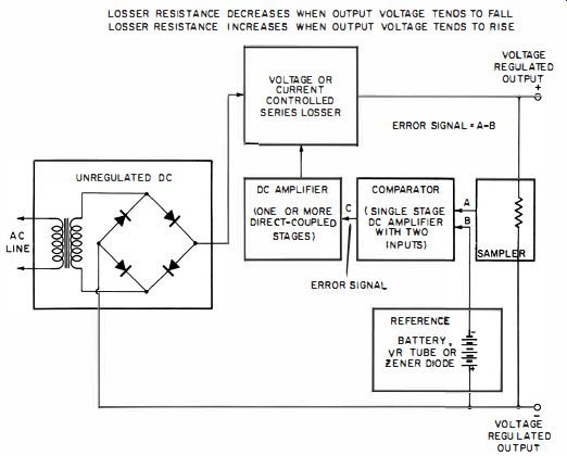
Fig. 1-22. Typical closed-loop arrangement for producing automatic voltage
stabilization.
The other basic regulating technique is represented by the closed-loop, or "error-sensing," circuit. Although such circuits can be subdivided, the essential ingredient of closed loop automatic regulation is control of the output voltage (or current ) in response to an error signal resulting from comparison of a portion of the output with a stable voltage source known as the reference. The reference-voltage source is often a simple open-loop regulator circuit. Thus, a shunt regulator circuit of the type shown in Fig. 1-21, which uses a VR tube or zener diode, is one of the building blocks of the more complex closed-loop regulator.
The closed-loop regulator illustrated in the block diagram of Fig. 1-22 makes use of a series "losser" element, the resistance of which is controlled by the amplified error signal.
Should the DC output voltage tend to rise, the resultant error signal will increase the resistance of the series losser and thereby counteract the voltage rise. The converse events occur if the output voltage tends to fall. In this way, the output voltage is maintained almost constant. The error voltage always tends to extinguish itself by fixing the output voltage at such a value that a sampled portion of it is equal to the reference voltage.
The power demand from the voltage-reference source is generally a small fraction of that which would exist in a shunt-type voltage regulator supplying a similar external load. Consequently, it is relatively easy to provide electrical and thermal operating conditions for the shunt element which optimize its voltage stability and thus enhance the stability of the over-all regulating circuit.
SOME CONSIDERATIONS ABOUT THE RECTIFIER-FILTER SYSTEM
Because of the relative ease with which regulation can be accomplished electronically, the rectifier-filter system often is not given design consideration much beyond that pertaining to production of the nominally required voltage and current. However, it should be appreciated that the ultimate regulation and ripple suppression depends upon both the rectifier-filter system and the regulator. Fig. 1-23. Graph showing poor regulation region at low currents with choke input filter.
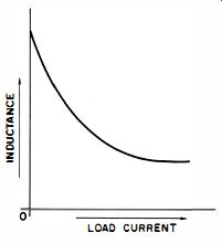
Fig. 1-24. Graph showing inductance versus load current of a swinging choke.
Indeed, when exceedingly good performance is required in these respects, it may be more feasible to enhance the operation by improving the rectifier-filter system rather than by attempting improvements upon the regulator proper. A technique which should not be overlooked is the use of a swinging choke in the power supply. The regulation of a choke input, capacitor output, full-wave power supply is shown in a general way in Fig. 1-23. The major contributor to regulation in region A-B is resistance in the transformer, rectifier bridge, and choke winding. The major contributor to regulation in region B-C is capacitor C1 because L1 does not have any appreciable effect. Note the abrupt change in regulation encountered as load current is decreased from point A (which might correspond to maximum rated current) to point B. This is the consequence of the choke becoming abruptly ineffective when no longer carrying current beyond a critical value. At these low currents the choke no longer prevents the rectifier current pulses from reaching peak and zero values. Therefore, the output capacitor tends to charge to peak voltage ; this manifests itself as a rapid rise in output voltage as load current is decreased to zero.
Higher inductance will cause point A to occur at a lower current. Unfortunately, practical difficulties impose limitations before this design approach can be pursued very far.
A choke with higher inductance also has higher resistance if the core size is maintained. This adversely affects regulation and defeats the basic objective even though the regulating curve can be made somewhat more consistent throughout the load range. Off-setting this by increasing both wire and core size obviously only increases weight and cost. A practical compromise can be affected by taking into account that the flywheel effect of the choke is a function of both inductance and current. This indicates that less inductance will suffice at higher rather than at lower load currents to provide good regulation.
Such reasoning leads to the concept of the so-called swinging choke, one that will swing its inductance in such a way that high inductance will prevail at low load currents and low inductance at higher currents. The low inductance at higher currents is not the desirable operational mode ; rather it constitutes the practical solution in that lower inductances suffice at higher load currents. The important feature is high inductance at low load currents because this permits good regulation over a wide load current range. Such a choke is much smaller and less costly than one designed with a nearly constant value of inductance equal to the highest value displayed by the swinging choke. The change in inductance in the swinging choke is due to magnetic saturation of the core and is the consequence of greatly reducing or eliminating the air gap ordinarily provided in conventional constant inductance chokes. Fig. 1-24 depicts the inductance of a swinging choke as a function of load current.
Even with the use of the swinging choke, an artificial load or bleeder may have to be connected across the output of the power supply in order to prevent voltage rise at load currents approaching zero. However, the power dissipated by such a bleeder will be very much less than the bleeder needed to pacify the low current regulation with a conventional choke. It is desired that bleeder power should be low ; for such power dissipation subtracts from the current available to the load and degrades the efficiency of the system.
Fig. 1-25 illustrates the fact that critical inductance occurs at a lower value with a heavy load than with a light load.
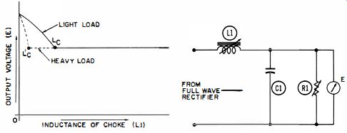
Fig. 1-25. Graph showing the effect of choke inductance on the output voltage
for light or heavy loads.
L1 in the diagram is not a swinging choke, but a manually adjusted variable inductance to make it easier to determine Lc and voltage reduction.
The critical inductance (Ld of a choke is readily calculated in terms of several parameters of the power supply as shown in the following formula :
L_c = R/ p pi f_p (p^2 - 1) henrys
where, R is the combined resistance of the transformer, rectifiers, and load, f is the frequency in cycles per second p is the number of rectifiers firing per input cycle of power line (p equals 2 in single-phase full-wave and bridge rectifier currents ). (With semiconductor rectifiers, rectifier resistance can generally be neglected.) In the common situation where f corresponds to 60-hz AC source and where full wave, single phase rectification is used, this formula reduces to :
Lc = R / 1130 henrys
In actual practice it is always wise to design in the direction of greater inductance ; often circumstances permit a minimum inductance several times greater than Lc_. Such excessive inductance is not wasted, but confers greater attenuation of ripple.
A swinging choke is not useful for half wave rectification because infinite inductance is required to achieve L_c for any load current. Half-wave rectification has inherently poor regulation and thereby requires correspondingly better stabilizing performance from the regulator. Its use is limited to high voltage and/or low current systems, or where the specifications are not demanding.
For reasons of economy, the choke is generally less critically chosen in terms of its inductance. Thereafter, filtering action is most cheaply acquired by using the output capacitor C1. Size and cost become prohibitive here too. At this point, the voltage regulator contributes electronic filtering equivalent to the effect of the impractical size of the chokes and capacitors. However, the initial filtering must be provided by the rectifier-filter system, otherwise, the amplitude of the ripple impressed upon the voltage regulator will carry it beyond its operating range. In such a case, the regulator can neither suppress ripple nor regulate effectively.
When a single output capacitor is used, with or without a series resistance, a brute force approach is generally employed in that the capacitor is made very large. This has become feasible through the availability of relatively small and inexpensive electrolytic capacitors. Because of the high capacitance which can be so used and because of the low-voltage drop in semi-conductor rectifiers, the regulation provided by such a technique is adequate for many practical purposes. It is often necessary to include a small resistance in series with the rectifier output in order to protect the rectifiers from the current surge when the capacitor is initially charged.