AMAZON multi-meters discounts AMAZON oscilloscope discounts
GENERAL CONSIDERATIONS
Most non-feedback, or open-loop, regulating circuits are shunt-type voltage stabilizers. Generally, a gaseous diode or a semiconductor (zener) diode is utilized as the shunt element. Additionally, a series element comprising a fixed resistance appears in these circuits. The two most common shunt-type voltage-regulating circuits are shown in Fig. 2-1 . They can be briefly described as variable voltage dividers in which the shunt arm automatically adjusts its resistance to maintain a constant voltage across itself and the load. Although this simple description is entirely valid, we will gain even more insight into open-loop regulation by investigating this principle in detail.
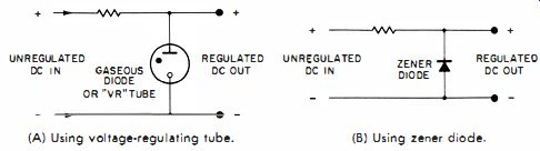
(A) Using voltage regulating tube. (b) Using zener diode. Fig. 2-1. Shunt type
voltage regulator circuits.
The ideal shunt regulating element is one which changes its internal resistance in such a way that the current flowing through it does not change the voltage across it. In Fig. 2-2A is depicted a resistance-versus-current curve which illustrates the basic concept of such an element. Note that the application of the Ohm's-law relationship for voltage, E = I x R, always yields the same voltage, no matter what current is selected. For example, the product of 2 milliamperes and 50K ohms, 10 milliamperes and 10K ohms, 4 milliamperes and the corresponding 25K ohms, etc., is always 100 volts. The voltage constancy despite current change is shown in Fig. 2-2B. In a very true sense, the shunt regulation element is a current-sensitive nonlinear resistance which is inversely proportional to the current flowing through it.
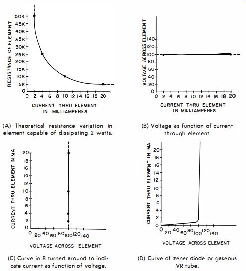
(A) Theoretical resistance variation in element capable of dissipating 2
watts. (B) Voltage as function of current through element . (C) Curve in
B turned around to indicate current as function of voltage. (D) Curve of
zener diode or gaseous VR tube.
Fig. 2-2. Characteristics of a 100·volt shunt regulating element.
Mathematically, such an element would be defined as conforming to the equation :
R = ? I
where, R is the resistance of the element, I is the current flowing through the element, k is a proportionality factor numerically equal to the voltage developed across the element.
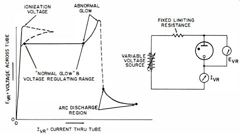
Fig. 2-3. The voltage current characteristics of a gaseous VR tube.
Our equation can be transformed into R = E / I, which to all appearances is one of the Ohm's-law derivatives. However, voltage E in this application is fixed, thereby forcing resistance R to become a function solely of current I. As a result of supplying current to such a shunt element, its behavior-from the viewpoint of the external load-is suggestive of a battery with perfect (zero) regulation. Fig. 2-3 shows the voltage-current characteristic of a VR tube.
The normal glow region has the constant voltage previously demonstrated with idealized shunt regulating elements.
The Need for Series Limiting Resistance
The series element provides a function beyond acting as the fixed section of a variable voltage divider. Fig. 2-2C is a duplication of Fig. 2-2B, but with the axis of the graph restated. Current through the shunt element is now shown as a function of the voltage impressed across the element.
We see that for less than 100 volts, the current is zero. At 100 volts, the current flow theoretically is infinite for our ideal element. In a practical element, the current flow is still extremely large-many tens or hundreds times more than the device can withstand. In other words, an element of this type tends to be self-destructive-the flow of current raises the temperature, lowering the resistance and enabling still more current to flow. A cumulative cause-and-effect relationship would lead to a catastrophic thermal runaway if the current flow were not limited somehow. Fortunately, the series element can be designed to have a resistance which limits the current through the shunt regulating element to values which are simultaneously safe and within the proper region of the characteristics, insofar as voltage stabilization is concerned.
Another Effect of Series Limiting Resistance
An immediate consequence of series resistance is that the input voltage must be higher than the stabilized output voltage. The current flowing through the series element divides between the shunt element and external load. The voltage drop due to this total current flowing through the series element is deprived from the shunt element and load. If this voltage drop is excessive, the shunt element will not receive enough voltage to operate within its voltage-stabilizing region. Although it is convenient to speak of "current-actuated" devices such as transistors, electromagnetic solenoids, etc., we can thereby find ourselves at odds with the physical facts of electricity. Whatever occurs in these devices is always primarily due to the application of a voltage ; i. e., current flow is caused by electrical pressure. This is true even in a series circuit, wherein we say that the "voltage drop across such and such a resistance is 'due' to such and such a current flowing through it," but it is truer to say that whatever current flows through the resistance is due to the voltage impressed across it. Thus, lest we misconstrue the implication of Fig. 2-2A, we must realize that this characteristic exists only if 100 volts can be impressed across the element.
In Fig. 2-2C we therefore see that the device would be inactive unless a minimum of 100 volts were available.
Unfortunately the accompanying voltage drop, as the load current flows through the series element, ultimately deprives the shunt regulating element of its operating voltage as the load is made heavier. The series element thus establishes the upper limit to the amount of current the load may consume ; once this limit is exceeded, the shunt regulating element can no longer stabilize the load voltage. Fig. 2-4 depicts the basic equation relating the relevant parameters of a VR-tube shunt regulating circuit.
VOLTAGE STABILIZATION IN OPEN-LOOP CIRCUITS
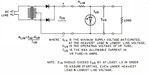
Fig. 2-4. Calculating the series limiting resistance of a shunt regulating
circuit.
Voltage Stabilization with Fixed Input and Varying Load
Figs. 2-5, 2-6, and 2-7 show how voltages and currents change in order to permit the VR tube to maintain a constant output voltage under the condition of fixed input voltage and varying load current. Voltage stabilization is maintained as long as the VR tube is supplied with current within the flat (horizontal ) portion of its operating characteristics (Fig. 2-5) . It is interesting to observe that current stabilization also exists in this circuit (Fig. 2-6) . I_A, the total current consumed from the source of input voltage, remains constant despite variations in the load current (within the regulating range of the VR tube) . There is another quantity which remains fixed as long as output-voltage stabilization exists ; this is the equivalent resistance of the load and VR tube in parallel. It is this quantity which is responsible for the constancy of output voltage and supply current. That this is so follows from the basic voltage-divider configuration of the regulator circuit (Fig. 2-7) . Table 2-1 shows the relationship between various values of load resistance and currents within the circuit.
Voltage Stabilization with Varying Input Voltage and Fixed Load
When the load current is maintained constant but the input voltage is permitted to vary, the circuit action is somewhat different from that described for the converse set of conditions. Fig. 2-8 shows the effects of variations in the source voltage on the output voltage. From Table 2-2 and Fig. 2-9 we now see that the output-voltage stabilization is accompanied by a constant load current I_L. The variation in VR tube-current consumption is exactly what is required to enable the shunt arm (load and VR tube ) to relate to the series-dropping resistance in such a way that a constant load voltage is maintained in the face of a changing input voltage.
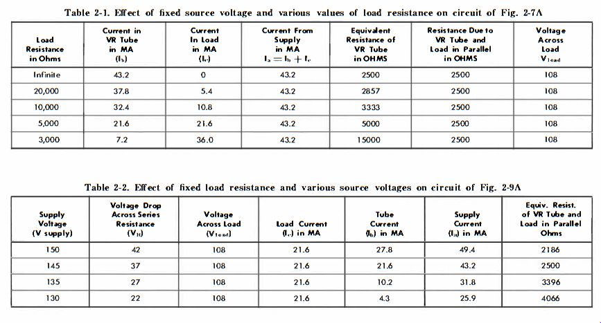
Table 2-1. Effect of fixed source voltage and various values of load resistance
on circuit of Fig. 2-7 A

Table 2-2. Effect of fixed load resistance and various source voltages on
circuit of Fig. 2-9A
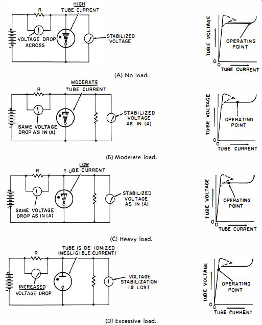
(A) No load. -- (B) Moderate load. - (D) Excessive load.
Fig. 2-5. Effect of various loads on regulator circuit voltages.
Variations in Both Input Voltage and Load
In general usage, the input voltage and the load both vary.
As a consequence, both circuit actions previously described take place simultaneously. Despite this more complex operation, the load voltage is stabilized, for each of the described actions responds uniquely to the conditions responsible for it.
The load current and the voltage drop across the series limiting resistance will no longer be constant, as they were in the two experiments. Nevertheless, the resistance of the VR tube still adjusts to values which always result in a constant output voltage.
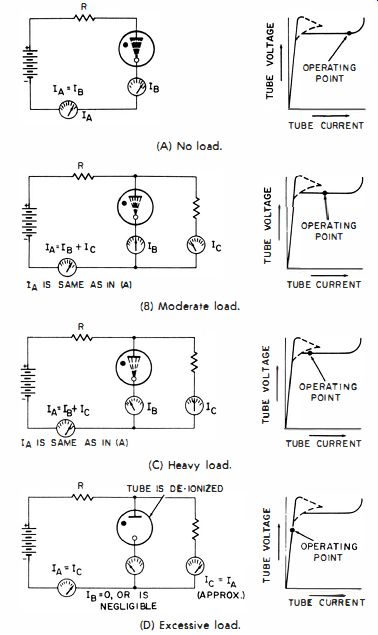
(A) No load. (B) Moderate load. (C) Heavy load. (D) Excessive load.
Fig. 2-6. Effects of various loads on regulator circuit currents.
(A) Circuit. (B) Current resistance curve.
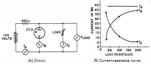
Fig. 2-7. Regulator circuit action when source voltage is fixed and load
is variable.
(A) Moderate DC voltage variations. (B) DC voltage too high. (C) DC voltage too low.
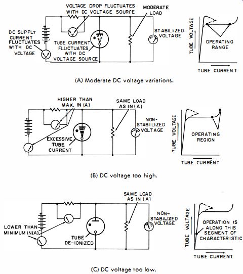
Fig. 2-8. Effects of source voltage variations on voltage-regulator circuit.
THE VR TUBE AND ITS APPLICATIONS
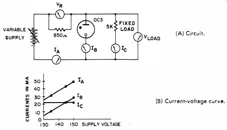
(A) Circuit. (B) Current voltage curve.
Fig. 2-9. Regulator circuit action when load is fixed and the source voltage is variable.
Load Capabilities of VR Tubes
Most VR tubes are rated at currents between 5 and 40 milliamperes. It is an interesting fact that, as long as the VR tube current is maintained within this range, no limitation is imposed on the current consumed by the load.
Certain practical matters make it difficult or undesirable to attempt voltage stabilization for high-current loads, however. A heavy current load necessitates a relatively low series dropping resistance; otherwise, the DC supply voltage from the rectifier would have to be inordinately high. If such a load became disconnected from the output terminals, the VR tube would be damaged or destroyed by the heavy current which would then flow through it. Allowing for this possibility, however, there is no reason why the VR tube could not stabilize the voltage across a load drawing much more current than the tube itself. For example, if the intention is to stabilize against line-voltage fluctuations and it is ascertained that the load, although heavy, is relatively constant and always present, a VR tube can be used for higher load currents than would be permissible with a varying load.
Ignition Voltage for Gaseous Tubes
Gaseous diodes such as VR tubes require higher than the operating potential to start ionization of the gas. Now another requirement is imposed on the rectifier or unregulated DC supply-the minimum voltage available under the worst conditions must be sufficient to fire the tube. Otherwise, tube conduction will be negligible and voltage stabilizing action will not be attained. "Worst conditions" generally involves the simultaneous occurrence of full load and low line voltage.
Sometimes other conditions aggravate the problem of starting. Experiments have shown that a gaseous diode with a normal glow voltage of approximately 70 volts requires over 200 volts to fire it when placed under refrigeration and in the absence of light. The energy of light photons is imparted to the gas molecules and also produces photoelectric emission from the electrodes. As a consequence, it is good practice to provide a suitable margin of surplus starting voltage-particularly if separation is to take place in total darkness.
Under ordinary conditions (at or above room temperature and with even the small amount of light available from the tube filaments ), the starting voltage of VR tubes is generally from 8 to 20 volts higher than the operating voltage.
Some tubes now contain a radioactive isotope, which brings about reliable starting at lower potentials.
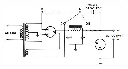
Fig. 2-10. Methods of connecting a small capacitor to aid in initial ionization
of VR tube.
It is possible to initiate ionization with a lower DC supply voltage if a small capacitor is connected across the series dropping resistor. The capacitor bypasses a portion of the otherwise undesirable ripple component around the resistor, making it available as additional starting potential. If the rectifier output passes through a filter prior to being impressed across the VR tube, the bypass capacitor should then be connected between the VR-tube anode and the positive output terminal of the rectifier, or to one of the high-voltage terminals of the power transformer. See Fig. 2-10. Here, lead A of the capacitor can be connected to point B, C, or D. The last is the most effective of the three. Sometimes the voltage stabilizing action or the filtering effect of a VR tube is desired for a circuit not previously designed to furnish the required starting voltage. If sharp pulses of sufficient amplitude, or audio or radio frequencies of suitable voltage level, are available elsewhere in the equipment, the introduction of such energy through a small capacitor connected to the anode of the VR tube can facilitate firing. Sometimes, better results are obtained by connecting the small capacitor to one of the "blank" pins of the VR tube. The electrified point of the pin within the tube then becomes a copious producer of ions.
Combinations of VR Tubes Parallel-Connected VR Tubes--It is possible to obtain certain special results by appropriate combinations of VR tubes.
CURRENT SHARING RESISTANCE
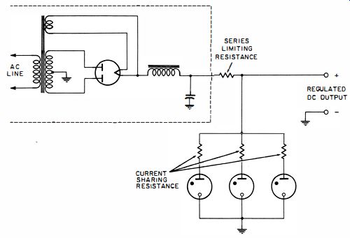
Fig. 2-11. Method of connecting VR tubes in parallel.
REGULATED DC OUTPUT
One quite likely to come to mind would be parallel operation in order to increase the current-handling capability of the load. However, if two or more VR tubes are simply paralleled, it is highly probable that only one will ignite--the resultant lowering of output voltage by the ionization of one tube will tend to prevent the others from starting. This is undesirable in another respect. Since the circuit is designed for a high current output, its series limiting resistance would be too low to prevent damage to the tube "lucky" enough to ignite at the expense of the others. Even if two selected tubes were utilized in such a fashion that both were assured sufficient starting potential and current, subsequent operation would tend to be unstable as one tube or the other hogged most of the available operating current. Current sharing can be enforced by means of individual series resistances, as in Fig. 2-11. In this way, parallel operation can be employed to provide a stabilized voltage to heavy loads. However, insertion of the current-sharing resistances will seriously degrade the regulation and dynamic output impedance. Hence, except where poor stabilization is better than none, paralleling of VR tubes in this manner is not recommended.
Series-Connected VR Tubes--VR tubes connected in series constitute a practical circuit configuration with several operational advantages, such as stabilization of higher voltages than can be accomplished with one VR tube alone. Although it is preferable to employ tubes with identical current ratings, any combination of voltage breakdowns may be selected. If one tube has a lower rated maximum current, the series limiting resistance and the input voltage should be so related that this current is never exceeded in any tube.
Another advantage of series-connected VR tubes is the availability of more than one stabilized DC voltage, as shown in Fig. 2-12. VR tubes connected in a series arrangement.
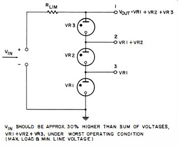
Fig. 2-12. Here we see that, in addition to ordinary VR-tube action, such
an arrangement functions as a voltage divider.
The number of stabilized voltages provided is equal to the number of series-connected VR tubes.
In Fig. 2-12, due consideration should be given to the fact that upper tubes are forced to carry the current consumed by any loads connected to the lower taps. For example, if a load is connected between ground and tap 3, VR2 and VR3 must supply this current, even though the voltage to this load is stabilized by VR1. As a consequence, the allowable load currents available from taps 1 and 2 are lower. Similarly, if taps 2 and 3 are supplying current to loads, the permissible current output from tap 1 is diminished by the sum of the currents supplied by taps 2 and 3.
Cascaded VR Tubes--In Fig. 2-13 we see a cascade, or tandem, arrangement of VR tubes. In this circuit, the VR150 constitutes a stabilized input-voltage source for the operation of the VR75. This technique greatly enhances the stability of the VR75, which is now virtually relieved of the need to regulate with respect to the varying input voltage.
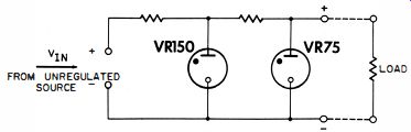
Fig. 2-13. Cascaded VR tubes.
A requirement of this circuit is that the tube receiving its operating power from the unregulated source must have a higher breakdown voltage than the tube which stabilizes the load voltage. Because of the limited number of breakdown voltages available in VR tubes, this arrangement is not as flexible with VR tubes as it is with zener diodes, which may be had in a wide variety of breakdown voltages.
High-Voltage Regulated Supplies Using Corona-Type Tubes
By suitable choice of gas pressure and electrode geometry, a gaseous diode can be designed to display a voltage-regulating region at much lower currents than those required to produce a glow discharge in a conventional VR tube. At the same time, this regulating region can be made to correspond to electrode potentials at least as high as 25 kilovolts. Ionization at these relatively high voltages and low currents is essentially a corona phenomenon. These tubes are known as Corotrons and are manufactured by the Victoreen Instrument Company. The simplest type of regulator circuit is identical in configuration to the conventional VR-tube circuit (Fig. 2-14A) . The same manufacturer also makes high-voltage pentode tubes, for use with the Corotron in closed-loop regulator circuits. A typical circuit of this type is shown in Fig. 2-14B. Observe that a separate voltage amplifier is not employed to boost the level of the error signal before it is applied to the grid of the pentode losser tube. This in itself is not a novel circuitry feature. There is, however, more than initially meets the eye. The voltage drop across R1 (Fig. 2-14B) is a small fraction of the total output voltage. Therefore, the feedback factor is not divided down appreciably by the sampling network (R1 and the Corotron). This fact, in conjunction with the high voltage gain of the pentode, results in a loop gain as high as might be obtained in conventional lower-voltage regulators utilizing one or two stages of DC voltage amplification prior to the losser element.
By dispensing with the cascaded DC amplifiers, this circuit achieves low dynamic impedance with very little of the ordinarily accompanying drift.

(A) Basic circuit. (B) High-voltage pentode used in conjunction with corona
tube.
Fig. 2-14. High-voltage corona-tube regulator circuits.
Disadvantages of Gaseous Diode Voltage Regulators
Before the advent of the semiconductor reference element (zener diode) , it would have served no useful purpose to cite the shortcomings of the gaseous VR tube, for nothing better was available. Since this is no longer true, it should prove instructive to summarize the undesirable characteristics of the VR tube:
1. The requirement of a higher-than-operate starting voltage.
2. The possibility of spurious signal generation (relaxation oscillations, ionic or molecular oscillations, and "hash" or noise voltage ).
3. The availability of the device in only a few operating voltages.
4. Limited life span.
5. Unpredictable and erratic tendencies with regard to both the starting and the operating voltages.