There are several factors which contribute to the slow but eventual deterioration of all vacuum tubes. In separating them into specific topics for discussion, we must keep in mind that these factors are often interrelated.
In fact, they seldom occur separately. However, one is usually more pronounced than the others, and therefore the prime cause of failure can be attributed to that specific factor-even though the others may have contributed their share in bringing tube life to an end.
GAS
High on the list of phenomena which contribute to tube failures, and which are of an evolutionary nature, is gas.
The presence of gas in a tube does not necessarily mean it has reached the end of its useful life, or its life expectancy will be less than some other tube. This is one of the common assumptions frequently made by those who presume to "test" tubes in the field.
To illustrate the point, tubes have been manufactured without getters. Using conventional "grid testers," these tubes were very "gassy." Yet, when placed in controlled life tests and compared with similar tubes that had getters but showed little or no gas indication, these so-called "gassy" tubes outlived and outperformed their more normal mates.
Why should this be so? The answer is not well under stood, even by tube engineers. It is apparent that there can be harmless gas conditions as well as those that are harmful. It is obvious that all gases are not harmful to tube life, because some tubes are made with certain gases in them, gases that are essential to their proper functioning. These tubes live long, trouble-free lives when properly used.
Without attempting to identify the specific forms of harmful gassing, we will discuss those conditions which, as learned through experience, leads to relatively early gas evolution and shortened tube life. Elevated heater temperatures, brought on by high heater voltages, have long been looked upon as a prime cause of premature gas sing. This may be the result of the liberation of water vapor bound in the heater insulation, or it may only be a contributory cause since raising the heater temperature increases the temperature of every other part of the tube.
This will cause gas evolution from other areas, as will be pointed out shortly.
High cathode current density is known to contribute to early gassing. Possibly, this is because the higher current increases the formation of ions, thereby making the measurement of the gas easier. Or it may be that the heavier electron stream produces increased cathode temperature, especially in localized areas, and thereby releases more gas into the tube.
Operation of screen grids and plates at elevated temperatures has long been associated with early gas formation. It is possible that this is caused by the evaporation of some of the relatively volatile materials used in coating these elements. In order to help reduce the temperature of screens and plates, they are frequently coated with such substances as carbon, thereby increasing their capacity to radiate heat. However, these same substances can be very harmful to tube life if they become volatilized due to excessive heat.
GETTERS
This brings to mind the question of why certain tubes power tubes used in some of the older RF applications specifically-consistently ran with red plates. Why didn't these tubes gas up immediately? Well, the answer is that there are a few tubes which are designed to run with red hot plates, and running them this way actually extends their life. This is because these tubes contain a substance (carbon or zirconium) for combating the evolution of gas, and this substance works most effectively when it is hot.
When plates are made of carbon, or coated with zirconium, they will absorb gases which are evolved by other parts of the tube and will entrap them in a chemically inert state, provided they are run hot enough. However, this is not true of most small tubes. In fact, precisely the opposite effect takes place in tubes having the characteristic silvering or blackening on their sides or tops.
These "getters," as they are called, are patches of evaporated metal which have adhered to the inside of the glass.
Their purpose is to absorb gases which evolve during the life of the tube. They work best when warmed by the normal bulb temperature, but can be evaporated by excessive bulb temperature. Thus, not only will they add their own vapors to the gas content of the tube, but in so doing, they will release any gases which they may have entrapped.
Getters show certain physical changes when they are worn out, or when they have been subjected to excessive temperatures. A tube which has an air leak will have a milky white getter. This is obviously a bad tube. Tubes with getters which are thin, and which are discolored or "washed out" at the edges, have undoubtedly seen excessively high temperatures and are a poor risk, even though they may be working quite satisfactorily at the time.
Even a few new tubes may show small, poorly defined getters. These may indicate shelf deterioration and may represent poor risks in critical sockets.
While on the subject of new tubes, it should be pointed out that some increase in gas content can be expected in tubes which have not been operated for long periods of time, whether new or old. Performing gas tests on such tubes without adequate preheating may lead to false conclusions. After a short period of operation, the apparent gassy tube may clean up completely, due to getter action becoming more active when heated.
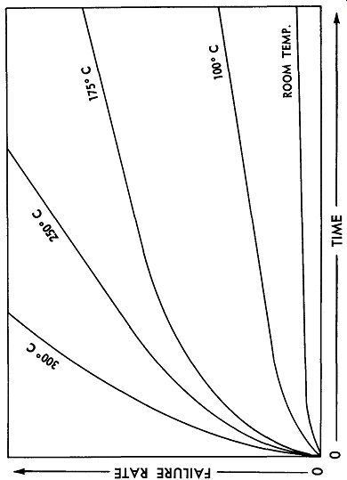
Fig. 2-1. Ambient bulb temperature has a marked effect on tube life.
Perhaps the most effective means for preventing pre mature gassing is the control of bulb temperature. This subject is so important that it will be treated in much greater detail in a subsequent section. It is sufficient to point out here, however, that all the heat generated within the tube must find a way out, or the tube and its elements may melt. In fact, in certain extreme instances of poor heat control, bulbs have been known to melt and collapse right around the tube structures. Some of these tubes were still working when removed from their sockets! There are only three means by which the internal heat of the tube can get out--by metallic conduction through the pins, by conduction and convection to and from the glass, and by radiation through the glass. Very little heat escapes through the pins of most tubes. They are too small and the route is too long. Direct radiation accounts for some heat loss; however, much of this energy is converted to low frequency heat in passing through the glass, resulting in an increase of the bulb temperature itself. About the only way to cool the bulb is to circulate cool air past it rapidly, so that the excess heat is removed faster than it builds up. The presence of close-fitting shields or en closed compartments or containers often makes this very difficult to accomplish. Nevertheless, the successful accomplishment of this objective can result in amazing reductions in over-all failure rates. Controlled tests have shown a ten-to-one increase in failures versus hours of use when bulb temperatures were raised from room temperature to an ambient temperature of 300°C. (Fig. 2-1). Even an increase of as little as 100° in the ambient temperature can increase failure rates as much as three-to one.
SPURIOUS EMISSIONS
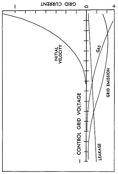
Fig. 2-2. Curves showing changes in the four types of grid current with
different values of grid voltage.
In any discussion of gas in vacuum tubes, it soon be comes apparent that what is most often referred to as "gas" i8' more properly described by the term "grid current." All grid current is not gas current. In fact, gas is only one of four or more currents which are commonly associated with the grid of vacuum tubes (Fig. 2-2). While true gas current may be regarded as a defect, or a sign of degeneration, certain other grid currents are normal and their reduction or absence may actually indicate deterioration rather than improvement. Others, while not desirable in all cases, are actually beneficial in some circumstances. Some grid currents build up with time others decrease. The measurement and isolation of each, individually, is both difficult and inconclusive. There is no simple grid-current test that means the same thing every time. Not only do these currents vary in magnitude, but also in polarity and effective impedance.
"Initial velocity" current, sometimes improperly called "contact potential," results when some electrons leave the cathode solely due to the temperature at its surface. These electrons have enough velocity to keep them going until they hit the grid. If a resistor is placed between the grid and cathode, a current will flow causing the grid end to become negative. This current usually varies directly with cathode temperature. Initial velocity current changes with age and usually decreases as cathode activity declines. This current is used in simple biasing circuits such as those found in many high-gain audio stages where a resistor of several megohms appears between the grid and cathode.
It is also used in some cascode RF-amplifier circuits to provide the bias for the second section. If this current is absent, these circuits will not function properly. In the case of the cascode tube, the absence of initial velocity current will lead to early tube failures. Grid-current testers which reject any tube having grid current will con tribute to early tube failures in front ends for this reason as well as others. This topic will be enlarged upon when we discuss tuner tube problems in a later section.
True gas current is an ionic current which will usually be present only during plate-current conduction. If a tube is measured when in a cutoff condition, or with no plate current flowing, the positive grid current which may be read will not be gas current. Gas current consists of positive ions, and hence, is opposed to initial velocity current.
In fact, they may cancel each other and the result will be a reading of "no current" in the grid circuit. This does not mean the grid has infinite impedance; in fact, its impedance might be much lower than a tube which showed considerable grid current. Ionic gas current usually increases with age and conduction current, disappearing when conduction is stopped.
The electron flow away from the grid, due to excessive grid temperatures which cause the grid to become an emitting surface, is what is called "primary" grid emission. Grid emission is rarely encountered in tubes whose grids do not swing positive. This rules out most receiving tubes. Grid emission will not be present unless the grid is allowed to become quite hot. Thus, any test for grid emission which does not operate the tube at full dissipation is probably not reading grid emission. It is an unstable characteristic and may increase or decrease with life. It may be caused by excessive cathode temperatures which boil off emissive materials onto the grid. Reducing heater voltage will often slow down or stop grid emission if it has not already progressed too far. Decreasing grid current in those applications where grid current is sup posed to flow will also reduce grid emission. Grid emission is a current which causes the grid to develop a positive voltage across a resistor connected between it and the cathode. Since grid emission is almost directly a function of grid temperature, and a reduction of bias usually results in increased dissipation with a consequent further increase in grid temperature, its presence will usually lead to destructive "run-away" unless grid resistors are maintained fairly low. In fact, that is about the best protection the user can employ against any form of shifting grid current; i.e., to use the lowest value of grid resistor practical and to avoid the use of fixed bias supplies whenever possible.
There are several other forms of spurious emission in vacuum tubes. In high-power tubes (horizontal-deflection amplifiers, for example), screen grid emission is not un common. This results from excessive screen dissipation, usually caused by improper setting of the drive control.
Observing manufacturers' recommendations with regard to maximum cathode currents will do much to eliminate this form of trouble. This will be covered in more detail in a later section.
Screen emission can result in another form of grid emission-secondary grid emission. This occurs when the plate voltage goes negative and the screen-emitted electrons are driven back at high velocity toward the cathode.
Many of them strike the grid where they knock off additional electrons with each impact. The effect is much like that of primary grid emission, except that it may result in even higher grid currents. This is frequently the case when a horizontal-amplifier tube all but stops functioning after several hours of satisfactory use. If allowed to cool sufficiently, it may start up again and behave quite normally for several more hours, only to collapse again with very little warning. If the set is removed from the cabinet and allowed to operate on the bench where the ventilation is better, it may run indefinitely with the same tube in the socket and no sign of a failure. In this we see again the close connection between bulb temperature, proper ventilation, and tube life.
INTER-ELECTRODE LEAKAGE
The individual elements of a vacuum tube are supported and insulated from each other by one of several materials, of which mica is by far the most common. Mica is a mineral occurring in nature in chunks which are mined, cut into rectangular sections, and later split into sheets. The mica sections used in making tubes are then punched from these sheets.
Natural mica has very excellent insulating properties and can be subjected to very high temperatures without break-down. However, in a vacuum tube, there are materials operating at temperatures near their vapor point.
When these metallic vapors settle on the smooth mica surfaces, they produce a gradually decreasing resistance. To slow down this process, micas are coated with a finely divided substance that tends to break up the metallic vapor films. This results in a situation similar to that which occurs when raindrops fall on a clean automobile hood. Many small droplets appear first, widely separated from each other. As more rain falls, the drops become larger until finally one or two merge and then suddenly a whole series of drops become connected as a small stream of water starts running down the slope of the hood. In the vacuum tube, that small stream is one leak age path. The more it forms, the lower the resistance between elements becomes.
The nature of these leakage paths is such that their resistance tends to change with the applied voltage. What may be a very high resistance initially, becomes a much lower resistance when higher and higher voltages are applied across it. That is why it is possible for many of the so-called "short testers" to actually produce shorts where none existed before. This will be covered in more detail in the section on testing tubes.
Insulation leakage caused by the deposition of metal films proceeds at a uniform rate in all tubes; however, it is greatly accelerated by such excesses as high heater voltages and high electrode dissipation. Cooling bulbs will often retard its development considerably because the vapors will usually deposit on the coolest surface.
If this is the glass envelope, they will generally cause less harm there than on the micas. As insulation resistance begins to decrease, it will progress very rapidly even though its initial build-up may be extremely slow. This is because even though the release of metallic vapors is more or less constant, the early effect is to produce islands of metallic film which are not connected with one another.
As the islands become larger, the chances of their remaining isolated gets smaller, until finally, many islands connect and form multiple leakage paths almost simultaneously.
There is a special case of leakage that was touched upon in the previous section, but which can be enlarged upon now that we are looking at the causes of progressive deterioration. This is the leakage between heater and cathode (Fig. 2-3). In the previous section, it was pointed out that destructive leakage developed much faster if there was a high potential between the heater and cathode. We now want to point out some of the unique characteristics of this leakage phenomenon.
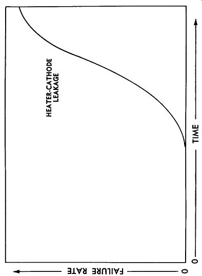
Fig. 2-3. Heater-to-cathode leakage increases sharply with age.
It has been demonstrated that the development of leak age is much slower when the heater is positive, rather than negative, with respect to the cathode. Apparently, there is a semiconductor characteristic to this insulation material, causing it to behave very much like a rather in efficient diode. This is borne out when an AC potential is applied between the heater and cathode. Rectification is quite nonlinear, resulting in high-order harmonics of the fundamental appearing on the cathode, if there is considerable resistance in series to ground. Leakage testers which use rectified AC voltage as the test potential will show very little correlation with equipment usage when attempting to measure this characteristic. That is why the neon-bulb leakage testers in the ordinary field tube testers provide little evidence of the true insulation conditions of the heater. There are tests for this condition which do correlate, but they will be discussed in more detail later.
INTERFACE RESISTANCE
Ordinary receiving tubes, as they are so often miscalled these days, were designed to operate in circuits where normal amounts of cathode current are drawn, more or less continuously, over long periods of time. Modern applications have placed many of these tubes in circuits where current is drawn only in pulses, and then only for relatively short and infrequent intervals. The pulse current may be hundreds of milliamperes; yet, the average or RMS current may be only microamperes. Under these conditions, tubes have been known to lose up to 50 percent of their transconductance in only a few hundred hours. A typical application is a blocking oscillator, and the symptoms would be failure to run at the correct frequency, or failure to sync.
When measured, these tubes appear to have low trans conductance; yet, on further analysis, it can be shown that this is not the case because they may be restored almost to normal by merely raising their heater voltage. This condition is what is known as cathode interface resistance, or "sleeping sickness." It comes about after long periods of operation at very low plate current. It is known to be greatly accelerated by raising filament voltages.
The exact mechanism by which the formation of cathode interface takes place is still a matter of conjecture among tube engineers; however, some relatively plausible explanations can be offered. The phenomenon appears to be a resistance in series with the cathode, shunted by a small capacitance. It is this resistance which causes the apparent loss in transconductance, as well as a loss of circuit gain. Raising heater voltage momentarily appears to reduce this resistance, while lowering heater voltage greatly increases it. This, of course, is after the interface has already developed. This acts almost as though the cathode coating itself were separated from the nickel cathode sleeve, and that heating and cooling it caused alternate expansion with its better contact, and contraction with its poorer contact resistance. This may not be exact, but it offers a satisfactory mental image of the phenomenon.
Computer tubes and others used in similar applications requiring long periods of standby are especially subjected to this form of deterioration. There is no simple cure for it, but there are at least two ways to reduce its rate of development. The first is to operate heaters at below ratings whenever possible, and the second is to permit tubes on standby to draw some plate current. Where neither of these expedients is practical, it is possible to purchase tubes having special cathodes that are nearly immune to this phenomenon. These are usually tubes of the "premium" variety which have special tests or controls added to make them more reliable. Freedom from interface formation is generally one of them.
CATHODE DEPLETION
If a tube survives all the many pitfalls we have been describing, and operates for many thousands of hours, it will in time succumb to some form of cathode deterioration. This deterioration is generally described as loss of emission, and is the characteristic most commonly associated with tube failure in most users' minds. In reality, however, it is a fairly rare development.
Modern oxide-coated cathodes have such adequate sup plies of emission built into them that by the time a tube actually has lost emission, it is a pretty dead tube by a number of other standards. Almost all service testers measure emission in one way or another. Even the so called mutual conductance checkers are more sensitive to emission current than they are to transconductance. We will see why this is true in the section on tube testing and tube testers.
Theoretically, a normal cathode should have tens of thousands of hours of emission capabilities. This is frequently not the case because of some of the things which happen to cathodes as a result of other phenomena within the tube. Most of these have been mentioned already under separate headings. We will now try to bring them all together and see how they affect the cathode itself.
A cathode may lose emission very rapidly by having much of its active surface removed by successive arcs.
When this happens, the vaporized coating material will usually generate so much gas that the entire interior of the tube will be filled with a blue glow, a very obvious sign that the tube has reached the end of its useful life.
Some gases, especially those liberated from excessively hot glass envelopes, have the capacity to combine with the emitters in the cathode coating, rendering them inert.
This chemical poisoning of the cathode can also occur when certain metals used to protect the grids, to prevent them from emitting, become vaporized and combine with the cathode surface metals. These inert substances, such as gold or carbon, then cause the cathode itself to become relatively inert.
In the normal cathode, there is an electrolytic migration of electrons from lower atomic layers to those on the surface, and thence to the space charge surrounding the cathode. When excessive peak currents are drawn from the space charge and it becomes depleted, the electrostatic fields act directly upon the cathode itself and cause deep layer eruptions. The electrons driven upwards under these circumstances are not replaced from below, and a depletion layer develops. As a result, peak emission is permanently reduced.
Reactivation
From the earliest days of vacuum tubes, some form of cathode reactivation has been practiced. It is still very much with us today in the form of picture tube boosters and re-activators. Many cathodes suffering from reduced emission can be restored to normal emission for at least a short while, and in some instances, for quite a long time.
Reactivation methods are all based on the two phenomena discussed in the foregoing paragraphs. The most common one is to simply raise the heater voltage about ten percent. This will frequently restore the cathode to more or less normal activity, provided the cause of failure is one associated with interface resistance, or the formation of a depletion layer. Of course, this method has the disadvantage of hastening the day when the heater will burn out or the insulation between it and the cathode will break down because, as we have shown, these are greatly accelerated by elevated heater voltages.
The second method is to raise the heater voltage about fifty percent for a few minutes while drawing about twice the rated cathode current through a suitable load. The success or failure of this method depends upon whether or not the heater burns out during the process-if not, on whether the cathode can be reactivated by boiling up new sources of free emitter atoms from deep within the cathode coating. When this method is used, and the immediate results are not disastrous, the benefits that follow are usually fairly stable. Sometimes the life of a tube can be doubled, or even tripled, in this way. It does require some skill and a certain amount affamiliarity with the different tubes and their particular cathodes. It also assumes that the cathode defect is one that will be corrected by such treatment.
In the next section, we will discuss tube defects that are not catastrophic, in that they do not usually occur without warning. Nor are they degenerative, in that they do not usually build up gradually. These are the defective tubes that are apparent almost immediately in some applications. Yet, in some other application, they may be perfectly satisfactory.