TELEVISION
Television is a specialized branch of the radio industry and requires study of the various types of circuits utilized for the production of high voltages and special wave shapes, together with a thorough knowledge of the cathode-ray tube.
Modern television receivers are designed around the cathode-ray tube -- the reason for this being that every circuit contributes ultimately to the operation and control of a cathode-ray, commonly known as an electron beam.
THE CATHODE-RAY TUBE
The cathode-ray tube is essentially a vacuum tube with special design features to produce a narrow beam of electrons accelerated by a large positive potential, and caused to move at a high velocity toward a chemically prepared screen which fluoresces when bombarded by high speed electrons. The beam can be deflected and modulated so easily that it has many properties which are desired in the art of television.
Television requires the use of two distinctly different functional types of cathode ray tubes; namely, the Camera tube which is located in the television studio, and the Picture tube for the reproduction of the transmitted picture at the receiving end.
The Camera tube converts light energy into electrical energy which represents the video signal. This signal from the camera is amplified and used to modulate a carrier wave; then, after transmission and reception, the Picture tube reconverts the video signal back into light energy for viewing. Trans mitted simultaneously with the video signal are blanking and synchronizing pulses which hold the horizontal and vertical scanning circuits in synchronism with the transmitter, to produce 30 frames per second, each frame being made up of 525 horizontal lines, according to present-day standards.
For ease of comprehension in the study of television reception, the receiver is broken down into three major circuit sections which have independent functions. They are as follows:
1. Cathode-ray beam formation and control.
2. Cathode-ray beam deflection systems.
3. Cathode-ray beam modulation and synchronization.
Figure 1 shows this division in block diagram form.
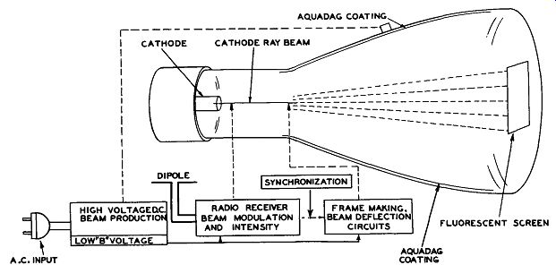
Fig. 1. Radio Plus Video Creates Television.
These three master subjects serve as a guide of what to study, and how to study, and are in the correct sequence to afford the reader a clear understanding of what takes place in a television receiver.
BEAM FORMATION AND CONTROL: Involves the study of high potentials, testing techniques, the cathode-ray tube and electron optics.
BEAM DEFLECTION SYSTEMS: Involves the study of blocking oscillators, free-running multivibrators and wave-shaping circuits.
BEAM MODULATION and SYNCHRONIZATION: Involves the study of high frequency broadband receivers, video detectors, video amplifiers, and D.C. restorers. The reader is advised to thoroughly grasp one subject at a time to prevent confusion and disappointment. The study will not be difficult if this simple rule is followed.
BEAM FORMATION AND CONTROL
Figure 2 shows a simple cathode-ray tube used in early experiments to develop a narrow beam of electrons. Emitted from a hot filament, the electrons proceed forward under the attraction of a positively charged plate. Accelerated by this positive charge, the beam reaches a velocity of many thousand miles per second, depending upon the force of this attraction. The equal negative charges carried by each electron tend to set up a repelling action that causes the emitted beam to widen or scatter. However, the small hole in the center of the anode narrows the beam and permits some of the fast-moving electrons to proceed to the end of the tube without appreciable loss of velocity.
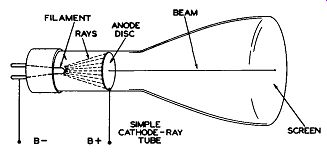
Fig. 2. Formation of a Narrow Beam of Electrons. (Early Experimental Form}
The electrons that make up this narrow beam are traveling too fast for any effective scattering action to take place, thus causing a small illuminated spot to be produced on the fluorescent screen. In the process of narrowing the beam, the electrons that scatter are collected by the positively charged anode causing a current to flow through the "B' supply circuit. This type of cathode-ray tube is very elementary, but serves adequately to facilitate a discussion on the production and formation of a narrow beam of electrons which will strike a fluorescent screen developing a spot of light. The color of the spot depends upon the type of chemical used on the screen.
For further information regarding the chemicals in common use for this purpose, reference should be made to the table which will appear later in the text.
Cathode-ray tubes used in television are fundamentally comprised of the following: (1) An electron beam source; (2) A fluorescent screen for visible indication; (3) A provision for varying the intensity, which controls the brilliancy of the spot; (4) A provision for focusing the beam on the screen, which controls the size of the spot, and (5) A provision for deflecting the beam, which controls the position of the spot on the screen.
In modern cathode-ray tubes, the electron source is an indirectly heated cathode or electron emitter, which is a small cylinder of nickel about one--eighth of an inch in diameter and about one-half inch long. This nickel sleeve is coated on one end with oxide, which permits a copious number of electrons to be emitted in the direction of the fluorescent screen. The heater is a tungsten wire filament, wound to form a non-inductive spiral, which tends to cancel any magnetic field that might affect the electron beam.
The filament coil is insulated and inserted into the cathode sleeve, and for good heat conduction to the cathode tube the insulating material contacts the nickel sleeve. An illustration of this important element is given in Figure 3.
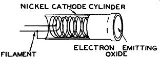
Fig. 3. Heater and Cathode Assembly
GRID CONTROL ELEMENT: The elementary cathode-ray tube illustrated in Figure 2 has no controlling element which can limit the number of electrons emitted from the cathode.
In television, some means must be provided for controlling the brilliancy of the picture.
This calls for an additional element, designated as the control grid, to be inserted between the cathode and the positively charged anode.
In modern tubes, this element is a metal cylinder completely enclosing the cathode element, as illustrated in Figure 4A. The strategic position of the control grid element constitutes a means of controlling the quantity of electrons admitted into the beam. This, in turn, limits the number of electrons impinging on the screen; hence the brilliancy of the pattern, because the more negative the control grid is biased with respect to the cathode, the fewer electrons in the beam, and the less the intensity of light produced on the screen. The direction of the electron emission is governed by an aperture in the disc at the end of the grid cylinder.
The lines of force of the electrostatic field developed by the difference of potential between the two elements, that is, cathode and control grid, and their effect on the beam, are illustrated in Figure 4B. If the voltage on the control grid is made more negative with respect to the cathode, fewer electrons will be admitted to the beam.
If the control grid is sufficiently negative, it will completely shut off or blank out the beam.
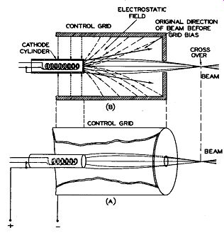
Fig. 4. Action of Cathode and Control Grid Assembly.
In earlier cathode-ray gun construction, the negative field of the control grid also lessened the effect of the positively charged focus anode located immediately beyond the control grid and further contributed to the reduction of the beam. Many present production cathode-ray tubes employ a different physical placement of the anodes to reduce this inter-action of control grid (brilliance) and focus adjustments. A complete discussion of anode function and structure is given later in this text.
Also, the action of the negative field associated with the control grid causes the beam to have a cross-over point after it passes through the control grid aperture; refer to illustration 4B. This cross-over action is similar to a lens and concentrates the beam of electrons to a fine point. Hence, the phrase "electron optics." A close resemblance is given in Figure 5.
Summing up the foregoing, the control grid has three functions:
1. Controls brilliancy at the cathode ray screen from zero to maximum.
2. Lens action to concentrate the beam by effecting a cross-over.
3. Provides a means for inserting the video output from a television receiver.
A potentiometer is included for varying the control grid bias and provides manual control to enable the viewer to adjust the brilliancy of the picture to a comfortable level. In oscillography this control is referred to as the intensity control.
FOCUS CONTROL ELEMENTS: So far, we have been able to control the brilliancy of the spot, but yet another control is necessary; that is, the spot must be brought into sharp focus. The focusing of an electron beam in a cathode-ray is similar to the focusing of light, as illustrated in Figure 6. As under stood from previous discussion, the control grid did focus the beam to a point slightly beyond its (control grid)aperture, but the beam begins to widen again after the cross-over point; therefore, additional focusing is needed.
In the earlier types of electrostatically controlled television picture tubes, this was accomplished by having two cylindrical anodes, as illustrated in Figure 5.
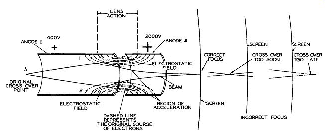
Fig. 5. Effect of an Electrostatic Field on an Electron Beam
The two anodes are operated at different potentials and the lines of force developed between the two elements establish the lens action in the following manner. The moving electrons will be subjected to forces as they enter the electrostatic field set up by Anode 1 and Anode 2. To understand clearly what takes place, let us refer to Figure 5. Here, the electron beam is seen entering the electrostatic field developed by a difference of potential existing between the two anodes.
Coming from point "A," the original cross over, the beam enters a new field. As the electrons cross the first static lines (1) and (2 ), Figure 5, the tendency is to change their course because the forces acting on them are repelling to negative charges due to the potential gradient existing between anodes 1 and 2. Although both anodes are positive with respect to the cathode, anode 1, operating at a much lower potential, is negative with respect to anode 2, creating an electro static field which tends to repel the electrons entering that field.
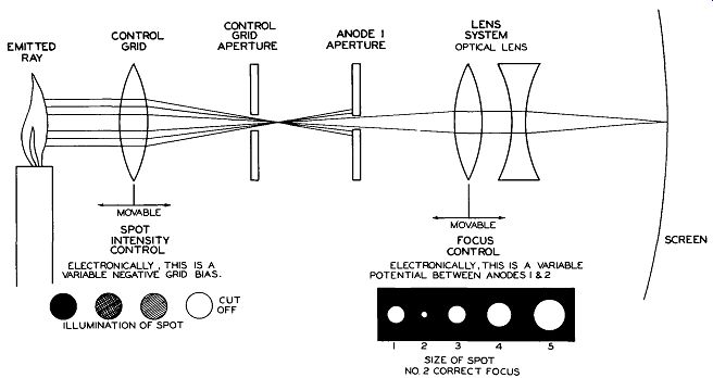
Fig. 6. Similarity of Light Ray and Cathode Ray
The electrons, traveling at a high speed, are gradually bent into a beam, the greatest repelling force occurring at a point somewhere between the two anodes. When the electrons of the beam converge near the axis of the tube (center), where the lines of force are running almost parallel to the axis, an acceleration takes place and the electrons in the beam gain velocity. At the end of anode 2, the field is relatively weak and the electrons keep their direct course, aided by the velocity gained while traveling through anode 2. In this construction, the two anode cylinders are similar to the grid cylinder, with the exception of anode 1, which is generally longer and has two aperture discs spaced to provide better focus action.
After the beam has passed through anode 2, a second cross-over point takes place.
This second cross-over point should be adjusted so that it takes place when the beam arrives at the surface of the screen.
The focus of an electrostatic type cathode-ray tube, construction of which is shown in Figure 5, is generally adjusted by varying the voltage applied to anode 1. This controls the amount of force the electrostatic field exerts on the electron beam, and by rotating the focus control and observing the screen, it is very easy to bring the beam into sharp focus.
Before proceeding into a discussion of variations in anode structure from the type just discussed and illustrated in Figure 5, it might be wise to clarify the terminology existing at present with regard to these elements.
Since the first cathode-ray tubes employed in television corresponded to the two cylindrical anode type illustrated in Figure 5, the terms "first anode," and "second anode” were quite logically used for reference purposes. However, with the advent of new constructions wherein more than two anodes, or physically split anodes, are used, we begin to have difficulty in titling them by their relative position in the tube, and it is, therefore, advisable to label them by their use or purpose. Consequently, anode lt. which controlled the focus action of Figure o, can be called the "focus anode," and anode 2, the higher potential element, can be referred to as an "accelerating anode."
FOCUS ANODE DEFLCTION PLATES
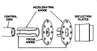
Fig. 7. Typical Anode Assembly Figure 7 shows a more recent form of cathode-ray
anode assembly in a typical 7 inch electrostatic tube. As noted in the illustration,
the cylindrical anode adjacent to the control grid is an accelerating anode
instead of a focus anode as employed in Figure 5. The circular disc with the
rather large aperture, following the accelerating anode, is actually the focus
anode. The shorter cylindrical anode combined with the second circular disc
is electrically connected to the first cylindrical anode and is considered
part of the accelerating anode structure. The reasons for this construction
are as follows:
1. Removal of the focusing anode from its position near the control grid lessens any inter-action between intensity and focus control adjustments.
2. By proper placement of the focusing anode, it is possible to make its aperture larger and thereby reduce the amount of beam current drawn by this anode, lessening its effect on the beam intensity.
3. Item 2 is made possible because of the separation of portions of the accelerating anode, enabling the insertion of the focusing anode.
4. In any cathode-ray tubes which em ploy appreciable focusing anode current, the focusing control circuits must use sufficient bleed current to insure reliable operation.
With the construction outlined in Figure 7, it is possible to considerably reduce or eliminate the requirement for bleed currents.
It should be borne in mind that construction of the tubes may vary according to the manufacturers' preferences of electrical design and physical support of the various elements.
Summing up, the focus and accelerating anodes have two functions:
1. Focusing the beam for sharp detail of the image on the screen. The focusing is manually controlled.
2. Acceleration of the beam.
GENERAL SUMMATION TO THIS POINT: The cathode-ray tube requires a high potential between the cathode and the accelerating anode. The voltage of the focus anode is usually around one-fifth that of the accelerating anode, and is normally variable to provide a means of focusing. The bias supply to the control grid also is made variable to provide a means of controlling the brilliance.
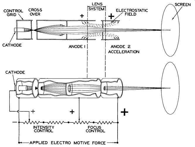
Fig. 8. Electron Gun Assembly
The assembly so far discussed constitutes the electron gun, so called because it shoots bullets (negative particles) to a screen or target, Figure 8 shows a typical electron gun assembly.
BEAM DEFLECTION ELECTROSTATIC: Now that we have produced and accelerated the beam and are able to manually control its intensity and focus, a means must be provided to give it universal motion of deflection; that is, a horizontal and vertical movement within the area of the fluorescent screen. To obtain this effect, two sets of deflecting plates, with horizontal and vertical orientation (see Figure 9 ), are mounted in the neck of the tube and so arranged that the electron beam passes between the plates of each pair, after it has sped through the anode structure toward the screen.
The complete assembly of a cathode ray tube with deflection electrostatically controlled is illustrated in Figure 10. Since the electrons in the beam are negatively charged, their movement will be governed by the basic law of attraction and repulsion; that is, "like charges repel one another, unlike charges attract one another." Therefore, a positively charged plate will attract, while a negatively charged plate will repel.
An electrostatic field exists between two adjacent plates of opposite polarity. Referring again to Figure 9, when an electron is shot into an electrostatic field whose lines of force cross its path, the electron has a tendency to drift off of its normal course toward the positively charged plate. The reason the electron actually crosses the lines of force is due to its own momentum, since the action of the static lines is to pull the electron in their direction. The high speed at which the electron beam passes through the static field delays slightly its deflection, thus preventing it from hitting the positive plate. Therefore, the amount the beam is deflected off of its normal course is dependent on the velocity of the beam and the strength of the deflecting field. The horizontal and vertical deflection could be increased by increasing the distance between the point of deflection and the screen; this, of course, would increase the physical length of the cathode-ray tube. It will be noted in some specifications that the sensitivity of the horizontal deflection plates is greater than that of the vertical, since the horizontal plates are further from the screen.
However, when a cathode-ray tube is designed, the velocity of the beam and the position of the electrodes is fixed; therefore, to increase the deflection, the deflecting voltage must be increased.
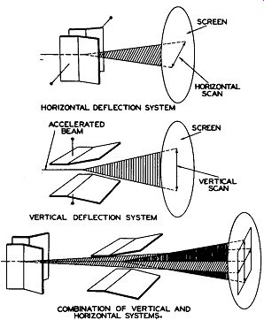
Fig. 9. Electrostatic Beam Deflection Systems
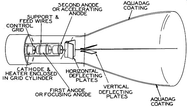
Fig. 10. Electrostatic Focus and Deflection
The distance the beam or spot is moved across the screen by an applied voltage of one volt across the deflection plates, is called the deflection sensitivity.
Another way of increasing the deflection sensitivity is to increase the length of the deflection plates so that the static field is active on the beam for a longer period of time. In this case it will be necessary to bend the ends of the plates to form a flare; see Figure 9.
EFFECT OF A FAST MOVING LIGHT SPOT ON THE FLUORESCENT SCREEN
The capability of the human eye to retain an image is about 1/16 of a second after it disappears. This is indicated by the practice followed in the projection of motion pictures where a series of still pictures is projected on the screen, in such rapid succession that the eye cannot detect them as separate pictures.
In a cathode-ray tube the beam is swept so fast that the moving spot appears as a straight line. If the beam is swept over the same line or path at least 16 times a second, the spot appears to the viewer as a continuous line of light, without flicker. Therefore, if the combined action of the horizontal and vertical deflection voltages sweeps the beam horizon tally and vertically at the same time, a frame of light will appear on the screen. See Figure 9. The summation is as follows: A small spot of light appears at the point where the electron beam strikes the screen.
If the beam is deflected left to right and top to bottom very rapidly, the whole screen is illuminated. In television, this pattern of light is called a raster.
In early cathode-ray tube practice, deflection voltage was obtained from single ended amplifiers. One plate of each set of deflection plates was tied together and, in turn, connected to the accelerating anode.
When a deflection voltage was applied to the deflection plates a difference of potential existed between the accelerating anode and deflection plates causing a defocusing action and change in velocity of the beam. This effect is called astigmatism.
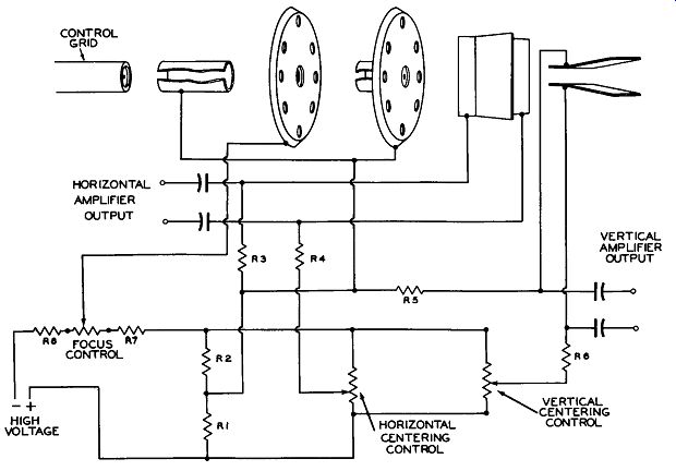
Fig. 11. Typical Centering Control Circuit
In present construction of cathode-ray tubes, separate terminals are provided for each deflection plate, making possible the use of push-pull deflection amplifiers. The aver age potential remains constant between the plates of either pair of plates, since the potential of one plate is increased by an amount equal to the decrease in potential of the other plate. This minimizes any defocus action or change in velocity of the beam.
Some tubes also have a ring or element placed between the horizontal and vertical deflection plates and connected to the accelerating anode. Its purpose is to prevent the defocusing action which would be the result of any disturbing field set up between the pairs of deflecting plates.
Summation at this point is as follows:
1. We have finally produced a frame of light, the intensity of which can be con trolled.
2. Knowing that the frame is built up of small spots of light, it is now possible to insert into the control grid circuit of the cathode-ray tube, a video signal that will modulate the beam, causing each spot to vary in brilliancy. An analogy of this action may be obtained by looking at a picture in a news paper under a magnifying glass, It can be seen plainly that each small dot varying from black to white, through various shades of grey, produces the necessary elements to form a picture, CENTERING CONTROLS: There is an additional control function required to insure proper operation of the cathode-ray tube as used in television applications.
For correct operation, the cathode-ray electron beam, in the absence of deflection potentials, should strike in the center of the fluorescent screen. Effects such as stray electric and/or magnetic fields, distortion of forces within the cathode-ray tube itself, and aging or replacement of the tube or its associated supply components may cause the beam to move off center. To correct any "off center" condition that may exist, two centering controls are generally made avail able on the back apron of the receiver chassis to enable the serviceman to adjust the picture frame for proper horizontal and vertical positioning.
Figure 11 illustrates a typical centering control system. A high positive potential is applied across the divider network consisting of R1, R2, R7, the focus control, and R8.
From the junction of R1 and R2, potentials are applied to the accelerating anode, through R3 to one horizontal plate, and through R5 to one vertical plate. As shown in the illustration, each of the centering controls parallels the combination of R1 and R2. The variable arm of the horizontal centering control supplies the remaining horizontal deflection plate through R4, and, similarly, the variable arm of the vertical centering control supplies the remaining vertical deflection plate through R6.
When the variable arms of the centering controls are at their mid-point, no DC potential exists between the individual plates of each pair of plates.
Consider for a moment the horizontal plates, A simplified diagram of their supply circuit is shown in Figure 12.
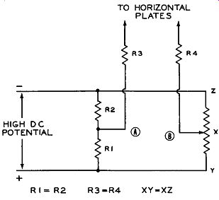
Fig. 12. Simplified Beam Centering Circuit.
Since R1 is equal to R2, and XY is equal to XZ when the centering control is at mid-point, we have, in effect, a bridge circuit and no potential will exist between the arms of this bridge represented by points A and B in Figure 12. It will be seen that one horizontal plate is supplied by each bridge arm through the series resistors R3 and R4, which are equal in value. Thus, it is possible to maintain a condition of no DC potential between these plates, Should an "off-center" electron beam be encountered, due to any one or a combination of the effects mentioned previously, the beam may be centered by moving the control arm to provide a counteracting DC potential.
By applying the above analysis to the vertical centering supply circuit, it will be seen that an identical method of control is used,
------------------
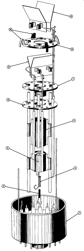
Typical 7-inch Cathode-Ray Tube Structure Using Electrostatic Deflection
1. Medium Shell Di-heptal Base. (Designation 14-G)
2. Heater Element
3. Cathode Sleeve
4. Control Grid
5. Accelerating Anode
6. Focus Anode
7. Accelerating Anode
8. Horizontal Deflection Plates
9. Barrier Anode
10. Support and Aquadag Contact Springs
11. Vertical Deflection Plates Sample Tube Structure
Courtesy Sylvania Electric Products, Inc.