The satisfactory performance of a television receiver is more dependent on the efficiency and placement of the antenna and lead-in, than on any other single factor encountered in the installation and maintenance of the set.
Receiving antennas for television are far more critical in performance, and play a more important role in the production of satisfactory television reception, than do the antennas employed for ordinary sound or FM reception.
Sets for AM or FM sound reception are sufficiently sensitive, and the broadcast signal strength is sufficiently great, to render the use of out side antennas unnecessary in most instances. The design trend, of the last few years, has been to incorporate the antenna within the receiver cabinet. A loop is normally employed for the broadcast band and a simple half "dipole" or "doublet" for the FM band.
Reception with such a simple installation is usually satisfactory except when the receiver is located in a steel building.
It is seldom possible to operate a television receiver without an outside antenna. An exception to this statement would be the case of a receiver operating in a position close to the transmitter, and where reception of only the single station is required.
Many unique factors exist in television wave propagation which are not encountered, to as great a degree, in other forms of broadcasting. A discussion of these factors will assist the television service technician in understanding the nature of the major problems which will be experienced, and in arriving at the best compromise solution under each particular condition.
The elements of the antenna problem which must be considered are:
1. The nature of radiation and propagation of radio waves in the television bands.
2. Horizontal versus vertical polarization of television waves.
3. The wideband nature of the television channel, and its relation to the susceptibility of the system to noise.
4. "Ghost" images due to multiple signal paths caused by the reflection of the signal from buildings, mountains, hills or other obstructions.
5. "Ghost" images due to "mismatch" between the impedance of the transmission line (lead-in) and the antenna or receiver input circuit. (Reflections in the line.)
6. The necessity for special types of antennas to achieve a desired directional reception pattern.
7. "Wideband" antennas to allow reception of stations widely separated in the television frequency spectrum.
8. Problems peculiar to "fringe" reception. (Reception of stations beyond the limits of the "primary service" area.)
PHENOMENA OF RADIATION AND PROPA GATION OF WAVES IN THE TELEVISION SPECTRUM: In our study of the nature of the television channel, with its vestigial amplitude modulated video, and frequency modulated audio components, we have seen that a channel width of 6 megacycles is required for high definition television. The modulation process requires that the carrier frequency be made at least ten times the top modulating frequency. For this reason, the carrier frequencies of the television transmitters have been assigned in the portion of the radio spectrum above fifty megacycles.
The standard classification of the part of the spectrum between 30 and 300 megacycles is V.H.F. (Very high frequencies). The propagation characteristics of V. H. F. waves are considerably different from those of the lower frequencies employed for sound broadcasting.
A review of the manner in which radio waves travel from the transmitter to the receiver, as the frequency of the carrier is increased, will be helpful in understanding some of the transmission phenomena which occur in the television bands.
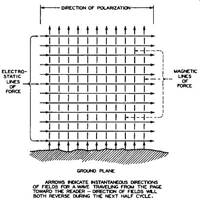
Fig. 145. Graphical Representation of an Horizontally Polarized Electromagnetic
Wave Front
After a radio wave has traveled several wavelengths from the transmitting antenna, it will be found to consist of two components: an electrostatic field and a magnetic field. These two fields consist of "lines of force" at right angles to each other. The energy in the radio wave is divided equally between these two traveling, alternating fields. Figure 145 shows a graphical representation of part of the wave fr on t of an electromagnetic wave in space.
Since the wave is traveling in all directions from a point source (the transmitting antenna), the lines of Figure 145 represent a small portion of a spherical surface.
POLARIZATION OF THE TRANSMITTED WAVE. The direction of the lines of force of the electrostatic component of the wave define the direction of polarization. In the graph of Figure 145, these are the solid horizontal lines and such a wave is said to be "horizon tally" polarized with respect to the earth's surface. If the direction of the electrostatic lines are perpendicular to the earth's surface, the wave is said to be "vertically polarized". In the V.H.F. portion of the spectrum, utilized for television, the plane of polarization of the transmitted wave is the same as the position of the transmitting antenna with respect to the earth's surface; that is, a vertical antenna produces vertically polarized waves and a horizontal antenna produces horizontally polarized waves. The television broadcasters of the United States have adopted horizontal polarization and this type is becoming standard for television transmission.
The reasons advanced for the choice of horizontal polarization are:
1. Many types of "man made" interference as well as interference from other radio communication transmitters is vertically polarized and the horizontal polarization of the receiver antenna helps to reduce interference from these sources.
2. Horizontally polarized wave s suffer less loss or "attenuation" when reflected from the earth or in passing through the atmosphere.
TYPES OF WAVE PATHS BETWEEN THE TRANSMITTER AND RECEIVER. Radio waves of different carrier frequencies follow different paths between the transmitter and the receiver. The waves, themselves, are basic ally the same and would act alike in free space (beyond the atmosphere of the earth). The effect of the earth's surface, the nature of the earth's atmosphere and the presence of objects, comparable in size to the length of the wave, modify the transmission path as the frequency of the wave is changed.
The paths which radio waves follow can be classified generally in two main groups: ground waves and sky waves.
The ground wave group, which is of main interest to us in our consideration of television transmission, can be further subdivided into: a "direct" wave, a "surface" wave, and a "space" wave.
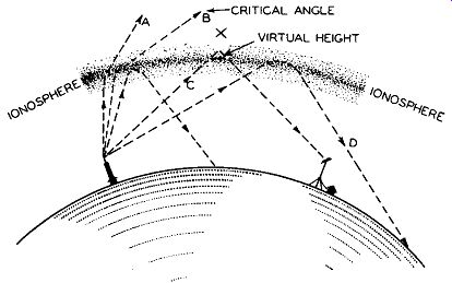
Fig. 146. The Bending of Radio Waves Back to the Earth from the Ionosphere.
(Occurs at Frequencies below 40 mhz)
The sky wave, which accounts for long distance reception on the lower frequencies such as the broadcast and short wave bands, is "bent" back to the earth by ionized "layers" or "strata" in the earth's upper atmosphere.
Figure 146 shows this type of transmission.
The ionized "layer", which consists of atoms and molecules of the air (principally nitrogen and oxygen), acts like a mirror at the "virtual" height "X". In reality the wave front is steadily bent as it passes into regions of gradually increasing free electron density and emerges toward the earth as though it had been reflected. The amount of bending which a wave will encounter is a function of the wavelength. For each wavelength there exists a critical angle (see B of Figure 146) at which the wave will pass through the "layer" and not return to the earth. Frequencies of more than 30 to 40 megacycles are not returned by the ionosphere, except under unusual sporadic conditions and therefore this type of wave-path cannot be depended upon for television transmission.
GROUND WAVE OR LINE-OF-SIGHT TRANSMISSION ON TELEVISION FREQUENCIES. The action of frequencies in the range above approximately 40 megacycles is often termed "quasi-optical" since the waves act in a manner similar to light rays. (Quasi means "as if" and optical means "light" in Latin.) Radio transmitters operating in this frequency range, such as television stations, employ as high an antenna structure as practicability and economics will permit. The radio carrier waves leaving the antenna act in a manner similar to the rays of light which might be produced if a powerful electric light were to be mounted on the top of the antenna mast.
The curvature of the earth would cut off these light waves at the horizon. The horizon distance can be extended by erecting a tower for the observer of the light.
Waves emitted by transmitters in the television bands exhibit this "line-of-sight" action as shown in Figure 147A, In the case of the radio waves, however, the cut-off at the horizon is not sharply defined. In traveling through the air, the wave is bent or '' refracted" slightly toward the earth and the V. H. F. radio horizon is considered to extend some 15% beyond the "line-of-sight" or optical horizon. Beyond this radio horizon the strength of the signal decreases very rapidly.
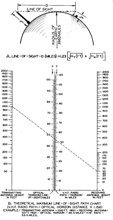
Fig. 147. V.H.F. Path Length as a Function of Height of Transmitting and
Receiving Antennas
Figure 147B shows, by means of a "nomograph" chart, the effect of the height of the transmitting and receiving antennas, on the optical horizon (shown at X) and the radio path horizon (shown at Y). This chart is calculated for a smooth, spherical earth. If the transmitting and receiving antennas are at different relative heights above sea level, this difference should be taken into account in calculating the radio path horizon. The pres enc e of large intervening objects such as buildings or hills can reduce seriously the signal level and thus the range of satisfactory reception. Figure 147B indicates the advisability of locating the receiving antenna as high as possible.
WAVELENGTHS OF THE TELEVISION CHANNELS. In the range of frequencies assigned to television transmission (54 to 88 megacycles and 174 to 216 megacycles) the length of the electromagnetic wave in space is small when compared with the size of obstructions such as buildings. This accounts for some of the peculiar transmission phenomena encountered, which will be described when we examine the effect of reflections. Another consequence of the short wavelength, on the '' credit side of the ledger'', is the fact that highly efficient antenna, which are "resonant" to the wavelength and possess directional characteristics, can readily be constructed.
For these reasons it will be instructive, at this time, to review some of the fundamental relationships between the frequency of an electromagnetic wave and its wavelength. It will also be valuable for the television service technician to become familiar with the actual wavelengths in feet of the television carrier frequencies of stations in his locality, since the size of the antenna structure required is directly related to the wavelength.
All electromagnetic waves (cosmic waves, x-rays, ultra-violet waves, light, infrared and radio waves) travel through space with the same velocity or speed. This velocity has been quite precisely measured as 299,796,000 meters per second. For our purposes, this figure can be "rounded off" to 300,000,000 meters, or 186,000 miles per second.
The distance in space which an electromagnetic wave travels in one cycle (360° of its sine wave oscillation) is called one wavelength. Figure 148 shows the relationship of wavelength, velocity and frequency. It will be seen that, when the velocity is expressed in feet per second and the carrier frequency in cycles, both numerator and denominator of the fraction can be divided by one million and the simple expression, 984 divided by the frequency in megahertz , results. The wavelengths encountered in the television bands lie between four and twenty feet.
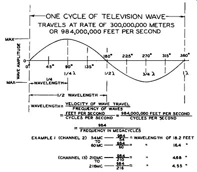
Fig. 148. Relation of Carrier Frequency to Wavelength of Television Channels
A handy '' rule--of--thumb '' which is apparent from Figure 148 is that the television wave travels approximately 1000 feet in one microsecond (actually 984 feet). This in formation is of value in determining the effect of reflections of the wave from objects.
TELEVISION CHANNEL BANDWIDTH IN RELATION TO THE ANTENNA PROBLEM. We have seen that television requires an extremely wide band to accommodate the video modulation and sound. One of the "axioms" or principles of electrical communication, when employing amplitude modulation, is that the noise susceptibility of a system is proportional to its band-width.
This situation is aggravated by the fact that automobile ignition systems produce interference which, due to the length of the spark plug wiring, is tuned in the television bands.
Fortunately the radiated interfering field drops rapidly with distance from the car. If the antenna system is relatively high, not sensitive to vertically polarized waves and has a balanced lead-in system, the effects of this, and other types of man made interference, can be reduced. This consideration is an added re as on for the installation of an efficient antenna.
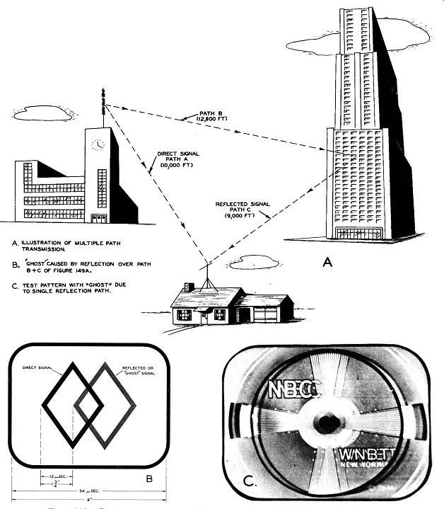
Fig. 149. Production of a Ghost Image by Multiple Path Transmission
"GHOSTS" DUE TO MULTIPLE PATH TRANSMISSION. Before considering the television antenna itself in detail, it will be instructive to examine some of the distortions of the picture which are caused by vagaries of the transmission path and to determine their causes. The expedients employed in antenna design to overcome or alleviate these defects will then be discussed.
Figure 149A shows a set of conditions which might occur in the residential section of a city. The direct signal arrives at the receiver over path A (assumed to be 10,000 feet from the transmitter). At a distance of 12,800 feet from the transmitter, an office building acts as a "mirror" and reflects the signal to the receiver over path C (9,000 feet). The combined path B plus C is 21,800 feet. This reflected wave path is 11,800 feet longer than the direct path. We find from the wavelength frequency relations of Figure 148 that the wave travels at the rate of 984 feet per microsecond.
In this instance the reflected wave will arrive 11,800/984 or 12 microseconds later than the direct wave.
Figure 149 shows the effect of the delayed or "ghost" signal on the picture. The horizontal scanning time relations discussed will serve to explain the image displacement . Approximately 54 microseconds elapse during active scan of one line. On a ten inch tube, the horizontal dimension of the picture is about eight inches. The signal arriving over paths B plus C requires twelve microseconds more than the direct path, and during this time scanning will have advanced one and three quarters inches. Thus, a second image, due to the reflected wave, will appear displaced from the main image as shown. In general this "ghost" image will suffer some loss of signal strength due to imperfect reflection and absorption of energy and will therefore be less intense than the image caused by the direct signal.
Figure 149C shows the appearance of a "ghost" of the type just discussed, as photo graphed from a television receiver with the station test pattern as a subject. In the example just discussed and in Figures 149B and 149C the ghost is caused by a single reflection.
In many cases a series of overlapping ghost images will appear due to multiple reflections from a number of buildings or other obstructions. When such multiple ghost images arrive over paths only slightly longer than the direct signal path, the effect on the picture is to "widen" lines and obscure the fine detail.
Since this" smears" the picture, it has become known in television slang as a “smear" ghost.
The types of ghost images just discussed are all positive in nature. By this is meant the fact that a black line in the picture will be represented by a black line in the ghost and conversely, white picture elements will be followed by a white ghost. A negative ghost (see Figure 150) can be caused by reflected signals which arrive at the TV antenna in such phase as to cause partial or complete cancellation of portions of the video modulation envelope. These can be caused by re-radiation of the carrier from metal objects which are of a size comparable to the wavelength of the video carrier frequency affected. A similar effect c an be caused by defects in the video amplifier. (See Figure 230.)
Fig. 150. Negative Ghost Caused by Partial Cancellation of the Carrier.
Elimination of ghost images, or their reduction to such a point that they are no longer objectionable, is accomplished by making use of the directional properties of certain types of antennas. The theory and application of such antennas will be covered later in this section.
In certain urban locations the receiving location is shielded by buildings from a direct line -of -sight signal from the transmitter. In this case, one of the reflection paths will often produce a stronger signal than the "shadow" of the direct path. The antenna, in this case, is "beamed" to a cc e pt or favor the strongest reflected signal. The dominant reflection is then considered to be a "substitute" primary signal, and the direct path produces a ghost which must be suppressed.
GHOSTS DUE TO REFLECTIONS IN THE LEAD-IN OR TRANSMISSION LINE. The resonant type of antennas employed for television require a special type of lead-in. This lead-in or transmission line consists of either a "parallel wire" line, a "twisted pair" line, a shielded "twisted pair" line or a "coaxial" (concentric) cable.
The reasons for these special types of lead-ins are twofold: to transfer the maximum amount of energy from the low impedance type antenna to the first tube input in the receiver, and to restrict signal pick-up to the antenna only.
Maximum energy transfer of the intercepted signal from the antenna to the input amplifier of the television receiver requires that the "characteristic impedance" of the line be matched to the impedance of the antenna and the impedance of the receiver input circuit.
The various types of lead-in constructions and their application will be covered in greater detail later. At present we will consider the effect of line mismatch in the production of ghost images.
When the impedance of the transmission line is considerably different from that of the antenna or the receiver input, energy will be reflected from the receiver, back to the antenna, and back to the receiver again. This will produce a ghost image when the reflection reaches the receiver. Unless the mismatch is of considerable degree, only one secondary or ghost image will be produced.
In the case of ghost images caused by line, mismatch only a small displacement of the image occurs due to the relatively short length of the transmission line. If the length of the lead-in is less than 70 feet, the ghost will be so close to the main image that the eye cannot distinguish it as a separate image. The horizontal resolution is impaired in this case and the image appears to be improperly focus ed.
It is possible to distinguish between a ghost image due to line reflection and one due to reflection by some object. If an assistant rotates the antenna while the service technician watches the image, it will be found that a ghost due to line mismatch will not change.
If, on the other hand, the ghost is due to a reflected path it will change in intensity with respect to the main image, due to the directional characteristic of the antenna.
THE HALF WAVE DIPOLE AS A TELEVISION RECEIVING ANTENNA: Having reviewed the nature of wave propagation and some of the basic phenomena of transmission of television signals, we are prepared to examine the types of antennas which have been developed to cope with the problems encountered.
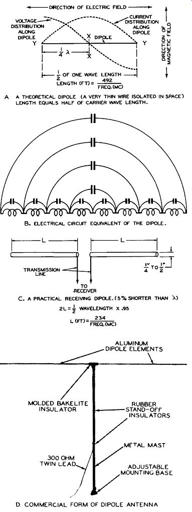
Fig. 151. The Half-Wave Dipole Antenna. (Photo Courtesy Ward Products Corporation)
A. A THEORETICAL DIPOLE (A VERY THIN WIRE ISOLATED IN SPACE) LENGTH EQUALS Half Of CARRIER WAVE LENGTH.
B. ELECTRICAL CIRCUIT EQUIVALENT Of THE DIPOLE.
C. A PRACTICAL RECEIVING DIPOLE. ( 5 % SHORTER THAN A) 2L=½ WAVELENGTH X .95
D. COMMERCIAL FORM Of DIPOLE ANTENNA
Since the advent of commercial television in the United States, there has been no single phase of television development which has seen more concentrated activity than the search for types of antennas to meet the requirements.
Among the desirable characteristics are: more uniform response or higher pickup and sharper directional pattern. As this course is being written, new antenna designs are appearing daily and the present study will cover basic types and some of the variations which have found widespread use up to this time. The television service technician will undoubtedly find many technical articles on further antenna developments appearing in the radio press from now on.
Practically all types of antennas used for television reception are variations of the basic half-wave dip ole or "Hertzian doublet". An understanding of the action of this "resonant" type will help in the study of more complicated "arrays". The basic nature of the half-wave doublet is indicated by the fact that it is used by the industry as a standard against which the efficiency of other types is compared.
Figure 151A shows the concept of a half wave dipole in space. If such an antenna is made of very small wire , and could be far removed from the influence of the earth, its resonant electrical length would be equal to its physical length. This length in turn would be one half of the wavelength of the electromagnetic wave in space.
Although Figure 145 shows the electric and magnetic fields as fixed uniform lines, it is to be understood that both of these fields are varying in intensity at a sine wave rate.
Thus, a varying magnetic field will induce an alternating flow of electrons in the dipole wire and a wave of current will pass down the dipole to its end. At the end, reflection will occur and a "standing" wave will build up along the wire having the voltage and current distributions shown in Figure 151A. Since the length of the theoretical dipole of Figure 15 1A is exactly equal to one wave in space, the build up of voltage along the wire and the current through it will reach a resonant condition similar to that found in a parallel tuned circuit.
Actually, the dipole may be considered as such a tuned circuit, but in this case the inductance is "distributed" along the length of the wire and the capacitance consists of many elements across the individual small inductances. This tuned circuit equivalent is shown in Figure 151B. The foregoing discussion has been concerned with an hypothetical or theoretical dipole which could never exist in actuality since it requires that the dipole wire be infinitely small in diameter compared with its length, and that the dipole is positioned at a distance so far from surrounding objects, including the earth itself, that no influence of such objects exists. In practice, the dipole must be erected within a few wavelengths of ground and must be physically large enough in diameter to be self-supporting. Both of these requirements cause the velocity of wave travel in the practical dipole to be less than the speed of electromagnetic waves in free space.
While the actual length of the dipole, for resonance, will vary slightly depending upon the proximity of other objects, it has been found that a good average figure for the reduction in length, due to the proximity effect, is 5%. Or, in other words, the half wave length value obtained from the formulas of Figure 148 should be multiplied by .95 to find the length of the required dipole for any given frequency. A practical dipole formula is found in Figure 151C, and a commercial dipole antenna for installation on a roof is illustrated by the Figure 151D. The dipole produces the greatest current when it is parallel to the electric field of the wave front. In other words, a line drawn from the receiving location to the transmitter should be at right angles or perpendicular to the length dimension of the dipole. As the dipole is rotated with respect to the distant transmitter, its response varies in the manner shown in Figure 152A. A curve of this type is known as a "polar" response diagram. The relative response at different angles away from the "normal" or maximum response position, is determined by taking the ratio of the length of the radius at any point to the maximum radius, or line A-A. The response curve of Figure 152A represents a cross section taken in the plane of the antenna. The response to waves arriving from the sky or reflected from the ground at any angle is determined by the solid figure obtained by rotating curve 152A around the axis X-Y as shown in Figure 152B. This solid figure is seen. to be "doughnut shaped".
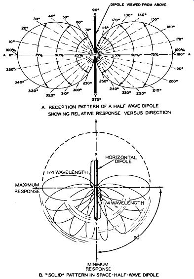
Fig. 152. The Reception Pattern in Space of a Half-Wave Dipole
A. RECEPTION PATTERN or A Half WAVE DIPOLE SHOWING RELATIVE RESPONSE VERSUS DIRECTION; B. "SOLID' PATTERN IN SPACE·HALF·WAVE DIPOLE
It is also seen from the reception pattern (Figure 152A) that the simple dipole is "bi directional", and will receive equally well from the front or rear, but shows practically no response at right angles or in line with the length of the dipole. This directional characteristic is of value when it is desired to discriminate against spurious reflection objects which would produce ghosts in the television picture. The simple dipole is a satisfactory television receiving antenna in locations in which the signal strength is high, only one station (or stations close to each other in frequency assignment) is to be received, and in which the multiple reflection or ghost problem is not severe.
If greater directional selectivity or more signal pick-up is required, the pattern of the simple dipole, and its response, can both be improved by the use of additional elements known as "reflectors and directors". The use of these elements, in more complicated antenna structures or "arrays", will be covered in detail later.
The impedance of the simple half-wave dipole at its center is approximately 72 ohms and, for maximum energy transfer, the lead-in or transmission line should have a characteristic impedance of this value. Such value of impedance is rather low and is best suited to the coaxial type transmission line. It is found that the mismatch of the antenna to the transmission line can vary as much as two to one without serious loss in the signal and without the production of disturbing ghosts, providing the line is appropriately matched to the receiver input. This means that transmission lines having impedances between 36 ohms and 144 ohms can be used with the half-wave dipole.
The simple half-wave dipole is most efficient when its length is correct for a particular carrier frequency. If several stations in adjacent television channels are to be received with a simple antenna, its length should be made correct for the geometric mean of the lowest and highest channel frequencies required. For example, if a station on channel three (video carrier frequency 61.25mhz), and a station on channel six (video carrier frequency 83. 25mhz) are to be received with approximately equal antenna response, the dipole should be made the correct length for the geometric mean of these frequencies, i. e.: ?61.25 mhz x 83.25 mhz = 71.4 mhz.
Each dipole section would thus be 234 divided by 71.4, or 3.28 feet long (3 feet--3-3/8 inches).
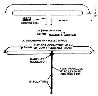
Fig. 153. The Folded Dipole. Photo Courtesy Ward Products Corporation
THE FOLDED DIPOLE. If two half-wave dipoles are placed closely parallel to each other with their ends connected, the received currents will be "in phase". The effect of the reaction of one dipole upon the other is to increase the impedance at the center of either dip ole from 72 ohms to approximately 300 ohms. Figure 153A shows such a folded dipole with the formula for calculating the required dimensions. The folded dipole possesses several advantage s over the simple single half-wave dipole:
1. Its higher impedance provides an ideal match for the popular polyethylene insulated parallel, or twin-lead, flat strip, trans mission line. The most popular type of this lead-in has a characteristic impedance of 300 ohms, and the majority of television receivers are designed to match a 300 ohm transmission line.
2. The folded dipole is receptive to a wider frequency band than the simple half-wave dipole, but possesses the same directional pattern.
3. Because of its design, it has a more rigid structure and will withstand greater wind pressure. Figure 153B shows a commercial form of such a folded dipole.
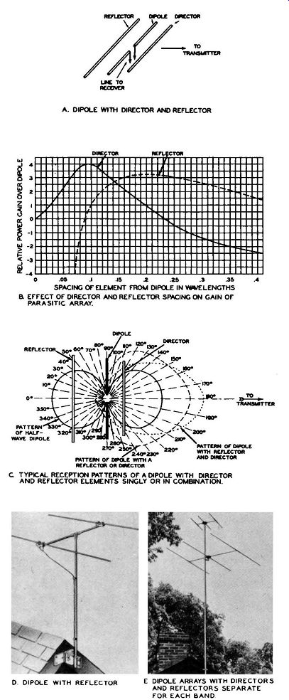
Fig. 154. The Dipole Antenna with" Parasitic" Elements (Directors
and Reflectors).
ANTENNA STRUCTURES EMPLOYING THE DIPOLE WITH REFLECTORS AND/OR DEFLECTORS--"YAGI ARRAYS": If a second half-wave dipole is placed parallel to and closer than a half-wave length from the receiving dipole, the magnetic and electrostatic fields of this element will modify the directional pattern of the receiving dipole and also increase its effectiveness or gain, compared with the performance of the dipole alone. When such a "parasitic" element is placed behind the receiving dipole, i.e., on the side away from the transmitter, it is known as a '' reflector" element. If, on the other hand, it is placed on the s id e of the dipole toward the transmitter, it is known as a "director". When employed as a reflector the element is made approximately 5% longer than the receiving antenna, and when employed as a director it is made about 4% shorter than the dipole.
This is equivalent to saying that the reflector is tuned to a frequency somewhat lower than the operating frequency and that the director is tuned to a slightly higher frequency. Figure 154A shows the arrangement of the dipole with a director and a reflector. The effect of the spacing of these elements on the power gain of the dipole antenna is shown in Figure 154B. Fi gure 154C compares the directional pattern and gain of the dipole alone, with a dipole using either a reflector or a director and also with a dipole using both a reflector and a director. It will be seen that the gain in the desired direction (toward the transmitter) is increased by these additional elements, and the directional pattern is made sharper so that stations at other points of the compass are not received with the same strength. For this reason, arrays of this type are beneficial in increasing the pick-up from the desired station and, at the same time, suppressing reflection paths which would produce ghosts.
These multiple element arrays are sometimes called "Yagi", since a Japanese by that name first proposed their use as directional antennas.
Arrays with directors and reflectors, while constituting an improvement over the dipole from the standpoint of pattern and gain, will not accept as wide a frequency band as the simple dipole or folded dipole. It is often necessary to erect a number of these antennas tuned to various stations in the band. Figure 1540 illustrates a dipole with reflector, while Figure 154E shows two sets of arrays on a single pole. The lower array is used for the low band of television frequencies, i. e., channels two through six; and the upper array of smaller size is used for channels seven through thirteen.
If increased gain and directivity are required, additional director elements can be added and arrays with as many as five elements are often employed for the reception of a single station, when the receiving location is at the edge or fringe of the service area.
Several such arrays will be illustrated when we discuss fringe reception. When five elements are used (a reflector and three directors added to the dipole) the antenna will accept only a single channel, and may not adequately cover the entire six megacycle band required for the channel.
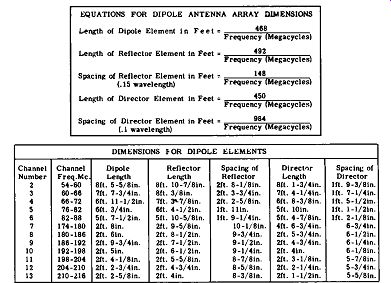
Fig. 155. Equations for the Dimensions of Practical Dipole Arrays
Figure 155 show s in tabular form the formulas for the length of dipole elements and the optimum spacing of these elements for each channel.
The following table shows the effect on the power gain of the array, as compared with the half-wave dipole used alone, and the ratio of forward reception to that of the reverse side of the antenna. These figures depend upon the care with which the system is adjusted. This is especially true with respect to the front-to back ratio, in which the highest values are obtained only at the frequency to which the system is tuned.
THE BROADBAND-PROBLEM. The half-wave dipole and arrays employing half wave elements are most efficient at the frequency for which they have been cut. Satisfactory performance is obtained with such antennas when only one stat ion serves the area, or when relatively high signal strength exists for several stations in the same television band. When reception of stations in both the low band (54mhz to 88mhz) and the high band (174 mhz to 216 mhz) is required, antenna structures of wider frequency response are necessary.
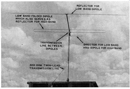
Fig. 156. Antenna Array of Folded Dipoles for Reception on Both Bands. Photo
Courtesy American Phenolic Corporation
The folded dipole exhibits the broadest frequency response of any of the types of television antennas discussed to this point.
Figure 156 shows a combination of folded dipoles which provide reception in both bands as well as directional discrimination.
In the low frequency band, this antenna acts as a three-element array in which the larger folded dipole is the receiving antenna, backed by a reflector, and the smaller folded dipole is properly positioned to act as a director. In the high frequency band, the small folded dipole functions as the antenna and the large dipole behind it acts as a reflector. The two dipoles are connected to each other at their center (high current) points, by the pro per length of twin-lead transmission line, so that a transition of operation occurs between the two bands. An additional feature of this array, as determined by the size of the elements and their spacing, is a low efficiency in the gap between the two television bands. This gap contains the FM broadcast stations (88mhz to 108mhz), which constitute a possible source of television interference.
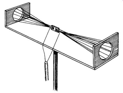
Fig. 157. The "Cage" Antenna, Variation of the Dipole for Wide Band
Reception
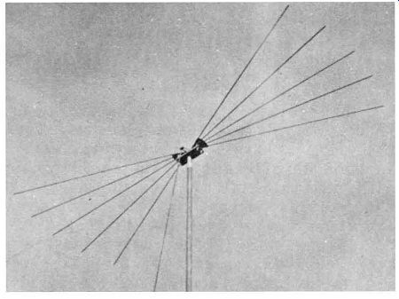
Fig. 158. Broadband Response by a "Fan" of Dipoles. Photo Courtesy
Andrew Corporation.
In the following text, means for increasing the bandwidth, other than by use of the folded dipole, are described and illustrated.
A Large Diameter Dipole. A dipole whose diameter is increased with respect to its length has a wider frequency response than the thin rod type. If the dipole is made in the form of a large cylinder, i.e., three to six inches in diameter, its "Q" will be decreased and its response to a band of frequencies broadened. Such a cylinder would be awkward to install and would possess a large surface which would be easily damaged by wind. An equivalent of the cylinder can be obtained by constructing a cage of wires with their ends connected to rings.
A Dipole in the Form of a Cone. The cage construction can further be modified to the form of two cones whose apexes meet at the lead-in or feed point. Figure 157 shows such an antenna.
A Modified "Cage” of a "Cone". Several dipoles arranged in the form of a fan, and with varying element lengths, will provide a pattern similar to the simple half-wave dipole, but will have broad frequency response characteristics. Figure 158 shows a commercial form of such an antenna, known as the "Di-Fan".
A Non-Parallel Dipole. The "V" type antenna, in its simplest form, consists of a dipole whose elements are not in a straight line, but are positioned at an angle of less than 180 degrees (in other words, "V" shaped). The effect of moving the dipole elements from a straight line is to broaden the band and still retain the directional pattern. Figure 159A shows the "V" antenna in its simplest form.
Figure 159B shows a modification of the "V" antenna known as the "Double-V" which, due to the parallel operation of the dipoles, shows an increased impedance and matches 300 ohm transmission line.
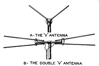
Fig. 159. The "V" and "Double-V" Variations of the Dipole
Antenna. Courtesy Technical Appliance Corp.
Special Dual Element Combinations.
Dipole combinations, in which the high frequency element is a physical extension of the low frequency element, can be made to exhibit wide frequency response. Many variations of this type of construction are appearing on the market, a number of which are illustrated in Figures 160A, B and C. Such antenna structures can also be used with reflector elements, as shown in Figure 160C. Their characteristics include wide band response, desirable directional patterns, and attenuation of the FM region. Certain of these antennas use balancing transformers, consisting of short lengths of coaxial cable, which aid in matching the transmission line.
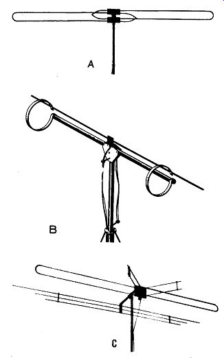
Fig. 160. Dual-Element, Wide Band, Television Antennas. Courtesy Dielectric
Products Co. Courtesy Tricraft Products Co. Courtesy L. S. Brach Manufacturing
Corp.
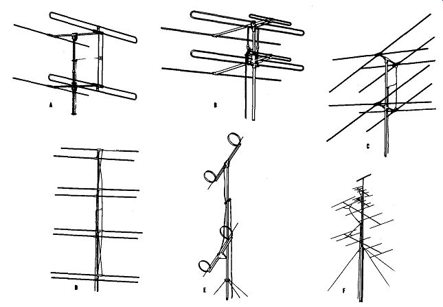
Fig. 161. "Stacked" Arrays for Higher Gain and Improved Directional
Pattern. (A) Courtesy Ward Products Corp,_(B) Courtesy American Phenolic Corp.
Courtesy Telrex Co. Courtesy Cole-Worner Corp. Courtesy Tricraft Products
Co. Courtesy Esse Radio Co.
"STACKED" ARRAYS. Any type of antenna can be used in a "stacked" arrangement in which a second identical antenna is erected directly above the first and in the same vertical plane. The antennas are positioned at a critical spacing (us u ally one half wave length), which provides in-phase operation to a common transmission line. The advantages of vertical stacking are twofold.
1. Additional gain is obtained due to the contribution of the added antenna.
2. Some vertical directivity is contributed by the mutual interaction of the antennas which discriminates against a reflected wave from the ground and confines the reception to the direct or sky wave. Figure 161 illustrates several versions of vertically stacked arrays.
ROTATABLE ANTENNAS. From the discussion of multiple path reception difficulties, it is evident that a highly desirable feature for a television antenna would be the ability to rot ate it to different positions as conditions might require. Figure 162 shows a remotely controlled , motor driven antenna which accomplishes this result. It consists of two half-wave dipoles posit io ne d at right angles to one another. The longer dipole is cut for the average frequency of the low frequency band, while the shorter dipole is tuned to the average frequency of the high band. A motor, housed within the antenna structure, allows rotation of the structure for optimum reception. Motion is accomplished by a control box located at the receiver. Slip-ring construction allows the antenna to be continuously rotated. On alternate 180 degree positions, the mechanism at the base of the antenna automatically switches from one band of TV frequencies to the other.
Other types of rotators are available which provide remote indication of the antenna position. With these devices the user may "log" the best position of the antenna for any given station, and subsequently return the antenna to the proper position.
HIGH BAND DIPOLE HOLLOW MAST FOR LEAD-IN AND MOTOR WIRING
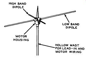
Fig. 162. Motor Driven Remote Control Antenna. Courtesy Kings Electronics.
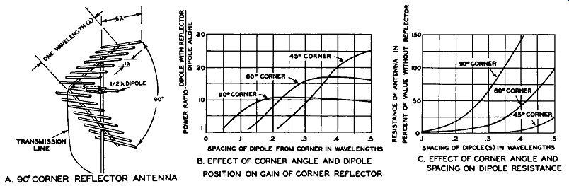
Fig. 163. The Corner Reflector Antenna
THE CORNER REFLECTOR ANTENNA.
Figure 163 shows an antenna structure which is of interest because it has a very high "front-to-back" ratio and greatly increases the pick-up of the dipole.
Its size, weight, and cost are justified in locations of low signal strength, high noise level and excessive interference.
This type of antenna was originally introduced for use in the frequency range known as U. H. F. (Ultra high frequencies), extending from 300 mhz to 3000 mhz . In this range, the corner reflector is usually made as a solid sheet of metal, since the dimensions of the dipole and the reflector are conveniently small.
When applied to the V.H.F. television region, a solid metal reflector would be exceedingly massive and easily damaged by high winds. It has been found that the solid sheet c an be replaced by a "grid" of rods made longer than the dipole element, and spaced closer than .1 wavelength, as shown in Figure 163A. Figure 163B shows the gain or ratio of power received with the reflector, to power received with the dipole alone--for various spacings of the dipole from the corner, and for corner angles of 90 degrees, 60 degrees, and 45 degrees. Figure 163C illustrates the influence of the corner reflector on the impedance of the antenna. This has been expressed in percentage change of dipole impedance since the corner reflector can be used with any type of dipole.
TYPES OF TRANSMISSION LINES: In our discussion of ghosts produced by reflections in lead-in or transmission line, we have indicated that maximum power transfer and freedom from reflections occur when the transmission line has a characteristic impedance which exactly matches both the antenna resistance and the input resistance of the radio receiver.
It is important that the power developed in the antenna structure be transferred to the grid of the first radio frequency amplifier tube with as little loss as possible in order to over-ride noise and produce high-contrast, steady pictures. To accomplish this, four types of lead ins or transmission lines have been used extensively. These are:
The Twisted Pair Line.
The Two-Wire Parallel Line.
The Coaxial or Concentric Cable.
The Shielded Two-Wire Parallel Line.
Each of these types exhibits its own particular characteristics of impedance range possibilities and loss or attenuation per foot.
THE TWISTED PAIR LINE. This type of transmission line is similar to twisted lamp cord but is made of higher grade insulation and weather proof covering. It is the most economical type of lead-in, but possesses several disadvantages. Its impedance is normally in the range of 100 to 300 ohms, depending upon the size of wire used and the thickness of the insulation. The losses are fairly high and the line is subject to deterioration by weather and dirt. Its use has been supplanted, in most instances, by more efficient types of lines.
THE TWO-WIRE PARALLEL LINE. The most popular type of television lead-in consists of two-stranded wires molded parallel to each other, at a uniform spacing, in a flat strip of insulating material. This low-loss material, ...
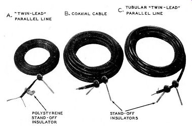
Fig. 164. Typical Television Transmission Lines. Courtesy American Phenolic
Corp.
... a plastic known as polyethylene , has excellent radio frequency properties including high resistivity, low water absorption and low dielectric constant. It is commercially avail able in impedances of 75, 150 and 300 ohms, which provide a match for any of the types of antennas discussed. Parallel wire lead-in is available in both clear and brown colored plastic. Each type is equally efficient.
The color has been added, in the case of the brown cable, to mask a slight color change which appears with aging of the transparent cable. Figure 164A shows this type of parallel lead-in cable together with two different types of stand-off insulators. Both types of insulators are used to support the cable away from buildings, and to keep it from twisting. The only disadvantage in the use of parallel lead cable is the fact that it is not shielded and therefore can pick up man-made noises from electric equipment and automobile ignition.
A recently introduced variation of this type of parallel line consists of two wires which are molded diametrically opposite one another in the side walls of a hollow plastic tube. The advantages of this construction are: (1) the leakage path has been increased, (2) the dielectric between the wires is substantially in air and, (3) the spacing between the wires (the diameter of the tube) can be smaller for a given characteristic impedance than the width of comparable ribbon type. Its construction decreases the loss per foot and improves the performance, especially in wet weather.
Figure 164C shows such a tubular two-wire line together with the stand-off insulators designed to support it.
COAXIAL OR CONCENTRIC CABLE. Coaxial cable, as used for television lead-ins, consists of a flexible conductor molded in the center or axis of a solid polyethylene cylinder.
This cylinder is surrounded by a copper braided outer conductor and the entire cable is covered by a weather-proof vinylite sheath. The outer conductor is grounded at the receiver and acts as a shield for the inner conductor.
Coaxial cable has the properties of very low loss per foot and freedom from noise pick-up.
It is made in characteristic impedances of from 50 to 150 ohms. The impedance is determined by the ratio of the diameter of the outer conductor to the diameter of the inner conductor and, for this reason, impedances higher than 150 ohms would require either a large outer diameter or an extremely small and weak inner conductor. Figure 164B shows a sample of coaxial cable with the various layers cut back to show the construction. The coaxial cable is an unbalanced type of line , and if the receiver is designed for a balanced input with a grounded center tap, it may be necessary to remove the ground connection before connecting the cable.
SHIELDED TWO-WIRE PARALLEL LINE. This type of construction is similar to the coaxial cable except that two conductors , equally spaced from the center , are molded in the solid dielectric. Such a line is balanced since the outer conductor is merely a shield and can be connected to ground, while the two inner conductors can be connected to the balanced input of the receiver and to the dipole . The losses per foot are higher than coaxial cable of the same impedance and the impedances, commercially available, are from 40 to 100 ohms. It is especially valuable for short transmission lines in unusually noisy locations.
TELEVISION RECEPTION IN FRINGE AREAS: The service area of the television transmitter is normally considered to be a contour in which the signal strength is 200 microvolts per meter, or higher. This contour depends upon a number of factors which include the power of the transmitter, the height of the transmitting antenna , the topography of the land, the effect of shielding by buildings and other structures, and the height of the receiving antenna.
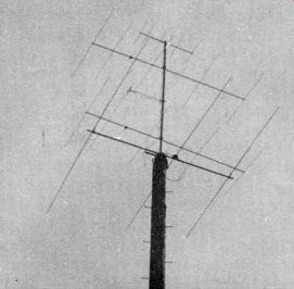
Fig. 165. Multi-Element "Yagi" Antennas.
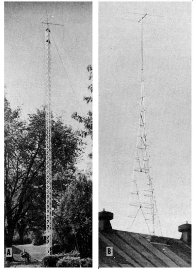
Fig. 166. Special High Tower Assemblies for Fringe Area Reception. (A) Courtesy
A-1 Radio Tower Co. Courtesy Wind Turbine Co.
Television reception at points beyond the radio horizon (see Figure 147) is not reliable, and for this reason many of the television manufacturers have restricted the sale of television receivers to are as in which reliable performance can be anticipated. However, the competitive nature of the radio business, as well as the intense public interest in television, is resulting in the sale of receivers in localities beyond the defined service area of transmitters. The Federal Communications Commission has granted higher power licenses to "rural stations" for service areas larger than metropolitan coverage. Long distance reception is being attempted with these stations. The radio service technician should realize that operation in these fringe areas cannot be guaranteed and is subject to the vagaries of transmission due to weather conditions and other effects, not completely understood. Extensive experimentation is being conducted in fringe areas and the following suggestions are offered for the experimentally minded technician:
1. Highly efficient antenna structures, such as four and five element arrays (see Figure 165), will assist in increasing the signal pick-up. Such arrays are used primarily for a single channel reception.
2. As shown in the nomograph of Figure 147, the radio horizon is increased by additional height at the receiving location. Towers for this purpose are commercially available.
Representative types are shown in Figure 166.
3. Television boosters can provide additional RF gain.
Care should be exercised to insure a sufficiently wide band for reception of the channel. The addition of the selectivity of a "booster" to that of the multi-element array may harm the quality of the received picture.
The band width may be restricted to such an extent that the sound channel suffers from attenuation or that picture quality is impaired.