by David Ranada

Camera and Picture Tubes
EXCEPT for a few high-end cultists, audio has abandoned the vacuum-tube technology that gave it birth. But in video the tube still reigns supreme; a vacuum tube is at the heart of nearly every video cam era and television or monitor screen. Scanning may be the core of video theory, but cathode-ray tubes are the foundation of video practice.
A basic understanding of how they apply the principle of scanning to image transmission should be part of every videophile’s education.
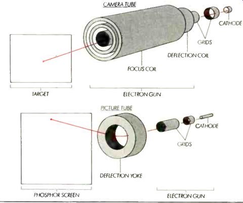
Despite their locations at opposite ends of the video chain, camera tubes and picture tubes are both cathode-ray tubes and are based on the principle of the electron gun (see illustration). In an electron gun, negatively charged electrons are "boiled" off a heated metal plate (the cathode), then pulled-not shot-toward the front of the tube by means of very strong electrostatic fields (the same kind of fields that create sparks between your fingers and doorknobs on dry days).
The fields are created by the application of very high positive volt ages to some of the tubes' internal parts. For example, the highest volt age in a picture tube occurs right at the phosphor screen; a large-screen color tube can have a charge of 30,000 volts-internally. The specially shaped electron-accelerating structures, called "grids," also serve as electrostatic lenses to focus the otherwise chaotically drifting electrons into a very tight beam, or a "cathode ray." The direction of electrons moving in a vacuum can be changed by magnetic fields in addition to electrostatic fields, and camera-tube electron beams are usually focused by means of magnetic fields. The magnetic fields are generated by coils surrounding the actual vacuum-tube portion of a camera tube.
With both types of tubes, electro magnetic coils are responsible for steering the beam in the required interlaced scanning pattern. About half the circuitry in a camera or monitor is devoted to generating the vertical and horizontal sweep signals that drive these deflection coils.
Picture-tube coils are mounted in a simple-looking assembly called a deflection yoke, the design and alignment of which is critical for picture quality, though it rarely receives attention in ads.
It's in what happens at the business end of the electron beam that the major differences between cam era and picture tubes really show up. In a camera, the beam hits a photosensitive target, on the other side of which has been focused the original optical image. The target is photoconductive; its electrical resistance at any point on its inner surface varies in proportion to the amount of light hitting its outer surface. Therefore, an electron beam sweeping over the target generates a varying voltage in the tube-output circuits. This voltage is proportion al to the light intensity on the target at the location of the beam, which is how the optical image is transduced into an electrical signal.
In contrast to the camera tube's photosensitive target, the inner front surface of a picture tube is coated with chemicals called phosphors that glow when struck by high-energy electrons. As the electron beam from the back of the tube sweeps over the phosphor coating, it produces a glowing spot. The intensity of the glow depends on the intensity of the beam. That intensity is controlled by the first grid the electrons pass on their way to the screen, and that grid is fed a signal originally generated by an electron beam in a camera tube. As the electron beam sweeps out its raster, an electrical signal is transformed back into an image.
For a concrete demonstration of part of this process, try this experiment to determine which end or side of a magnet is its north pole.
Simply hold the magnet up close to a monochrome picture tube while the set is on (do not do this experiment with a color set unless you know how to degauss a picture tube). The picture around the mag net will warp as the magnet's field deflects the electron beam. Areas where the picture twists clockwise are near the magnet's north (more properly, north-seeking) pole; counterclockwise warpage indicates the south pole. There are simpler ways to earn a merit badge in magnetics, but they aren't as high-tech!
========
Also see:
Source: Stereo Review (USA magazine)