The silicon controlled rectifier (SCR) is a 3-electrode device of the thyristor family, which can switch or control DC and rectify AC with controllable angle of conduction. Like the triac (Section 10). it has a separate gate (control) electrode; and like other thyristors, the SCR behaves in a manner analogous to that of the thyratron tube--even more so than does the triac.
Unlike the triac. the SCR can conduct in only one direction; its anode must be made positive and its cathode negative.
The SCR finds application principally in controlled rectification, and in inverters and control and switching circuits. It is used singly, in pairs or groups, and in conjunction with diacs, triacs. conventional transistors, unijunction transistors, or neon lamps. The ratings of SCRs cover a wide range, typical values being 1.7-amps to 35-amps and 100-volts to 700-volts.
Before working with SCRs. read the hints and precautions in Section 1.
SCR THEORY
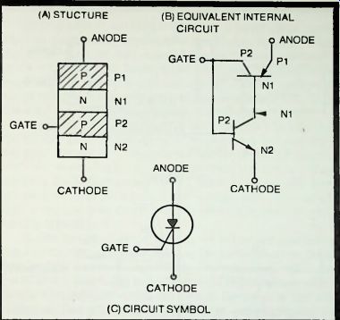
Fig. 11-1. Details of SCR.
The SCR is a 4-layer (PNPN) device; the arrangement of P and N layers within the pellet is shown in Fig. 11-1A. This PNPN arrangement is equivalent to an internally connected PNP transistor and NPN transistor, as shown by Fig. 11-1B. The circuit symbol for the SCR is given in Fig. 11-1C. The electrodes of the SCR are anode (normally positive biased), cathode (normally negative biased), and gate or control electrode.
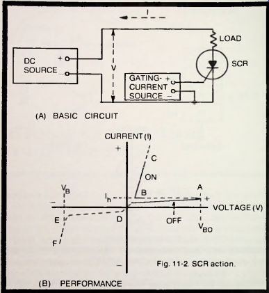
Fig. 11-2. SCR action.(A) BASIC CIRCUIT (B) PERFORMANCE
The basic SCR circuit is shown in Fig. 11-2A. Fig. 11-2B shows performance of the device. The SCR normally operates with anode positive, as shown here. If the anode is biased negative with respect to the cathode, only a small leakage current flows from D to E (as in a reverse-biased silicon diode).
When the reverse breakdown voltage--VB--is reached, however, a large, potentially destructive current flows, as from E to F and beyond. When the anode is properly positive, a very small leakage current flows (as from 0 to A); this is the off state of the SCR. When the anode voltage reaches the breakover voltage (Vbo ) at A, the current, due to avalanche breakdown, increases sharply (B to C and beyond); this is the on state of the SCR. The current at point Ih is the holding current. The breakover voltage (VBo) is determined by the value of the positive gating voltage applied to the gate electrode; the higher the gating voltage, the lower the breakover voltage, and vice versa. When the gate voltage is zero, the SCR blocks current in both directions (o/f state). From the curve in Fig. 11-2B. it is seen that the SCR snaps to its on state.
As in a thyratron tube, once conduction has been triggered in the SCR. the gate electrode-under ordinary conditions-exerts no further control of anode current until the anode-to-cathode is interrupted or temporarily reduced to zero, whereupon control is restored to the gate. Since the SCR, unlike the triac. is not a bidirectional device, it will cut off automatically and restore control to the gate at each reversal of the cycle when an AC voltage is applied to the anode (as in controlled rectification).
BASIC SCR SWITCHES
With a silicon controlled rectifier, a large anode current may be switched by means of a small gate current. Thus, a 5 mA gate current will switch 2.5 amps in a type 40810 SCR, and 8 mA will switch 35 amps in type 2N3650. The gate current can be obtained from any of a number of different sources, and many types of load devices can be operated by the SCR. This is the simplest application of silicon controlled rectifiers.
Figure 11-3 shows basic SCR static switches. In Fig. 11-3A, the IR122B SCR ( Q1) is operated from the 115-volt power line.
AC gate current is obtained from the line through resistors R1 and R2, accordingly, is in phase with the anode voltage.
Because the SCR is a rectifier, it conducts current only during the positive half-cycles of anode voltage, and it can conduct only when the gate current has reached a critical amplitude for that type of SCR.
In this circuit, if rheostat R1 is set so that the gate current reaches its critical trigger value at the instant that the positive half-cycle of anode voltage reaches its maximum value (90°), the SCR will fire at 90° and will remain in conduction-even if switch S1 is opened-until the end of the positive half-cycle (180°). At this point, the anode voltage being zero, the SCR switches off and remains off throughout the negative half-cycle (180° to 360°), since the SCR cannot conduct when its anode is negative.
During the succeeding positive half-cycle, however, the SCR is again triggered on at the 90° point (if the trigger voltage is still present at the gate) and conducts to the end of that half-cycle (180°). This performance is depicted by Fig. 11-3B, which shows that the anode current flows during the last half of each positive half-cycle. If R1 is set so that the gate current reaches its trigger value earlier in the AC half-cycle, then the SCR will switch on earlier and anode current will flow during a longer part of the positive half-cycle. In this AC circuit, once the SCR switches off. when the AC cycle passes through zero, control is restored to the gate.
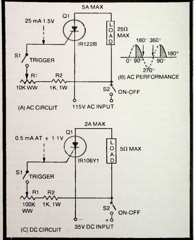
Fig. 11-3. Basic SCR switches.
In Fig. 11-3C. the IR106Y1 SCR ( Q1) is operated from a 35-volt DC source; otherwise, the circuit is of the same type as the one in Fig. 11-3A. In the DC circuit, if rheostat R1 is set so that the gate current has the critical trigger value required by that type of SCR, Q switches on when S is closed. The SCR then conducts anode current through the load and will remain on-even if S1 is opened-until the DC anode voltage is interrupted, as by momentarily opening switch S2. Thus, S2 always must be opened to reset the circuit to respond to subsequent trigger signals.
The advantage of the SCR switch, AC or DC, is that it allows a low current and voltage to be used to switch a much higher current and voltage. Thus, in Fig. 11-3A, a gate current of 25 mA at 1.5-volts switches 5-amps at 11-volts; and in Fig. 11-3C. 0.5 mA at 1.1-volts switches 2-amps at 35-volts. Various SCRs afford other levels of sensitivity and other maximum anode voltages and currents. Because of the comparatively low gate current and voltage, the contacts of the control switch, SI. may be light. Also. S1 need not be a switch per se, but may be light-duty relay contacts or in some applications a thermostat, photocell, thermocouple, humidity sensor, thermistor, or other similar device that will deliver a low DC voltage.
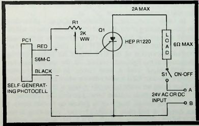
Fig. 11-4. Light-controlled SCR.
LIGHT-CONTROLLED SCR
Figure 11-4 shows how the DC output of a self-generating silicon photocell can supply the gate trigger current to an SCR. The type S6M-C photocell (PC1) delivers approximately 1.5 volts (at a maximum current of 8 mA) when actuated by 100 footcandles illumination, and this DC output will trigger the HEP R1220 SCR ( Q1) to a maximum of 2-amps anode current through the load. Either AC or DC supply may be used; with DC terminal A must be positive, and B negative. The photocell must be poled such that its positive DC output is applied to the SCR gate (see color coding in Fig. 11-4). To set up the circuit initially, illuminate the photocell and adjust rheostat R1 to the point at which the SCR switches on and passes current through the load. With DC supply, the photocell then will exert no further control until switch S1 is momentarily opened to restore control to the gate. With AC supply, however, control automatically returns to the gate each time the supply-voltage cycle passes through zero. This means that with AC supply the SCR will switch on each time that light is shined on the cell, and will switch off each time the light is interrupted; but with DC supply, the SCR will switch on each time the cell is illuminated and then will remain on when the light is removed.
This is a relatively simple arrangement, which is useful in many setups requiring a switch that closes on application of a light beam. While the circuit is not so sensitive as some similar ones, the self-generating photocell requires no bias supply, and this further simplifies the circuit. Insertion of the load device into the anode circuit of the SCR obviates the need for an auxiliary electromechanical relay. While a 2-amp SCR operated at 24 volts is shown here, the same circuit may be used with a heavier-current SCR and at higher anode voltage, provided the gate current for the new SCR is within the 8 mA output range of the photocell.
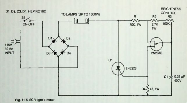
Fig. 11-5
SCR LIGHT DIMMER
The output of a silicon controlled rectifier can be varied smoothly by varying the phase of the gate trigger, with respect to the anode voltage. The earlier the trigger arrives in the positive half-cycle of anode voltage, the longer the anode current flows and. therefore, the greater its value. Conversely, when the trigger arrives late, anode current flows for a short time and its magnitude is low.
In Fig. 11-5. an adjustable RC-type phase-delay circuit--consisting of R2. R3, and C1--sets the time at which a 2N2646 unijunction transistor (Q2) delivers a gate trigger pulse to switch on the 2N3228 SCR (Q1). (See Section 5, for a detailed description of the UJT trigger for SCRs.) Through adjustment of the light-duty control, R3. the operator can vary the SCR output over a wide range. In the phase-control network, resistor R2 is a safety device which prevents rheostat R1 from being set to the full anode voltage of the UJT.
This principle is utilized here to control the brightness of incandescent lamps, singly or in groups up to 1000 watts. In this circuit, a full-wave bridge rectifier, consisting of four HEP R0162 silicon power diodes ( D1 to D4) supplies rectified power-line voltage to the SCR and lamp load. Because of the ...
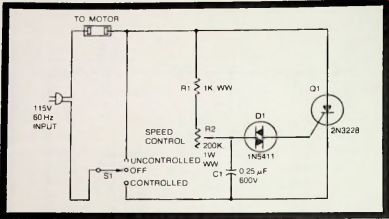
Fig. 11-6. SCR motor control.
... full-wave output of the bridge, the SCR is able to handle both half-cycles of the AC line voltage. The phase-shift network is frequency sensitive and has been designed for 60 Hz service (see Table 9-1 in Section 9 for details of this network).
The circuit will not work with fluorescent lamps and must not be connected to them.
The 2N3228 SCR shown in Fig. 11-5 is rated at 5-amps.
200-volts. but higher-powered SCRs may be substituted for heavier-duty service, and the 2N2646 portion of the circuit may be left intact. In addition to its intended use as a light dimmer, this circuit may be used also as a heater or oven controller.
SCR MOTOR CONTROL
Figure 11-6 shows a motor-speed-control circuit in which the output of a 2N3228 SCR (Q1) is controlled by adjusting the instant during the AC half-cycle at which a gate-trigger pulse arrives from a 1N5411 diac (DI) to trigger the SCR on. The earlier the trigger arrives in the positive half-cycle of SCR anode voltage, the longer the anode current flows until the end of the half-cycle, and the faster the motor runs. Conversely, the later the pulse arrives, the shorter the time of anode-current flow and the slower the motor runs.
This timing of the pulse results from adjustment of the phase-delay network (R1-R2-C1) in the diac circuit. In this network, the phase control is the 200,000-ohm, 1-watt, linear-taper, wirewound rheostat, R1 (Mallory Midgetrol or equivalent); and R1 is a safety resistor which prevents R2 from being set to the full anode voltage. (See Section 9, for a more detailed description of the phase-controlled-diac type of trigger circuit.) Because the phase-shift network is frequency sensitive, this motor-control circuit is recommended for 60 Hz service only. For operation at other frequencies, other values for R1, R2. and C1 will be required.
Since the SCR in this circuit passes only the positive half-cycles of AC supply voltage, the motor cannot be brought up to full speed. For full-speed operation, throw switch S1 to its uncontrolled position; this connects the motor directly across the power line without benefit of the SCR circuit. With S1 in its controlled position, the speed-control circuit is in operation.
The circuit is useful only with universal motors. With the 2N3228 SCR shown here, motors up to 1/4 horsepower can be controlled.
PHOTOELECTRIC BURGLAR ALARM
Battery-operated burglar alarms are very desirable, since they remain operable during power-line blackouts when house break-ins are very likely and in other times of power failure. It is important that the idling current of the device be low, so that one or two hotshot batteries will give long-time service in its operation. Two SCR-type burglar alarm circuits are included in this section; one (Fig. 11-7) employs a light beam; the other (Fig. 11-8) uses the familiar arrangement of closed "sensor" switches connected in series.
Figure 11-7 shows a photoelectric-type burglar alarm circuit which goes into operation when a light beam is interrupted, and continues to operate without break after the beam is restored. In this arrangement, a HEP R1103 SCR ( Q1) is triggered by the DC output of a CS120-C cadmium-sulfide photoconductive cell (PCI). The circuit leg, consisting of resistor R1 and the photocell, constitutes a voltage divider (operated from the 12-volt battery, B1) in which the cell acts as a light-controlled resistor. The output of the voltage divider is applied to the gate of the SCR.
When the cell is illuminated, its resistance is low, and the DC output of the voltage divider then is too low to trigger the SCR into conduction. But when the light beam is interrupted, as by an intruder, the dark resistance of the cell is very high and the output of the R1-PC1 voltage divider rises high enough to trigger the SCR on. The resulting flow of anode current through the bell causes the latter to go into operation. Once the SCR has thus been switched on, the gate loses control, and restoration of the light beam has no effect. The bell may be silenced only by momentarily opening the normally closed switch. S2 (installed at a secret location) which resets the circuit.
To set up the circuit initially, close switch S1 and illuminate the photocell, with R1 set to maximum resistance.
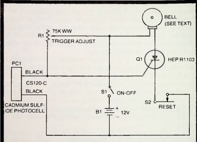
Fig. 11-7. Photoelectric burglar alarm
Then, darken the cell and adjust R1 to the point at which the bell starts ringing. Depress S2 to silence the bell. This is the correct operating point of the circuit, R1 requiring no subsequent adjustment. Note that the photocell has no exclusive output polarity (see identical color coding of its leads in Fig. 11-7). The bell must be a loud one able to operate efficiently on the SCR anode current (a satisfactory unit is Audiotex 30-9100). Aside from a bell, a siren, horn, or lamp also can be used.
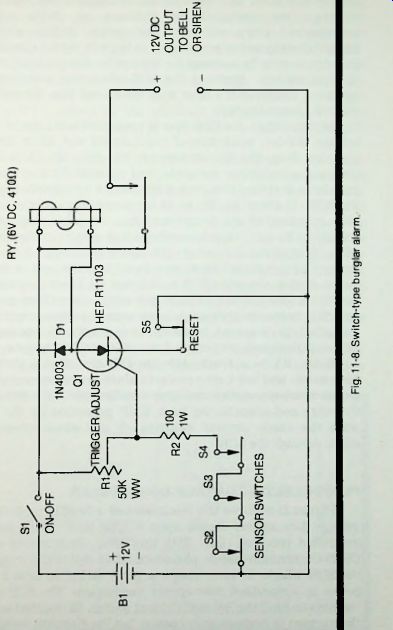
Fig. 11-8
SWITCH-TYPE BURGLAR ALARM
The circuit in Fig. 11-8 employs a series of normally closed switches (S2. S3. S4) the momentary opening of any one of which will trigger the HEP R1103 SCR (Q1) and close relay RY1 to operate a bell. horn, siren, or lamp. These "sensor" switches are installed on windows or doors where unauthorized entry will open the switch. A thin wire or metal-foil strip sometimes is used in lieu of a switch (breaking the wire or strip by opening the window has the same effect as opening switch). Because the SCR when once switched on stays on, reclosing the door or window (and thus the switch) will not silence the bell.
In this circuit, the SCR gate is connected to the output of a voltage divider, consisting of resistors R1 and R2 in series, operated from the 12-volt battery, B1. With S2. S3, and S4 closed, the divider is complete, and rheostat R1 may be set initially so that the DC output of the divider is too low to trigger the SCR. If either S2, S3, or S4 is opened, the lower resistor (R2) is cut out of the divider and then the gate signal, being limited by R1 only, rises to a voltage high enough to trigger the SCR. This closes the relay and connects 12 volts from the battery to the output terminals to actuate the bell or other alarm device. Once the SCR is switched on, it will continue to conduct anode current through the relay-even if the sensor switch is immediately closed-until normally closed switch S5 (installed at a secret location) is momentarily opened to interrupt the anode current and restore control to the gate.
Relay RY is a 6-volt. 410-ohm DC unit (Sigma 65F1 or equivalent) and has 1-amp contacts which are heavy enough to switch most alarm devices. The 1N4003 diode (D1) shunting the relay coil absorbs the back EMF generated by the coil when the anode current switches off and which otherwise might damage the SCR.
PHOTOELECTRIC GARAGE-DOOR OPENER
Figure 11-9 shows the electronics of a headlight-operated garage-door opener based upon a type HEP R1103 silicon controlled rectifier (Q1). With this setup, illumination of a CS120-C cadmium-sulfide photoconductive cell (PC1) triggers the SCR which, in turn, closes a relay (RY1) to switch AC power to a standard door-opener mechanism. The SCR then remains on until the normally closed switch, S2 (located inside the garage) is momentarily opened, but the disabling switch in the opener mechanism automatically removes the AC power from the mechanism when the door is fully open. To achieve reasonably foolproof service and to avoid accidental triggering by ambient light, the photocell must be provided with a suitable lens system and must be properly hooded so that only the bright light of high beams will actuate the circuit.
In this circuit, the photocell functions as a light-controlled variable resistor exhibiting very high resistance when darkened and low resistance when illuminated. A voltage divider is formed by the photocell and potentiometer R1 in series, and the DC output of this divider is applied to the gate of the SCR.
When the cell is darkened, the output is too low to affect the SCR. When the cell is illuminated, however, its resistance drops considerably, the output of the voltage divider rises, and the SCR is triggered on. closing the 6-volt, 410-ohm relay, RY1 (Sigma 65F or equivalent). When switch S2 subsequently is momentarily opened, the anode voltage is instantly removed from the SCR. and control is restored to the SCR gate. The 1N4003 diode (D1) shunting the relay coil absorbs the back EMF generated by the coil when the anode current switches off and which otherwise might damage the SCR.
To set the circuit initially, darken the photocell, turn potentiometer R1 down to its lowest point, and close switch S1. Next, illuminate the photocell with the headlights that will be used and with these lights spaced from the cell as they ...
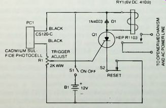
Fig. 11-9. Photoelectric garage-door opener.
... normally will be. Then, advance the setting of R1 to the point at which the relay just closes. This is the correct operating point of the circuit, and R1 will require no further adjustment except to compensate from time to time for drift and aging.
Finally, darken the photocell again, noting that the relay remains closed. Then, momentarily open switch S2, noting that the relay opens. Note that the photocell has no exclusive polarity; both leads are color-coded black, as shown in Fig. 11-9.
VARIABLE DC POWER SUPPLY (115 VOLTS)
Through phase control of the gate voltage, the DC output of an AC-operated SCR may be varied smoothly over a useful range. Figure 11-10 shows a half-wave rectifier circuit of this kind operated directly from the 115-volt AC power line. The average value of the DC output voltage of this circuit can be varied from close to zero to approximately 51 volts by adjustment of the light-duty 100.000-ohm rheostat, R2. The 2N3228 SCR (Q1) is rated at 5-amps, 200-volts. Because this is a half-wave circuit, substantial filtering of the DC output is required, and the resulting DC voltage may be higher than the maximum value given above, depending upon the type of filter used.
The sinusoidal gate signal is derived from the 2.5-volt center-tapped winding of transformer T1 (Stancor P-8629 or equivalent). The phase of this voltage is adjusted by means of an RC-type phase-shift network consisting of resistors R1 and R2 and capacitor C1.
When the gate-trigger value of this voltage is reached early in the anode-voltage positive half-cycle, anode current flows for a longer time (greater angle) during this half-cycle than when the trigger value is reached later. By appropriately adjusting 100,000-ohm rheostat R2, therefore, the operator can choose the phase delay that will result in minimum DC output, maximum DC output, or any point in between. The phase-delay network is frequency sensitive, so the R1, R2, and C1 values given here apply to 60 Hz only. (See Table 9-1, Section 9. for performance of this network.) Because this circuit, as presented in Fig. 11-10, is operated directly from the AC power line, safety precautions must be taken in some of its applications. For instance, if either the DC4- or DC- terminal is to be grounded, a 1:1 isolating transformer must be inserted between the power line and the input portion (S1-T1) of the circuit, to prevent electric shock or damage to the circuit or to the powered equipment.
The 2N3228 SCR is rated at 5 amps; however, higher-current units may be used in the same circuit for heavier-duty service, provided that their gate-voltage requirements are within the capability of the T-C1-R1-R2 gate-trigger circuit.
-----------
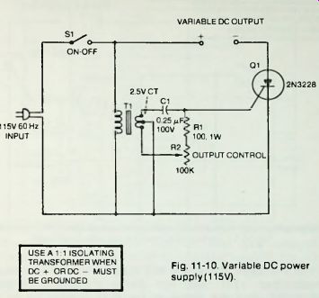
USE A 1:1 ISOLATING TRANSFORMER WHEN DC + OR DC - MUST BE GROUNDED
Fig. 11-10. Variable DC power supply(115V)-
-------------------
VARIABLE DC POWER SUPPLY (HIGH-VOLTAGE)
The variable DC power supply described in the preceding section is limited to the AC voltage of the power line. However, the same principle may be applied to a higher-voltage supply by adding a high-voltage transformer and substituting a higher-voltage SCR. The same delayed-phase gate-trigger circuit may be used as in the simpler circuit. Figure 11-11 shows how a suitable high-voltage transformer (T1) may be added to the original circuit.
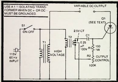
Fig. 11-11. Variable DC power supply (high-voltage). USE A 1:1 ISOLATING
TRANS
FORMER WHEN DC + OR DC - MUST BE GROUNDED
In Fig. 11-11. the SCR is still triggered by the low-voltage transformer (T2) and the same phase-shift network (C1-R1-R2), but the anode of the SCR is supplied by the secondary winding of transformer T1. Typical higher voltage SCRs are listed in Table 11-1. The average value of the unfiltered DC output voltage of the high-voltage circuit will be equal to approximately 0.45 times the rms value of the secondary voltage of transformer T1.
Because this circuit, like the earlier one, has a direct connection to the AC power line, special safety precautions must be taken in some of its applications. For instance, to prevent electric shock or damage to the circuit or to the powered equipment, if either the DC+ or DC- terminal is to be grounded, a 1:1 isolating transformer must be inserted between the power line and the input portion (S1-T1-T2) of the circuit.
-------
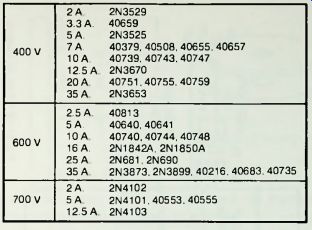
Table 11-1. Higher-Voltage SCRs
------------------------
DC-TO-AC INVERTER
Figure 11-12 shows the circuit of an SCR inverter which runs from a 12-volt battery and delivers 115-volts, 60-Hz AC at 100-watts continuous service and up to 150-watts intermittent service. SCRs give efficient performance in inverters. This circuit employs two 2N3650 SCRs in push-pull, each being triggered by a relaxation oscillator employing a 2N493 unijunction transistor (Q2 and Q3) and their associated frequency-determining networks (R4-R5-C1 and R6-C2). (See Section 5. for an explanation of the unijunction relaxation oscillator.) The 2N3650s are fast-turnoff SCRs recommended especially for inverter service. The upper UJT (Q2) operates at 120 Hz. and the lower one (Q3) at 60 Hz. Once rheostats R4 and R6 are set for these frequencies, they will not ordinarily need readjustment, hence may be provided with slotted shafts for screwdriver adjustment.
In circuits of this type, some means must be included for automatically switching off the SCRs at the proper time.
Ordinarily they will continue to conduct, once switched on, and there would consequently be no AC output from the circuit.
When this automatic switch-off is accomplished, the SCRs supply pulses alternately to the transformer, T1. This needed commutation is provided by capacitor C4 and inductor L1. As on SCR is switched on, C4 applies a negative voltage momentarily to the anode of the opposite SCR, switching the latter off.
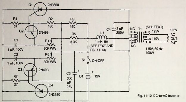
Fig. 11-12
-----------

Fig. 11-13. Details of inverter choke coil. IN BOBBIN. CLOSE WIND 196 TURNS NO. 16 ENAMELED WIRE (14 TURNS PER LAYER IN 14 LAYERS).
--------------
In general, construction of the inverter is straightforward.
T1 is a special inverter transformer (Triad TY-75A or equivalent). Choke inductor L1 is a 1-millihenry, 8-ampunit; and since such a heavy-current unit may not easily be located in commercial stocks, winding a simple one should be both economical and time saving. A suitable inductor may be made by close-winding 196 turns of No. 16 enameled wire in 14 layers at 14 turns per layer. Figure 11-13 shows details of a 1.5 in. diameter bobbin for this coil; the bobbin may be turned from wood and later impregnated with insulting varnish-or, if preferred, it can be made from some other dielectric material.
The SCRs should be heat-sinked, and the UJTs should be mounted in a cool part of the inverter assembly.
SOLID-STATE TIMER
Figure 11-14 shows the circuit of an all-solid-state timer based on a 2N3228 SCR (Q2) which will switch as high as 5 amps through a load device, such as a motor, actuator, heater, lamp, and so on. This is a delayed-make type of timer; that is, the SCR switches on at a selected instant after switch S1 has been closed. Setting of the 500,000-ohm rheostat, R2, allows selection of any interval between 0.1 and 50.1 seconds. While a 28-volt battery (B1) is shown here, a well-filtered, power-line-operated supply also can be used.
In this circuit, the SCR is triggered by a pulse from a 2N2419B unijunction transistor (Q1). The anode supply voltage of this UJT. which is also the DC voltage applied to the timing circuit (R1-R2-C1) is regulated by the 1N1777 zener diode (D1) and 200-ohm resistor (R4).
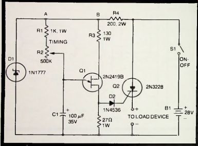
Fig. 11-14. Solid-state timer.
Operation of the circuit is simple: When switch S1 is closed, a regulated +12-volt DC potential is applied to the UJT anode circuit (point B) and the timing circuit (point A). Capacitor C1 then charges through resistors R1 and R2. the voltage across this capacitor increasing according to the time constant of the R1-R2-C1 circuit and thus according to the setting of rheostat R2. When the capacitor voltage eventually reaches the critical value of the UJT. Q1 fires and delivers a positive pulse which passes through steering diode D2 to the gate of the SCR. This triggers the SCR and causes it to conduct current through the load. The SCR then remains on until switch S1 subsequently is opened. Rheostat R2 may be provided with a dial reading directly in seconds on the basis of a calibration of the circuit.