The triac is a 3-electrode device of the thyristor family, which can switch either AC or DC. Unlike the diac ( Section 9), it has a separate control (gate) electrode which allows selection of the voltage level at which the triac begins to conduct. Like other thyristors, the triac behaves somewhat in the manner of the thyratron tube.
The triac finds application principally in control, switching, and trigger circuits. It is used singly or in conjunction with diacs, transistors, or silicon controlled rectifiers. The ratings of triacs cover a wide range, typical values being 100 volts to 600 volts and 0.5 amps to 40A.
Before working with triacs. read the hints and precautions in Section 1.
TRIAC THEORY
Figure 10-1A shows the basic internal structure of the triac, and Fig. 10-1B the circuit symbol. In this device, main terminals 1 and 2 are the output and common terminals, and the gate is the input or control terminal. Because of the series P and N layers in the triac pellet, this device-like the diac-can never pass current from terminal 1 to terminal 2 in the forward direction, regardless of the polarity of the applied voltage, but always behaves as a reverse-biased diode.
Figure 10-2 depicts performance of the triac. When a voltage is applied to this device, as from the main power source as shown in Fig. 10-2A, a very small leakage current flows (as from 0 to A, or 0 to D in Fig. 10-2B); this is the off state of the triac. As the voltage is increased, a critical value eventually is reached (VBo + in the positive direction, or Vbo " in the negative direction) at which avalanche breakdown occurs and a heavy current suddenly flows (B to C and beyond, or E to F and beyond); this is the on state of the triac. The breakover voltage (Vbo + or Vbo ') is determined by the amplitude of a positive or negative current pulse supplied to the gate electrode; the higher this amplitude, the lower the breakover voltage.
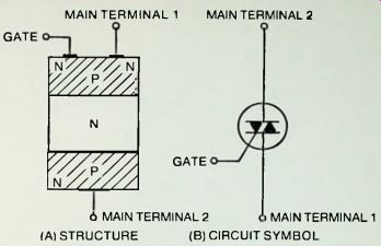
(A) STRUCTURE (B) CIRCUIT SYMBOL
Fig. 10-1 Details of triac.
Figure 10-2B shows that the triac snaps to its on state, positive or negative. As in a thyratron tube, once PC conduction has been initiated in the triac, the gate electrode under ordinary conditions exerts no further control until the voltage from terminal 1 to terminal 2 is interrupted or otherwise reduced to zero.
Unlike the diac, the triac has exclusive terminals which must not be interchanged. Thus, in the circuit diagrams in this section, Main Terminal 1 is labeled MT1, Main Terminal 2 is labeled MT2, and the gate is labeled G. The gate electrode is at the Main Terminal-1 end of the triac structure (see Fig. 10-1A) and is so indicated in the circuit symbol (see Fig. 10-1B and the circuit diagrams in this section).
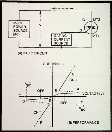
Fig. 10-2. Triac action.
Some Triacs may be worked harder than usual if a heat sink is provided for them. An immediate example is the triac motor control: In some instances, a 1/2-horsepower motor is the largest machine that can be accommodated by a certain control circuit; but if the triac is provided with a suitable heat sink, a 1/4-horsepower motor can be safely controlled.
For light dimmers, RCA advises that with small units built into the socket of the controlled lamp and handling up to 2 amps rms, sufficient heat sinking can be obtained from the lead wires to which the triac is attached. But up to 6 amps in a wall-mounted unit, the triac must be fastened to the metal wall box and face plate for sinking, and for still higher current, the face plate must be of a type that can be mounted clear of the wall for air flow underneath.
SIMPLE TRIAC SWITCH
In the simplest application of triac theory, an AC-powered triac may be turned off by removal of the gate current. In this way. a large AC current (amperes) can be switched on and off through a load by means of a very small gate current (milliamperes). The ratio of controlled power (a characteristic somewhat similar to power amplification) can have a value of several thousand to one. The load can be any device-such as a motor, lamp, or heater-operating within the current rating of the triac. that ordinarily would be operated by means of a switch, heavy-duty relay, high-current thermostat, or similar control.
Figure 10-3A shows the circuit of a simple switch employing a 2N5754 triac. The latter is rated at 2.5 amps, and a heavier-duty triac may be used in its place if higher-current operation is desired. The adjustable trigger current is supplied by the resistance combination R1-R2 connected back to the supply voltage. Rheostat R1 is a 200,000-ohm, 1-watt, linear-taper unit (Mallory Midgetrol or equivalent). Fixed resistor R2 protects the rheostat from direct connection to the high voltage. Normally open switch S2 (SPST) is the triggering device. Instead of a simple switch, however, the light-duty contacts of a sensitive relay, a photoconductive cell, or a temperature sensor might be used. Closing the contacts or reducing the resistance of the sensor passes approximately 10 mA into the triac gate section and switches the triac on to pass up to 2.5 amps through the load.
Figure 10-3B depicts operation of the circuit. The plot shows the angle of start and the duration of main current flow.
Because of the simple resistive control circuit, the gate current is in phase with the triac voltage. When the gate current is low at the beginning of the AC cycle, however, the triac acts as a very high resistance and virtually no current flows through the load.
When R1 is appropriately set for a given triac and AC voltage, the gate current reaches the trigger value for the 2N5754 when the supply voltage is at the maximum point in the cycle, and the triac is abruptly switched on. Conduction then continues until the end of the positive half-cycle, whereupon Q1 switches off as the supply-voltage cycle passes through zero, and remains off until the maximum-voltage point in the negative half-cycle is reached. At that point. Q1 again switches on and remains on until the zero point at the end of the cycle.
Thus, the trigger voltage and current determine the instant at which the triac is switched on and the interval of current flow through the load, in this instance the flow being from 90° to 180° and from 270° to 360°.
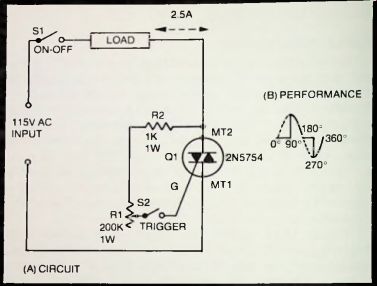
Fig. 10-3. Simple triac switch.
If rheostat R1 is adjusted to a lower resistance, the trigger-voltage value will be reached earlier in the cycle and the load current will flow for a greater part of each half-cycle.
This is essentially an off-on circuit and might invite the question of why it should be used in lieu of a simple switch, such as S1. The answer is that a switch such as S1 must handle the full 2.5 amps, whereas S2 (in whatever form) need handle only a few milliamperes. Any pair of light-duty contacts-or equivalent device-can serve as S2.
GENERAL-PURPOSE CONTROLLER
Figure 10-4 shows the circuit of an AC controller which, though very small by comparison, may be used in the manner of a Variac to adjust the AC input to any device connected to the load socket that is capable of control by a triac. The 40429 triac shown here provides a maximum output current of 6 amps and may be operated up to 200 volts. The range of control, from maximum output to very nearly complete cutoff, is provided by a simple, volume-control-type rheostat (R1).
The triac is triggered by means of a 40583 diac (D1) operated from a "tuned" phase-shift network. R1C1. (See Section 9 for a general discussion of the diac trigger circuit.) The point in the AC supply-voltage cycle at which the diac triggers the triac is determined by the setting of R1 which, in turn, adjusts the phase of the trigger with respect to that of the supply voltage.
In this way. the rheostat setting determines the angle of flow and consequently the output current (once the triac has been triggered, output current continues to flow until the end of that half-cycle, and is retriggered at the corresponding point in the succeeding half-cycle: See Fig. 10-3B). The lower the resistance setting of R1, the higher the output current of the circuit.
Because no practical capacitor (C1) can give the full 90° phase shift attributed to capacitance, the phase shift of the R1C1 network is never sufficient to cut the triac completely off: nevertheless, the control range is wide and very useful.
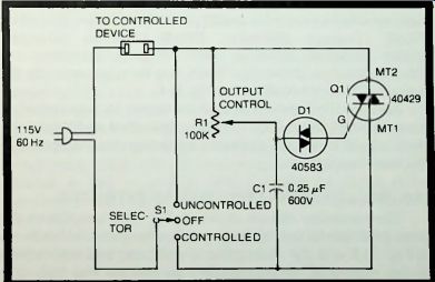
Fig. 10-4. General-purpose controller.
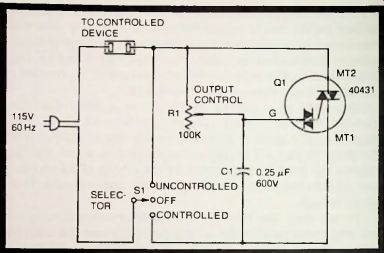
Fig. 10-5. Controller using combination thyristor.
For complete turn-on and turn-off. switch S1 acts as a mode selector. In the uncontrolled position of this switch, the full line voltage is applied to the load without benefit of the controller circuit which then stands idle. With S1 in the controlled position, the load is supplied with adjustable current delivered by the triac. With S1 in its off position, the load is deenergized.
For heavier-duty service than that afforded by the 6-amp triac shown in Fig. 10-4. higher-powered triacs are available.
Representative examples are Types 40668 (8-amps, 200-volts), 2N5567 (10-amps. 200-volts), 2N5568 (10-amps, 400-volts), 2N5571 (15-amps, 200-volts), 40707 (30-amps, 200-volts). and 2N5444 (40-amps, 200-volts). Each may be triggered with the same R1C1D1 circuit shown in Fig. 10-4.
Some of the familiar uses of the circuit include control of lamps (except fluorescent), motors (universal and induction), electric heater or oven elements, soldering irons, AC-powered electronic apparatus.
CONTROLLER USING COMBINATION THYRISTOR
The controller circuit shown in Fig. 10-5 operates on the same principle as that of the general-purpose controller shown in Fig. 10-4. and the description of operation and applications in the preceding section applies as well to Fig. 10-5. The difference is that the latter circuit employs a 40431 combination thyristor (Q1) which contains both the diac and triac units. This combination unit somewhat simplifies assembly, wiring, and replacement.
The 40431 thyristor is rated at 6-amps. 200-volts. A similar unit-Type 40432-is rated at 6A. 400V. Type HEP R1725 is equivalent to 40431. and HEP S0015 is equivalent to 40432. All may be operated with either resistive or inductive loads.
DC-CONTROLLED SOLID-STATE AC RELAY
In electrical and electronic installations, it is often necessary to switch high AC voltage and current with a low-current DC control signal. At least two electromechanical relays operating in cascade usually are required for this purpose, since the contacts of a sensitive (low-voltage, low-current) DC relay cannot handle the high AC current.
For this application, an all solid-state relay circuit-with no moving parts whatever-may be achieved with a suitable triac. since a triac may be switched with a DC gate trigger of either polarity and requires only a few milliamperes to switch several amperes.
Figure 10-6 shows such a circuit. The 40773 triac ( Q1) shown here is rated at 2.5-amps. 200-volts. A similar unit--Type 40774--is rated at 2.5-amps, 400-volts. In this arrangement, the triac is triggered on by a DC gate voltage (1.5 to 2 volts at 20 milliamperes) applied to the DC control-signal input terminals. The trigger-voltage and current values may differ somewhat from these figures with individual triacs.
Once the triac has switched on. it will continue to conduct for the remainder of the AC half-cycle, extinguishing as the supply-voltage cycle crosses the zero line, and retriggering at the corresponding point in the succeeding half-cycle. AC will continue to flow through the load as long as the DC control signal is present at the gate, and will cease when the DC is interrupted. While the DC control-signal input terminals are labeled 4- and - in Fig. 10-6, the polarity shown is not mandatory; the triac triggers on either a positive or a negative gate voltage.
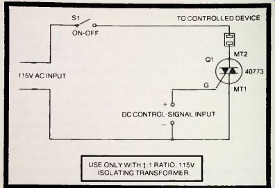
Fig. 10-6 DC-controlled solid-state AC relay.
This relay circuit allows 2.5 amps at 115-volts AC to be switched with approximately 20 mA at 1.5-2 volts DC. This represents a current-control ratio of 9583:1 when the DC control voltage is 1.5. For increased sensitivity, a transistor or IC direct-current amplifier may be operated between a millivolt/microampere type of DC signal source and the DC control-signal input terminals (see. for example. Fig. 10-7).
Because this type of relay circuit is often operated from an external DC signal source which must be returned to main terminal 1 of the triac as shown in Fig. 10-6, this source will automatically be connected dangerously to one side of the AC power line. Therefore, to avoid electric shock or damage to the equipment, it is advisable to insert a 1.1 isolating transformer between the power line and the circuit in Fig. 10-6.
When this solid-state relay must switch higher current than the 2.5-amp rating of the 40773 triac, employ a heavier-duty triac at Q1. Higher-current triacs include Types 40733 (4.2-amps. 200-volts). 40429 ( 6-amps. 200-volts). 40668 (8-amps. 200-volts). 2N5567 (10-amps. 200-volts), 40662 (30-amps. 200-volts). and40688 (40-amps. 200-volts).
USE ONLY WITH 1 RATIO, 115V ISOLATING TRANSFORMER
SENSITIVE DC-CONTROLLED TRIAC SWITCH
Figure 10-7 shows an all solid-state circuit that can switch 0.5 ampere at 115-volts AC in response to a DC control signal of 47 al A at 1.5-volts. This performance represents a cur- rent-control ratio of 10,638:1, and a power-control ratio of 815,603:1.
In this circuit, the DC control signal is amplified by a single-stage DC amplifier based upon the 2N2716 silicon bipolar transistor (Q1) to an output current of 10 mA which is applied as a gate current to trigger the 40769 triac (Q2) into conduction. The triac conducts AC through the load as long as the DC is present at the DC control-signed input terminals, and ceases when the DC is interrupted. The 2N2716 provides very low-drift operation, insuring against self-triggering of the circuit.
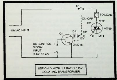
Fig. 10-7. Sensitive, DC-controlled triac switch. USE ONLY WITH 1:1 RATIO, 115V
ISOLATING TRANSFORMER.
With individual transistors and triacs, the DC signal requirement may differ somewhat from the 1.5-volts and 47 uA indicated in Fig. 10-7. The DC control signal can be obtained from a rectifying diode, self-generating photocell, photo- conductive cell, thermocouple, light-duty contacts making and breaking a 47 uA input current, and so on.
The floating 12-volt transistor DC supply (B1) is shown here as a battery, and a small battery will be preferred in many installations; however, a well-filtered, power-line- operated supply may be used instead. This type of relay circuit is often operated from an external DC signal source which must be returned to the emitter of the transistor and main terminal 1 of the triac. as shown in Fig. 10-7. The source thus will be automatically connected dangerously to one side of the AC power line. Therefore, to avoid electric shock or damage to the equipment, it is advisable to insert a 1:1 isolating transformer between the power line and the circuit in Fig. 10-7.
When this solid-state relay must switch higher current than the 0.5-amp rating of the 40769 triac, use a heavier-duty triac at Q2. Higher-current triacs include types 40767 (1.6-amps. 100-volts). 40509 (2.5-amps. 200-volts). 40733 (6-amps. 200-volts), 40668 (10-amps. 200-volts). 2N5571 (2.2-amps, 200-volts), 40691 (4.2-amps, 200-volts), 40429 (8-amps, 200-volts), 2N5567 (15-amps, 200-volts), 40662 (30-amps. 200-volts). and 40688 (40-amps. 200-volts).
For use with negative control voltage, substitute a PNP transistor for the 2N2716. and reverse both B1 and the DC control-signal input terminals.
MOTOR CONTROLS
Diac/triac circuits are very popular for controlling the speed of electric motors. The circuits given in Fig. 10-4 and 10-5 are ideal for this purpose. As the resistance setting of rheostat R1 in each of these circuits is reduced, the angle of conduction of the triac increases and so does the motor speed.
These circuits will not operate satisfactorily with motors of the capacitor-start, synchronous, repulsion-induction, and shaded-pole types, but are entirely useful with universal and induction motors. Both circuits will handle motors rated up to 3/4 horsepower.
LIGHT DIMMERS
One familiar application of the diac/triac AC controller is the continuously variable adjustment of the brightness of incandescent lamps. This function, called light dimming, can be performed by any of the common circuits, such as Figs. 10-4 and 10-5. However, each of these simpler circuits exhibits a hysteresis effect which can be troublesome in some installations; that is. the controlled lamp switches on at a particular setting of the control rheostat when the latter is being turned up. but switches off at a somewhat different setting when the rheostat is being turned down.
This hysteresis can be reduced by employing two RC timing circuits in cascade, in place of the single circuit (R1-C1) in Figs. 10-4 and 10-5, an arrangement which provides two time constants. This improvement is shown in the light-dimmer circuits in Figs. 10-8 and 10-9. In each of these arrangements, adapted from a basic RCA circuit, the first timing leg is R2-C2. and the second leg is R3-C3.
During triggering, capacitor C3 discharges into the triac gate: but C2. being charged to a higher voltage than is C3 and having a longer discharge time, is able to replenish the C3 charge to some extent, and this reduces the hysteresis and extends the adjustment range of dimmer-control rheostat R2.
The rheostat is a 200,000-ohm, 1-watt, linear-taper unit (Mallory Midgetrol or equivalent).
The two improved circuits are functionally identical.
However, Fig. 10-8 employs a separate triac (type IRT82) and diac (type IRD54-C), whereas Fig. 10-9 employs a single thyristor (type 40431) which incorporates both diac and triac in the same package. Where needed, the latter arrangement somewhat simplifies construction, wiring, and replacement.
The circuit given in Fig. 10-8 may be used in either 115- or 220-volt service (up to 6 amps). The circuit in Fig. 10-9 is intended solely for 115-volt service, but may be modified for 220-volt service by substituting a type 40432 unit for 40431.
A further refinement in the improved light-dimmer circuits is the inclusion of a low-pass filter (L1-C1) to suppress radio/TV interference which might otherwise result from the rapid triggering of the triac. This filter requires a high-current (5-amp) 100 u-H inductor of the smallest obtainable size (Dale IH5-100 or equivalent).
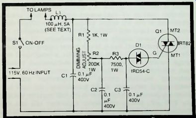
Fig. 10-8. Improved light dimmer No. 1.
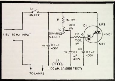
Fig. 10-9. Improved light dimmer No. 2.
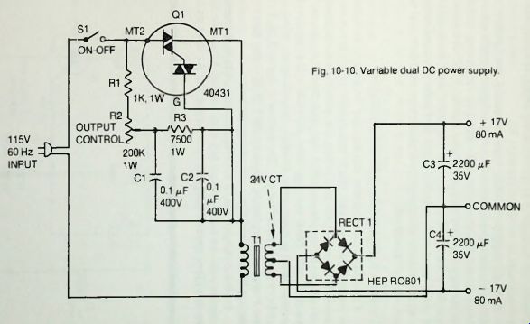
Fig. 10-10.
VARIABLE DUAL DC POWER SUPPLY
In Fig. 10-10. a continuously variable, dual-output, DC power supply is obtained by using a triggered triac AC controller to vary the primary current of the power transformer, T1. The circuit delivers two separate maximum DC voltages: 4-17-volts and -17-volts, each at a maximum of 80 mA. The controller employs a type 40431 combination thyristor. Q1 (diac and triac in the same package), and its circuit is similar to the one in Fig. 10-9. Rheostat R2 in the controller section of the power supply permits smooth adjustment of the DC output voltage, and is a 200,000-ohm, 1-watt. linear-taper unit (Mallory Midgetrol or equivalent).
In the power supply section, transformer T1 (Stancor P-6377 or equivalent) has a 24-volt center-tapped secondary.
The rectifier, RECTI (type HEP R0801), although built as a bridge rectifier, is not used as a bridge in this circuit. Instead, each two-diode half of the rectifier provides a full-wave, center-tap rectifier circuit in conjunction with the center-tapped secondary of the transformer, the right half delivering positive voltage, and the left half negative voltage.
The 2200 uF, 35-volt electrolytic capacitors (C3 and C4) provide adequate filtering for most low-current service. At low output-current drain, these capacitors charge to very nearly the peak value of the 12-volt half-secondary voltage of the transformer, that is, to approximately 17 volts. At higher currents, the voltage is proportionately lower, but may easily be readjusted by means of rheostat R2.
A dual supply of this type is useful for generating adjustable plus and minus DC voltages for integrated circuits during circuit development and circuit or IC testing, and for similar applications requiring two identical DC voltages of opposite polarity. The same arrangement may be employed for other maximum output voltage and current values simply by appropriately changing the transformer, rectifier, and two electrolytic capacitors.
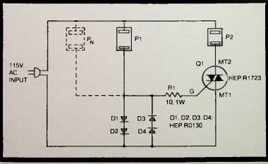
Fig. 10-11. Automatic equipment power switch.
AUTOMATIC EQUIPMENT POWER SWITCH
Figure 10-11 shows how a triac may be used to switch off the power to a main unit (such as a master amplifier or main transmitter) automatically when the power to an auxiliary unit (such as a preamplifier or modulator) is manually switched off. This arrangement forestalls the accidental leaving on of a main unit, through forgetfulness, when the auxiliary unit is switched off. The method is due to T. N. Tyler (see Popular Electronics, January 1973, p. 52), and has been adapted here for readily available components.
In this arrangement, a HEP R1723 triac (Q1) is connected in series with the main-unit socket (P2) and the AC power line.
The auxiliary unit is plugged into socket P1. As long as the auxiliary unit is operating, it draws its power through diodes D1 to D4. developing a voltage drop across these diodes; and this voltage triggers the triac on. allowing the main unit to receive power.
When later, the auxiliary unit is switched off, the diode voltage drop disappears, the triac switches off. and the main unit likewise is switched off even though its switch may absent-mindedly have been left on. If more than one auxiliary unit is used, separate sockets for them-such as PN-may be connected in parallel with P1 and P2.
This "equipment minder'' works well when the plugged-in units contain no reactive paths which can draw significant current through the diodes even when the units are manually switched off. Such a reactive path might be provided by a large suppressor capacitor connected across the power-line-input terminals inside the unit. The resulting capacitor current would maintain a voltage drop across the diodes and this would keep the main unit running in defeat of the whole idea. In some instances-but not all-such capacitors may be removed without degrading performance of the equipment.
The HEP R1723 triac shown in Fig. 10-11 is a 6-amp, 200-volt unit. A heavier-duty triac may be selected for higher power drain by the main unit.