The diac is a comparatively simple switching device of the thyristor family, in which the semiconductor contains three layers, as in a PNP transistor. Connections are made only to the two outer layers, so the diac has only two terminals and it operates on either AC or DC, conducting in either direction. Like other thyristors, the diac behaves somewhat in the manner of a thyratron tube.
The diac finds application principally in control, switching, and trigger circuits where a bidirectional, 2-terminal switching device is advantageous. It may be used by itself or in conjunction with a triac or a silicon controlled rectifier.
Before working with diacs, read the hints and precautions in Section 1.
DIAC Theory
Figure 94(A) shows the basic structure of the diac, and Fig. 94(B) the circuit symbol. In this device, the doping concentration, unlike that of the junction transistor, is the same for both junctions, and this enables symmetrical operation. Neither terminal is exclusively anode or cathode.
Because of the series arrangement of P and N layers inside the device, the diac can never conduct in the forward direction, but always behaves as a reverse-biased avalanche diode, regardless of the direction of an applied voltage.
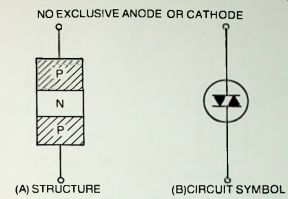
Fig. 9-1. Details of diac.
Figure 9-2 illustrates behavior of the diac. When a voltage is applied to the device, as in Fig. 9-2(A), a very small leakage current flows; this is the off state of the diac. As the voltage is increased, a critical value termed the breakover voltage eventually is reached (Vbo+ when the voltage is positive, Vbo- when it is negative) and at this point avalanche breakdown occurs and a heavy current suddenly flows; this is the on state of the diac. Once the diac is thus switched on by a positive or a negative voltage, the device will continue to conduct current until the voltage is removed or reduced to zero.
Figure 9-2(B) depicts diac action. Here, a small leakage current (Ibo+ for a positive voltage, or Ibo" for a negative voltage) flows until the applied voltage reaches the breakover value (VBo+ or Vbo-. as the case may be). When the breakover voltage is reached, the current increases sharply, as from I+ or I-. A negative-resistance effect sets in-as shown by the backward bend of the curve--and consequently the current increases as the applied voltage is subsequently decreased.
At this writing, the principal use of the diac is to supply a trigger pulse to a triac, and this application is illustrated in a number of ways in Section 10. However, the triggered response of the diac itself and the bilateral conduction of this device also suit it to certain applications other than triac operation. Several of these are described in this section and possibly will suggest still others to the experimenter.
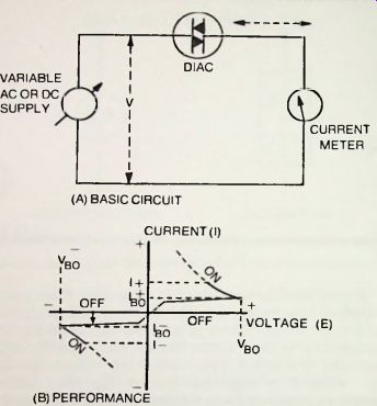
Fig. 9-2. Diac action.
AMPLITUDE-SENSITIVE switch
The simplest application of the diac by itself is automatic switching. A diac appears to either AC or DC as a high resistance (almost an open circuit) until the impressed voltage reaches the critical Vbo value. The diac conducts when this value is reached or exceeded. Thus, this simple 2-terminal device may be switched on simply by raising the amplitude of the applied control voltage, and it will continue to conduct until the voltage has been reduced to zero.
Figure 9-3 shows a simple amplitude-sensitive switch circuit employing a 1N5411 diac. An applied voltage of 35 volts DC or peak AC will switch the diac into conduction, whereupon it will pass a current of approximately 14 mA through the output resistor. R2. Individual diacs may switch on at voltages lower than 35 volts. With 14 mA on current, the output voltage developed across the 1000-ohm resistor will be 14 volts. If the voltage source has an internal conductive path in its output circuit, resistor R1 may be omitted.
In operating the circuit, adjust the input voltage upward slowly from zero while monitoring the output. Up to approximately 30 volts, there will be little or no output voltage, owing to the very low leakage current of the diac. At approximately 35 volts, however, the diac will suddenly break down and an output voltage will appear across resistor R2.
Reduce the input voltage, and note that the output voltage also decreases, eventually reaching zero when the input voltage is zero. At zero, the diac is "extinguished." and is in condition to be triggered again by the 35-volt amplitude.
STATIC DC SWITCH
The simple switch described in the preceding section may be triggered also by means of a change in voltage. Thus, a steady voltage of say 30 volts may be applied continuously to the 1N5411 diac without conduction taking place; but if an additional voltage of say 5 volts is added in series, the breakdown voltage of 35-volts is reached and the diac "fires." Removal of the 5-volt "signal" then will have no effect on the conduction which will continue until the 30-volt supply voltage is reduced to zero. This behavior is somewhat similar to that of a thyratron tube, but in this instance is obtained with the simple 2-terminal diac.
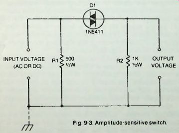
Fig. 9-3. Amplitude-sensitive switch.
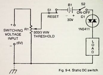
Fig. 9-4. Static DC switch.
Figure 9-4 shows a switching circuit employing the principle of incremental-voltage switching described above. In this arrangement, a 30-volt bias is applied to the 1N5411 diac (D1) by the supply B1 (while a battery is shown here for simplicity, the 30 volts can be supplied by any other source of steady DC). With this voltage, the diac does not conduct, and no current flows through the external load.
When the input voltage is applied through potentiometer R1. however, the increase in voltage is sufficient to switch the diac on, and current is delivered to the load. Once conduction is thus initiated, the control voltage has no further effect.
Operating the reset switch, S, temporarily interrupts the 30-volt supply and restores control to the switching voltage.
Most 1N5411S will be able to idle at 30 volts without self-firing. However, an individual unit may require a lower bias voltage. Similarly, most units will fire with the 6-volt increment shown in Fig. 9-4, but more sensitive units will operate with a smaller switching voltage which may easily be selected by means of the 500-ohm wirewound potentiometer, R1.
The maximum load resistance recommended for use in this circuit is 1000 ohms. The load current at this resistance is approximately 14.3 milliamperes.
This circuit will find use wherever a simple electrical latching action is desired without the complexity of 3-element thyristors and where the current demand is not severe.
Individual diacs show surprising sensitivity in this simple arrangement.
ELECTRICALLY LATCHED RELAY
Figure 9-5 shows the circuit of a DC relay that will remain closed (latched) once it has been actuated by a control signal, and has the dependability of a mechanically latched relay.
This circuit employs the principle described in the preceding section; that is, the IRD54-C diac here is biased at 30 volts, a potential too low for conduction. But when a 6-volt increment is applied to the diac, the latter passes current which picks up the relay (the diac then continues to conduct, holding in the relay, although the 6-volt control voltage ceases).
In this circuit, most IRD54-Cs will be able to idle at 30 volts without self-firing; however, an individual unit may require a lower voltage. Similarly, most units will fire readily with the 6-volt increment (control signal) shown in Fig. 9-5, but more sensitive units will operate with a lower control voltage which may easily be selected by means of the 500-ohm wirewound potentiometer, R1.
In its on state, the diac passes a current of 2 mA. The relay (RY1) is a 1 mA, 1000-ohm unit, so the extra 1 milliampere is diverted through resistor R2. Since the latter is a wirewound rheostat, it can be adjusted-along with potentiometer R1--for desired sensitivity of response.
While a 6-volt potential is required in series with the 30-volt bias to switch on the diac, a higher-voltage control signal may be employed, and R1 adjusted for the 6-volt value. The 30-volt supply is shown here as a battery, for simplicity, but can be any well-filtered DC source.
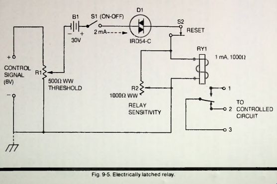
Fig. 9-5
When R1 and R2 are properly set, the relay picks up readily when the control signal is applied to the input terminals of the circuit. Then, the relay continues to hold even when the control signal is removed, and holds until the reset switch, S2, is depressed momentarily. The relay is a 1 mA, 1000-ohm unit (Sigma 5F or equivalent) having %-ampere contacts. Use terminals 1 and 3 when the external circuit must be closed by relay closure; use 2 and 3 when the external circuit must be opened. If the 1/4-ampere contact rating is too low for the power to be handled in the controlled circuit, a higher-wattage auxiliary relay may be operated from this circuit.
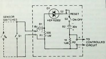
Fig. 9-6. Latching sensor circuit.
LATCHING SENSOR CIRCUIT
Some systems, such as burglar alarms and process controllers, require an actuating signal that remains on after it has been initiated and ceases only when operation is reset from a central control point. Once available, this signal can be used to drive circuitry for alarms, recorders, shutoff valves, safety devices, and so on.
Figure 9-6 shows a circuit of this type. Here, a HEP R2002 diac is the switching device. In this arrangement, the diac idles at 30 volts, supplied by B2. and passes such a low current that virtually no voltage appears across the 1000-ohm output resistor, R2. However, closure of switch SI, which may be a "sensor" on a door or window, adds 6 volts (from B1), to the 30-volt bias, and the resulting 35 volts fire the diac and produce approximately 1-volt output across R2. The diac then remains on in spite of any subsequent opening of S1 (as by closing of the door or window) until the reset switch (S2, at a secret location) is temporarily opened. Any number of "sensor" switches, such as Sn. may be operated in parallel, but this system requires that switches close when actuated, whereas the common burglar alarm system requires that they open.
While batteries are shown for simplicity, both the B1 and B2 voltages may be obtained from any other source of well-filtered DC. The 30 volts may be obtained with any convenient combination of batteries (one selection is two 15-volt units: Eveready 417. or equivalent).
For output voltage of the opposite polarity, simply reverse the connections to B1 and B2; the diac, being bilateral, requires no reversal.
DC OVERLOAD CIRCUIT BREAKER
Figure 9-7 shows a circuit that automatically disconnects a load device from its power supply when the DC operating voltage exceeds a predetermined value. The device then remains disconnected until the voltage is reduced and the circuit is reset.
In this arrangement, employing an IRD54-C diac and 2N2712 silicon bipolar transistor, the diac (D1) is normally in its off state, and the static current of the transistor (Q1) is too tiny to actuate the sensitive relay (RY1). When the power supply voltage exceeds a critical value determined by the setting of potentiometer R1. the diac switches on and its DC output is applied to the transistor through potentiometer R2.
The resulting increase in collector current actuates the relay which then opens the lead between the power supply and load.
The diac then remains on and the relay actuated until the voltage returns to normal and the reset switch, S1. temporarily is opened.
To adjust the circuit initially, adjust potentiometers R1 and R2 so that the relay just operates when the power-supply voltage reaches the selected critical value. The relay then should remain actuated until the voltage falls back to its normal level and the reset switch is temporarily opened. When the circuit is operating correctly, the "firing" voltage at the diac input should be approximately 35 volts (individual diacs may switch on at a lower voltage, but this can be accommodated by adjustment of potentiometer R), and the DC voltage at the base of the transistor should be approximately 0.57 volt (at approximately 12.5 u-A). Individual transistors may require higher or lower voltage here, but this can be accommodated by means of potentiometer R2.
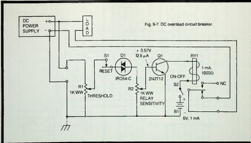
Fig. 9-7
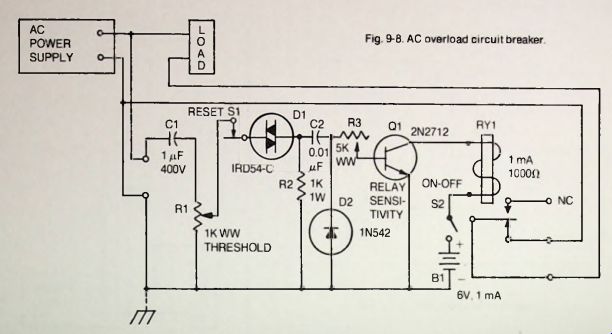
Fig. 9-8
The relay is a 1 mA. 1000-ohm unit (Sigma 5F, or equivalent). As shown in the diagram, only two of the relay contacts are used, giving the relay a normally closed status.
The relay contacts are rated 1/4-watt; for higher power service, relay RY 1 can actuate an auxiliary heavier duty unit.
PHASE-CONTROLLED TRIGGER CIRCUIT
As mentioned earlier, the principal use of the diac at present is to supply a trigger voltage to a triac in various control circuits. The diac circuit for this purpose is phase controlled and by itself can find use in other applications than triac control, where a phase-adjustable pulse output is needed.
Figure 9-9 shows the classic diac trigger circuit.
AC OVERLOAD CIRCUIT BREAKER
Figure 9-8 shows the circuit of an AC overload circuit breaker. This circuit performs in the same manner as the DC arrangement described in the preceding section, and may be read for the general description of operation and performance.
The AC circuit differs from the DC circuit in the addition of blocking capacitors C1 and C2 and diode rectifier D2; also, the relay sensitivity control in the AC circuit is the 5000-ohm wirewound rheostat (R3) instead of the 1000-ohm potentiometer (R2) in the DC circuit.
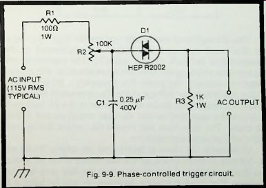
Fig. 9-9. Phase-controlled trigger circuit.
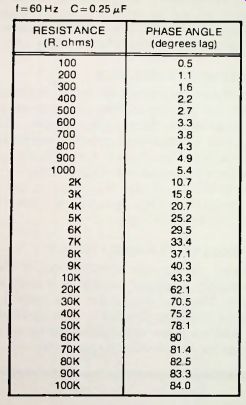
Table 9-1. Phase Angles For Various Resistances When C = 0.25 uF
This arrangement essentially controls the angle of firing of the diac, and this is accomplished by adjustment of the phase-control network (R1-R2 and C1). The resistance and capacitance values given here are representative. For a given frequency (usually the power-line frequency). R2 is adjusted so that the breakover voltage of the diac is reached at the time instant corresponding to the desired point in the AC half-cycle at which the user desires that the diac switch on and deliver the pulse. The diac then will repeat this action during each half-cycle, positive and negative.
Ultimately, the phase is determined not only by R1-R2 and C1. but also to some extent by the impedance of the AC source and the impedance of the circuit which the diac arrangement triggers. For most purposes, however, it will be helpful to examine the phase of the diac-circuit resistance and capacitance to determine performance of the circuit.
Table 9-1, for example, shows the phase angles corresponding to various settings of the resistance against the 0.25 u-F capacitance in Fig. 9-9. The data are given for 60 Hz, the frequency at which the diac trigger circuit is so often used. Note from these data that as the resistance is lowered, the trigger pulse appears earlier and earlier in the supply-voltage cycle, thereby enabling the diac to "fire" earlier in the cycle and to conduct longer. Because the RC circuit consists of series resistance and shunt capacitance, the phase is. of course, lagging-which means that the trigger pulse follows the supply-voltage cycle in time sequence.