The zener diode, also called avalanche diode or breakdown diode, is a silicon junction diode. It is specially processed to give a nondestructive breakdown (sudden large increase in current) at a specified value of reverse voltage. Around this point-termed the zener voltage, avalanche voltage, or breakdown voltage--a small change in voltage produces a large change in current, and vice versa.
This action is enlisted in numerous ways in voltage regulators, control circuits, pulse generators, threshold devices, amplitude limiters, and related applications. In some instances. the zener diode-a simple 2-terminal device-performs functions which are otherwise obtainable only with more complex devices.
Zener diodes are available in a wide range of current, breakdown voltage, and power dissipation ratings. The conventional unit (see circuit symbol in Fig. 8-1) is a single diode which is DC operated; however, special AC units, consisting of a back-to-back connected zener pair, also are available. Also, two conventional zener diodes may be connected in series back-to-back for AC service.
Before working with zener diodes, read the hints and precautions in Section 1.
ZENER DIODE THEORY
Figure 8-2(A) shows the basic zener-diode circuit. In this arrangement, the adjustable DC source (B1) biases the diode (D1) in the reverse direction (anode negative, cathode positive), causing a reverse current (IR) to flow through the diode and series resistor Rs. Over much of the range of the reverse voltage (VR ) the current is tiny, as shown in Fig. 8-2(B), owing to the normally high reverse resistance of the silicon junction. At a critical value (V_B, the breakdown voltage), the reverse current begins to increase sharply, and for a very small increase in voltage beyond point VB it will increase rapidly, as to point I_m.
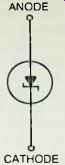
Fig. 8-1. Zener diode circuit symbol.
The breakdown point is rounded to some extent, this curvature being referred to as the "knee." The sharper the knee, the better the diode performs in most applications. In zener diodes of some types, the knee is so sharp that no curvature is visible unless the scale is expanded sufficiently to reveal it.
In most applications, the zener diode is DC biased to a point (such as zener voltage Vz and the corresponding zener current Iz in Fig. 8-2B) somewhere in the breakdown region.
The forward conduction characteristic is usually of no interest, so it is shown by a dotted line in Fig. 8-2(B). With the diode operating in the zener region, a large change in current produces a small (virtually zero) change in diode voltage drop. Conversely, a small change in voltage produces a large change in current.
In applications of the zener diode, the input (applied, or signal) voltage corresponds to the adjustable-voltage battery.
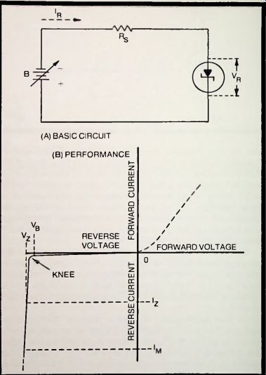
Fig. 8-2. Zener diode action.
B1 in Fig. 8-2(A). and the output voltage is chosen either as the voltage drop across the diode or the voltage drop across the resistor. For a given change in input voltage and therefore in diode current (IR ). the diode voltage drop is virtually constant because of the shape of the conduction characteristic (Fig. 8-2B). and the voltage drop across the resistor changes rapidly for the same reason. The constant diode voltage in the face of considerable input-voltage changes suits the zener circuit to constant-output applications, such as voltage regulation, peak clipping, and amplitude limiting.
SIMPLE DC VOLTAGE REGULATOR
The zener diode is best used for DC voltage regulation. This application exploits the virtually constant voltage drop across a zener diode operated in series with a current-limiting resistor. As the input voltage applied to the series combination fluctuates, the resulting current through the combination fluctuates proportionately, but the output voltage taken across the diode remains virtually unchanged.
Figure 8-3 shows the circuit of the simplest DC voltage regulator employing the zener method. With the 1N4020 diode shown here, the output of the circuit is 12 volts, up to 105 milliamperes. The series resistor, R1, is a 95-ohm, 2-watt unit; and because this is not a stock resistance, it must be made up by connecting a 75-ohm and a 20-ohm unit in series (individual zeners may require some adjustment of this resistance for best voltage regulation).
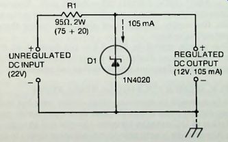
Fig. 8-3. Typical simple DC voltage regulator.
When the circuit is unloaded, the full current of 105 mA flows through the diode; but when the circuit is loaded, the current divides proportionately between diode and load, the total always being 105 mA. But as the load current fluctuates, the output voltage undergoes only a tiny change (see Fig. 8-2B). Similarly, when the input voltage fluctuates, the diode current correspondingly fluctuates; but large current fluctuations of this sort produce virtually no change in output (diode) voltage (again, see Fig. 8-2B). In this way, the simple circuit regulates output voltage against both input-voltage fluctuations and load fluctuations.
A simple arrangement such as that in Fig. 8-3 is often employed as a compact voltage regulator for the power supply in an electronic device. It is used also to stabilize the DC supply voltage at a single point in a circuit (as at the collector of a sensitive transistor). Occasionally, it is used in conjunction with a battery-type power supply to provide constant DC voltage as the battery ages. For an example of the convenience of the simple zener-diode regulator, see D1 in Fig. 3-8 ( Section 3).
The output voltage is determined by the zener-diode ratings, and so is the output current. The 1N4020 unit shown in Fig. 8-3 is a 12-volt. 105 mA diode. A wide variety of ratings may be found in the diode manufacturer's literature, so that a zener diode is available for every standard output voltage and many currents. For a particular diode and an available input voltage, the series resistance (RD must be calculated:
R1 = (E1- E0 )/I
where E1 is the available input voltage (volts), E_0 is the output voltage (diode voltage, volts), and I is the rated zener current (amperes).
Thus, for 18 volts output, a 1N3795A diode is available and is rated at 21 mA; and for this diode to be operated with a 25-volt supply, R1 = (25 - 18)/0.021 = 7/0.021 = 333 ohms.
The power dissipated by this resistance would be:
I^2R1 = 0.021^2/333 = 0.000441/333 = 0.0013 mW.
Because of the inherent voltage drop across the series resistor in the zener circuit, the supply voltage must always be higher than the desired output voltage.
The simple circuit in Fig. 8-3 is the basis of so many applications of zener diodes that it merits the time taken by a reader to become familiar with its design and operation.
SIMPLE, HIGHER VOLTAGE DC REGULATORS
It is common to associate zener diodes with low-voltage DC regulation, since it was the first device to provide simple regulation of DC voltages between 1.8 volts and 50 volts. And while it is entirely practicable to connect zener diodes in series for higher voltages (the regulated voltage being the total of the separate rated zener voltages) so long as the diode current
ratings are identical, there are available single zener diodes that will do the job by themselves. Thus, in some applications where current requirements are the same for both devices, a single higher voltage zener diode can replace a gaseous regulator tube such as OA3/VR75 (75 volts), OA2/VR150 (150 volts). OB2/VR105 (105 volts), or OB3/VR90 (90 volts).
Figure 8-4 shows six DC voltage regulators of the simple type, each employing a single zener diode. Except for the use of a higher voltage diode, each of these circuits is identical with the basic regulator circuit discussed in the preceding section, and that section should be studied for familiarity with the circuits. In each instance, the series resistor (R1) has been worked out for a typical input voltage; but since most of these resistances are not stock values, they must be obtained by series connecting lower values.
Electronic equipment of various types-including control devices, communications systems, test instruments, and data processing devices-can utilize simple DC voltage regulators of the zener type, such as are depicted by Fig. 8-4.
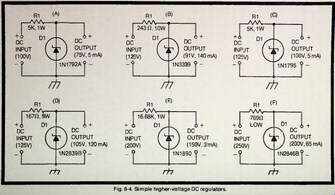
Fig. 8-4.
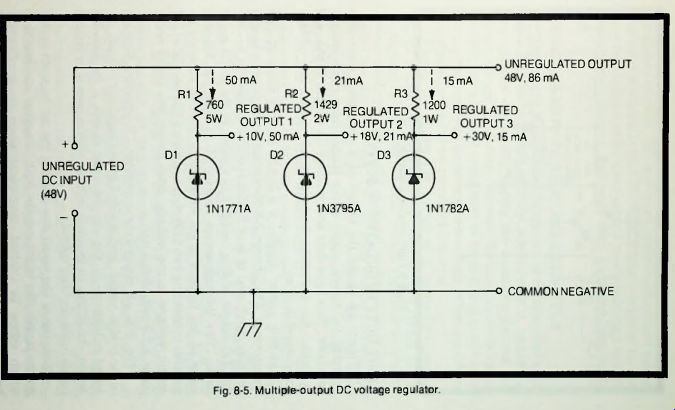
Fig. 8-5
MULTIPLE-OUTPUT DC VOLTAGE REGULATOR
It is often convenient to obtain several regulated output voltages from a single supply voltage. In the parallel circuit shown in Fig. 8-5. three such outputs (10, 18, and 30 volts) are obtained from a single 48-volt unregulated supply. While three outputs are shown in this arrangement, the same scheme may be used for as many more separate voltages as required, as long as the unregulated supply can provide the total required current. An examination of the circuit shows that each leg is a simple regulator of the type described previously.
In Fig. 8-5. the 1N1771A diode (D1) supplies 10 volts at 50 mA. the 1N3795A diode (D2) 18 volts at 21 mA. and the 1N1782A diode (D3) 30 volts at 15 mA. The series resistors (R1-R2-R3) have been worked out for the individual currents of these diodes; but since the first two of these resistances are not stock values, they must be obtained by series connecting lower values. All of the resistances may need some adjustment with individual diodes, for best voltage regulation. For a grounded-positive circuit, it is necessary only to invert the diodes and the input voltage; do not change the position of the series resistors.
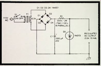
Fig. 8-6. Light-duty regulated DC supply.
LIGHT-DUTY REGULATED DC SUPPLY
Figure 8-6 shows the circuit of a complete, power-line- operated DC power supply with a simple zener-diode voltage regulator. This light-duty unit supplies 3.5 volts at 10 mA, and is useful for operating transistors and other low-voltage, low-current devices.
In this power supply, a 6.3-volt, 1.2-amp filament-type transformer, T1 (Stancor P-8190 or equivalent) drives a bridge rectifier composed of four 1N4001 rectifier diodes ( D1 to D4). The DC output of this rectifier is applied to the 1N373 zener diode (D5) through series resistor R1. (Since the 550-ohm value of this resistor is not standard, it must be obtained by parallel connecting two 1100-ohm resistors.) The regulated DC output voltage is the voltage drop across the 1N373 zener diode, a 3.5-volt. 10-mA unit.
The 2000 u-F electrolytic capacitor. C1, provides filtering of the bridge output, and is aided by the regulator circuit: An added advantage of the simple zener circuit is its filtering action. Its ability to regulate voltage also causes it to reduce ripple in the rectifier output.
Because of the small size of all of the components in this power supply, the latter may be built into other equipment in which space is limited. A typical place is a universal breadboard used for "dry wiring" circuits for transistors and integrated circuits. The unit is not limited to the output voltage and current shown in this example; higher voltage or current may be obtained in the same circuit by substituting a suitable transformer, resistor, and zener diode for those shown in Fig. 8-6.
5-VOLT, 1.25-AMPERE REGULATED DC SUPPLY
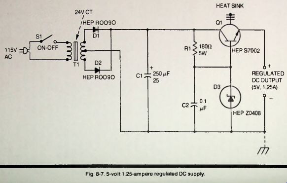
Figure 8-7
The simple zener-diode voltage regulators described in the preceding sections are entirely adequate in a number of applications where they supply the constancy desired. For closer voltage regulation, however, the more complex circuit (employing a control transistor) is needed, and in this latter circuit the zener diode serves as a voltage reference device.
Figures 8-7 and 8-8 show circuits of this type.
Figure 8-7 shows the circuit of a power-line-operated supply delivering 5 volts at 1.25 ampere. This circuit will be recognized as the conventional voltage regulator in which a power transistor (Q1) acts as an automatic series resistor to adjust the output voltage. The operating point of the transistor is established by the HEP Z0408 zener diode, D3. Because of the high collector current of the HEP S7002 transistor, a heat sink is required.
In this supply, power transformer T1 (Stancor P-6377 or equivalent) has a 24-volt center-tapped secondary, which drives the full-wave rectifier consisting of the HEP R0090 rectifier diodes. D1 and D2. The 250 uF electrolytic capacitor, C1. filters the DC output of the rectifier, and is aided in this function by the voltage regulator, which by its regulating action smoothes the ripple in the rectifier output. The 0.1 u-F capacitor (C2). in conjunction with the zener series resistor (RD provides still further filtering.
The HEP Z0408 zener diode is a 6.2-volt, 100-mA unit. The series resistor, R1, sets the diode current to 100 mA, and its 180 ohms is a stock value; however, this resistance value may need some adjustment with an individual diode.
This power supply circuit may easily be adapted for higher voltage or higher current service by appropriately changing the transformer, rectifiers, transistor, and zener diode. The zener voltage rating of the new diode must be equal to the desired new output voltage, and the new transistor must be able to pass the new current safely.
18-VOLT, 1-AMPERE REGULATED DC SUPPLY
Figure 8-8 shows the circuit of a conventional voltage-regulated power supply which is operated by an AC power line and delivers 18 volts at 1 ampere. This unit is similar to the one described in the preceding section, but employs a bridge rectifier (RECTI) instead of a full-wave, center-tapped rectifier.
In this arrangement, transformer T1 (Stancor P-6469 or equivalent) delivers 25.2 volts to the bridge rectifier which is rated at 50 PRV. The DC output of the rectifier is filtered by 2200 u-F electrolytic capacitor C1 and by the ripple-reducing action of the voltage regulator. Additional filtering action is provided by 0.01 uF capacitor C2.
The HEP S7000 power transistor (Q) serves as the automatic resistance element in the regulator, and the HEP Z2522 zener diode (D1) serves as the voltage reference. This diode applies a constant 4- 18-volt potential to the base of the transistor. For correct diode operation, the 330-ohm series resistor. R1. establishes a current of 21 mA in the diode. (R1 may need some resistance adjustment with an individual diode.) Because of the high current (1 ampere) flowing through the transistor and the external load. Q1 requires a heat sink.
This solid-state power supply is entirely conventional and demands no special techniques in its construction, except that adequate ventilation should be provided for the rectifier and transistor.
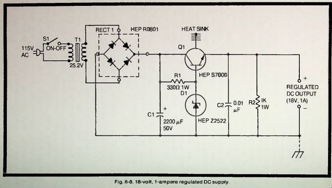
Figure 8-8
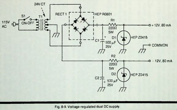
Figure 8-9
VOLTAGE-REGULATED DUAL DC SUPPLY
The power-line-operated supply shown in Fig. 8-9 provides separate +12-volt and -12-volt outputs, each at 80 mA. A unit of this type is useful for powering devices, such as integrated circuits, that require two identical positive and negative voltages. For regulation of the output voltages, two circuits of the simple zener type, each based upon a HEP Z0415 zener diode, are operated from the rectifier.
The rectifier itself (RECT 1) is of bridge construction (type HEP R0801), but is not used as a bridge. Instead, each half of the rectifier functions as a full-wave, center-tapped unit in conjunction with the center-tapped secondary of transformer T1. the right half delivering positive voltage, and the left half negative voltage. The power transformer has a 24-volt center-tapped secondary and is rated at 2 amps (Stancor P-6377 or equivalent).
In each regulator leg. current through the zener diode (D1-D2) is set by a 220-ohm series resistor (R1-R2). This resistance may need to be varied somewhat with individual diodes for the best voltage regulation. The diode current is 80 mA and is obtained when R1 and R2 are correct for D1 and D2, respectively.
Electrolytic capacitors C1 and C2 provide filtering action for the rectifier outputs. Additional filtering results from ripple reduction that naturally occurs in the voltage regulator action.
The small size of this power supply enables it to be built easily into other equipment, such as IC testers and universal breadboards for IC circuit development. The same basic circuit may be employed for higher voltage or current if suitable changes are made in transformer, rectifier, resistors, capacitors, and diodes.
REGULATED VOLTAGE DIVIDER
Figure 8-10 shows how zener diodes may be connected in series to produce a voltage divider that gives a regulated DC voltage at each tap. For this application, each of the diodes must have the same current rating, so that the current through the string will be a single value determined by series resistor R1.
In the divider shown here, regulated output voltages of 3.5 volts. 9.1 volts. 10.5 volts. 12.6 volts, and 23.1 volts are provided, all at 10 mA. Any other desired combination of voltages may be obtained by employing zener diodes rated at those voltages, insuring that each of the diodes has the same zener current rating, and employing a series resistance (R) that will limit the current in the string to that value for the available input (supply) voltage. Note that three of the voltages (3.5 volts. 12.6 volts, and 23.1 volts) are with respect to the common (negative or ground) terminal, whereas two of the voltages (9.1 volts and 10.5 volts) are above ground.
The divider in Fig. 8-10 operates from a 28-volt supply; hence, the series resistance (R1) required for 10 mA is 490 ohms. This is not a stock resistance value, and must be obtained by series connecting a 470-ohm and a 20-ohm resistor.
The resistance may need some adjustment with individual diodes, for best voltage regulation.
The regulated voltage divider is just as compact as one made up of resistors, since the diodes are of the same size as resistors. And it eliminates the troublesome voltage shifts that often occur when the loading of individual taps in a conventional divider is varied.
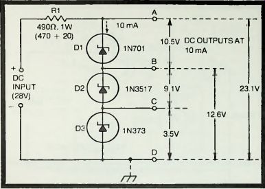
Fig. 8-10. Regulated voltage divider.
TRANSISTOR-BIAS REGULATOR
Stable operation of transistors demands that DC bias voltages be maintained constant. This is especially true of the base bias of a bipolar transistor. Figure 8-11 shows how a zener diode may be used in place of the lower resistor in a base-bias voltage divider to provide regulated DC voltage to the base of a transistor in an RC-coupled audio amplifier stage.
Here, the 1N370 diode, in conjunction with the 510-ohm series resistor (RD. supplies a constant -1.8-volt bias to the base of a 2N414 transistor. This voltage remains constant in the face of variations in supply voltage (B1) or transistor base current. Except for the substitution of the zener diode for the usual resistor, the circuit is the familiar common-emitter RC-coupled voltage amplifier.
In this arrangement, the 20 mA zener current for D1 is determined by the 510-ohm series resistor (R1) operated from the 12-volt DC supply (B1). For other bias values or supply voltages, select the zener diode that will supply that bias, and calculate the resistance needed to obtain the required zener current from the available supply voltage.
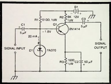
Fig. 8-11. Transistor-bias regulator.
VOLTAGE REGULATOR FOR TUBE HEATER
Vacuum tubes in sensitive locations-such as variable-frequency oscillators, electrometers, Q meters, and so on-often give improved performance if their heater (filament) voltage is held constant. Figure 8-12 shows how a zener diode voltage regulator may be used to stabilize the DC heater voltage of a type 8628 high-mu triode. The heater of this tube requires 6.3 volts at 0.1 ampere. The 1N1766 zener diode supplies 6.2 volts. The slightly reduced heater voltage often results in better operation of the circuit in which the tube is used.
In this arrangement, the 100 mA current of the diode is determined by the 58-ohm series resistor (R1) operated from a 12-volt supply. Since this is not a stock resistance, it must be obtained by series connecting a 36-ohm and a 22-ohm resistor.
Some slight adjustment of this resistance may be needed with an individual diode for best voltage regulation. For initial adjustment, temporarily disconnect the heater, and adjust R1 (if necessary) for a diode current of 100 mA. Then, reconnect the heater.
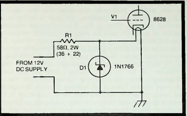
Fig. 8-12. Voltage regulator for tube heater.
SIMPLE AC VOLTAGE REGULATOR
Two zener diodes may be connected in series back-to-back to regulate the two half-cycles of an AC voltage. Figure 8-13 shows such an arrangement. Operating from 115 volts, this circuit delivers 105 volts at 120 milliamperes.
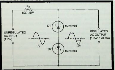
Fig. 8-13. Simple AC voltage regulator.
The AC voltage regulator is in effect two regulators, one for the positive half-cycle, the other for the negative half-cycle. When one is operating, the other is resting to all practical purposes. Thus, in Fig. 8-13 the positive regulator consists of diode D1. and the negative regulator consists of diode D2. Both diodes are served by the one series resistor, R1.
When D1 is limiting the positive peak, a 120 mA zener current flows through the two diodes in series; but D2 is conducting in the forward direction and accordingly offers very little resistance, so D1 is the "working" diode at this time.
Subsequently, when D2 is limiting the negative peak, the 120 mA zener current flows in the opposite direction through the two diodes in series; but this time D1 is conducting in the forward direction and offers very little resistance, so D2 is the “working" diode. This action limits both the positive and the negative peak to 105 volts, resulting in the clipped output waveform shown at (B).
For best results. D1 and D2 should be a matched pair. The common series resistor (RD is 82 ohms, a stock resistance, but this resistance may require some slight adjustment for best voltage regulation.
The 105-volt. 120 mA regulated output shown here is typical. Other values of voltage and current may be obtained from the 115-volt input and from other input voltages by suitably choosing zener diodes and the required R1 value. The 1N2839B zener diode shown here is a 12.6-watt unit.
AUTOMATIC VOLUME LIMITER
The basic AC voltage regulator circuit described in the preceding section may be employed to limit the amplitude of an audio signal. This application of the AC circuit is shown in Fig. 8-14; here, the maximum value the output voltage can have is 1.8 volts.
The circuit behaves in the same manner as the power-type AC voltage regulator. In this audio circuit, two 1N370 zener diodes are connected back-to-back in series, D1 conducting during the positive half-cycle and D2 during the negative half-cycle.
During the positive half-cycle, D2 behaves like a small resistance, this diode then being forward biased. Conversely, during the negative half-cycle, D1 behaves like a small resistance, this diode then being the forward-biased one.
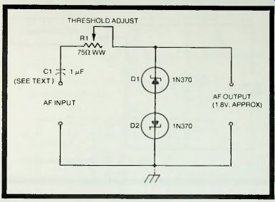
Fig. 8-14. Automatic volume limiter.
The threshold at which the output-signal clipping begins is adjustable to some extent by means of the 75-ohm wirewound rheostat. R1. If there is direct current in the output of the signal source that drives this limiter, the zener diodes must be protected from it by insertion of a 1 u-F nonpolarized capacitor, C1.
Because this is a clipper circuit, it introduces distortion in the output signal (see output waveform in Fig. 8-13). However, this distortion serves to indicate that excessive signal amplitude has occurred in the audio system and it can be corrected by needed reduction of gain, and the automatic action of the zener circuit protects the circuit and components from overdrive damage. The zener current of 20 mA is rather substantial in some audio systems, which means that the zener type of automatic limiter is most practicable in power systems. An advantage of the zener system over conventional diode clippers is its ability to operate without bias batteries.
DC-EQUIPMENT PROTECTOR
Because of its sharp breakdown and attendant heavy current drain, the zener diode may be used to clip a voltage transient or nullify a rise in supply voltage, thus protecting equipment from overvoltage damage. Figure 8-15 shows how an 18-volt zener diode may be connected simply in parallel with a 12-volt DC supply and the equipment (such as a receiver) that the latter powers. As long as the supply remains at 12 volts, the 1N3795A diode is in its nonconducting condition and appears as a very high resistance shunting the supply.
When, however, the voltage rises to 18 volts or when a transient of that voltage value appears. D1 conducts heavily and pulls the voltage down.
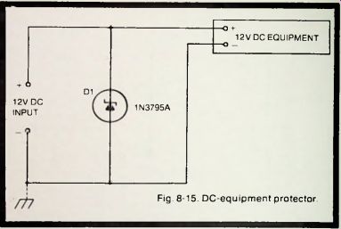
Fig. 8-15. DC-equipment protector.
The same arrangement may be employed for voltages higher or lower than 18 volts simply by selecting a zener diode having that voltage rating.
DC VOLTAGE STANDARD
The constant voltage drop across a biased zener diode may be used for calibration and standardization purposes. Figure 8-16 shows two circuits, each of which provides 1.8 volts. This voltage was chosen because it is close to the voltage of a common dry cell and of a Weston standard cell. A zener voltage standard may be powered by any convenient source--e.g., a battery, powered-line-operated supply, or generator.
Figure 8-16( A) shows a single-diode circuit. Employing a 1N370 diode, this circuit delivers 1.8 volts when it is powered by 3 volts input. The required series resistance (for 20 mA diode current) is the non-stock value of 60 ohms which may be obtained by series connecting two 30-ohm resistors.
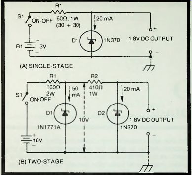
Fig. 8-16. DC voltage standard.
Greater constancy of output voltage, against input-voltage fluctuations, is obtained with a 2-stage circuit. The output stage then smooths out the fluctuations that normally are too low for the first stage to remove. Figure 8-16(B) shows such a cascade circuit. Here, the first stage, embodying a 1N1771A diode, delivers 10 volts from an 18-volt input. Any fluctuations in this 10-volt output then are removed by the second stage, which embodies a 1N370 diode. The output of this final diode is the required 1.8 volts. In this circuit, the first series resistance (R1) is a stock value; however, the second series resistance (R2) is a non-stock and may be obtained by parallel connecting two 820-ohm resistors.
DC voltage standards may be used for calibrating such devices as meters. DC oscilloscopes, potentiometric recorders, millivolt potentiometers, thermocouple systems, and similar apparatus.