| Home | Audio mag. | Stereo
Review mag. | High
Fidelity mag. |
AE/AA mag.
|
|
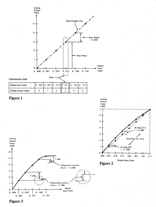
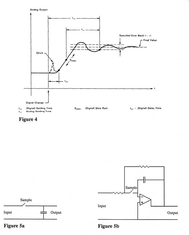
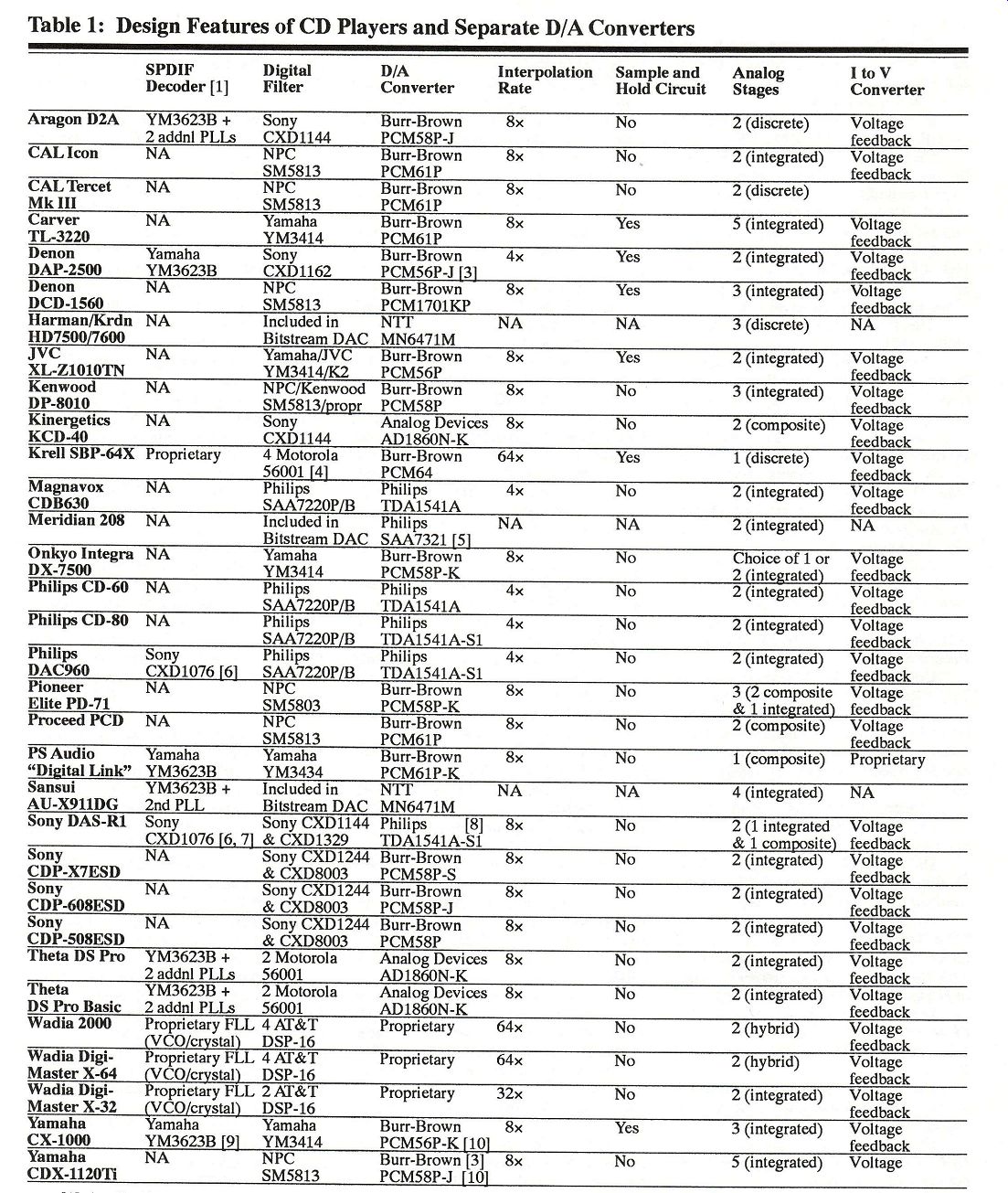
The Present State of CD Player Technology: Who Is Doing It Right? (Spring through Winter 1990-91) By David A. Rich, Ph.D. Senior VLSI Design Engineer, TLSI, Inc. Adjunct Assistant Professor, Polytechnic University This is an attempt to clarify at one fell swoop all the diffuse bits and pieces of information that keep cropping up in the audio press on the subject of CD playback and to put that whole technology in a critical engineering perspective. Editor's Note: Dr. David Rich is the new Contributing Editor on our masthead and a very serious classical music aficionado on top of his formidable electrical engineering credentials. His approach to audio is a little more technical than what our readers are accustomed to; for that reason some of his more esoteric digressions are broken out in sidebars to separate them from the main body of his article. You may want to pass over these on first reading and return to them later--but please, do return. Warning: The author will not--repeat, will not--take telephone calls from our readers at the company where he is employed or at the university where he teaches. You can reach him by mail, however, in care of this publication. Introduction This article explores the design of a modern CD player, offering insights into the design trade-offs of mid-priced and high-end players. Armed with this knowledge, you will be in a better position to distinguish differences between CD players. The best source of information about an electronic product is its service manual. Service manuals were consulted extensively in preparing this article. For small American companies that do not publish schematics or service manuals, marketing brochures and interviews with designers were the primary sources of in formation. Data is summarized in Table 1. We start with an analysis of the most important component of a CD player, the digital-to-analog converter. Digital-to-Analog Converters [Burr-Brown 1989], [Tex. Instr. 1989] The digital-to-analog converter (DAC) has the greatest effect on the sound of a CD player. The DAC accepts digitally coded data and produces an analog output in the form of currents and voltages (see Figure 1). Linearity is the principal performance specification for a DAC. Linearity is not a new concept in audio. In analog systems, it is the deviation from a linear transfer function, which gives rise to harmonic and intermodulation distortion [Borbely 1989]. The deviation from linearity in analog systems is usually well characterized. For example, bipolar devices have an exponential transfer characteristic. In analog amplifying devices, the distortion increases with increasing signal amplitude. (The crossover distortion in class B output stages is an exception.) The deviation from linearity of the amplifying device is reduced in almost all designs by global feedback. Care must be taken in applying feedback to prevent the formation of dynamic distortion products [Otala 1974]. A DAC's deviation from linearity differs from those characteristic of analog systems. The deviation, generally, is stochastic, randomly varying from one sample of the converter to the next. Systematic linearity errors occurring in each sample of a DAC are correctable by modifying the circuit design or layout of the chip. Distortion worsens as signal level decreases, and feedback cannot be used to linearize the DAC. One researcher has found that very small linearity errors in DACs can "produce audible modulation noise and extremely noticeable audio distortion" [Fielder 1989]. The step height of a DAC is the difference at the DAC's output between adjacent steps in the transfer curve of the DAC (see Figure 1). A perfectly linear DAC has steps of equal step height, as shown in Figure 1. Note that the step height has been normalized to 1 unit. This is the smallest analog step at the DAC''s output. An LSB step occurs when the Least Significant Bit (the last bit of an n-bit digital word) is changed while leaving other bits constant. The resolution of a DAC is the number of digits necessary to express the total number of steps. For example, a 16-bit DAC has 65,536 steps. There are many definitions of linearity error in a DAC. The most common to characterize the performance of a DAC are integral linearity (also called end point linearity or linearity) and differential linearity. Integral linearity is defined as the difference between the actual step value and the nominal step value, as shown in Figure 2. (The actual step values must be corrected for offset and gain errors where absolute DC voltage levels are required to be maintained. These errors are not important in audio applications.) The maximum linearity error is given in the DAC's data sheet. Linearity errors are often expressed as multiples or submultiples of 1 LSB. Differential linearity is defined as the difference between the actual step height and the ideal value of 1 LSB (see Figure 3). If a DAC has a differential linearity error of greater than 1 LSB, then the transfer function can be nonmonotonic, i.e, the output of the DAC can de crease even when the value of the digital code is increased. A resolution of 20 bits for a DAC is feasible, though the accuracy of the DAC is a function of the linearity errors, and the DAC may be accurate to only some smaller number of bits. If the 16-bit DAC has a maximum differential and integral linearity error of +2 LSB, it is no more accurate than a 15-bit DAC with a maximum differential and integral linearity error of +1 LSB. In other words, the accuracy of a DAC, not its resolution (the figure quoted by the marketing departments of CD player manufacturers), determines how linearly the signal will be reproduced.
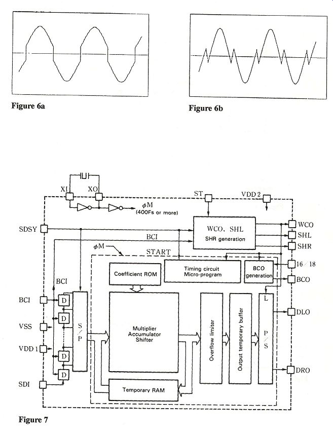
Figure 4 shows the dynamic response of a DAC to a step change in the digital input code. The glitch is a short, undesirable transient in the analog output following a code change at the digital in put. The glitch area, the time integral of the analog value of the glitch transient, should be as small as possible in DACs used in audio applications that do not in corporate a deglitching circuit. The settling time of a DAC (t_sd in Figure 4) is the total time required for the analog output to settle within an error band around its final value after a change in the digital input. The error band is usually +1 LSB wide. However, settling characteristics to wider error bands are important if the DAC is to function without a sample and-hold circuit. The value of settling time varies with the magnitude of the change in the digital word value. The conversion period is the time between successive digital codes being applied to the DAC. The conversion period should equal or exceed the settling time. The number of words presented to the DAC in one second is called the word rate. The word rate is a reciprocal of the con version period. The Best DACs Only the Burr-Brown DAC729KH digital-to-analog converter has a guaranteed 16-bit differential linearity error of one bit (it can be externally adjusted to 1/4 LSB) and an integral linearity error of 1/2 LSB for 16-bit resolution. The DAC729 can also settle within 1/2 of a 16-bit LSB when it is sampled at a 4x interpolation rate. Unfortunately, the DAC 729, which is not designed for consumer audio, sells for $197 (in quantities of 100). It is not a single monolithic chip. Rather, it is a hybrid circuit incorporating numerous state-of-the-art custom designed chips. The price of the DAC729, a product of hybrid technology, is 10 times greater than the maximum price a DAC in a high-end CD player would cost. The $12,000 Stax DAC-X1t digital to-analog processor uses a similar hybrid circuit, the DAC D20400 manufactured by UltraAnalog. The UltraAnalog circuit guarantees 18-bit differential linearity, but no specifications are supplied for integral linearity or settling time to a 16-bit LSB. The differential linearity specification holds only at room temperature. The Stax unit uses tubes in its output stage; thus the DACs may not perform to specs because of elevated operating temperatures. The distortion specifications of the Stax unit show that the very low distortion at the output of the UltraAnalog DAC is compromised by the tube output circuit's nonlinearities. [Ha-ha!-Ed.] Although typical specifications for differential and integral linearity are given for a consumer DAC, these ratings are not guaranteed. Instead, a set of THD values is specified. In this test, a sequence of digital words which represent sine waves of different amplitudes is transmitted to the DAC, and THD at the output is measured. Quoting from [Burr Brown 1989], "THD is the measurement of the magnitude and distribution of linearity error, differential linearity error, noise and quantization error. Distortion, attributable to quantization error, can be eliminated if a dither is added to the sine wave {Lipshitz and Vanderkooy 1988}.] There is a correlation between the THD and the square root of the sum of the squares of the linearity errors at each dig ital word of interest. However, this does not mean that the worst-case linearity error of the D/A is directly correlated to the THD." The DAC with the lowest guaranteed THD levels is the UltraAnalog DAC D20400 hybrid. Since the THD of a DAC can be difficult to measure be cause of the low absolute value of the distortion products, an alternate, simpler test is often used to assess DAC linearity. This test is called gain linearity. Gain linearity is the measurement of the deviation of the amplitude of the sine wave's fundamental component from the ideal value, for sine wave signals of varying amplitude ranging from full scale to be low an LSB. This is commonly called the linearity test, and the errors are reported in LSBs. This test, widely used by audio magazine reviewers, should not be con fused with the more stringent integral and differential linearity tests. Philips re searchers have developed a test signal which explores differential linearity over a wide dynamic range [Dijkmans and Naus 1989]. The test uses a 400 Hz sine wave recorded at -80 dB in combination with a .03 Hz sine wave at -20dB. This test will expose differential linearity errors that are not found using single-tone THD measurements. If a DAC does not have a low glitch energy, or if it does not settle within a small percentage of the sampling period, it must be followed by a sample-and hold circuit. The sample-and-hold samples an analog input signal value and then holds the instantaneous input value upon the command of a digital control signal. Figure 5a is an idealized sample and-hold circuit. In the sample mode, the switch opens and the capacitor stores the value of the input voltage at the point the switch opens. The circuit samples the output of the DAC after the converter has nearly settled to its final value. This val ue is then held on the capacitor when the next data word is presented to the DAC. Figure 5b shows a simplified circuit dia gram of a sample-and-hold. In the sample mode, the circuit acts as a unity-gain inverting amplifier. In the hold mode, the capacitor holds the value of the output at the time the switch is opened. As will be discussed, the implementation of this particular circuit has its problems. Ulti mately, it is not possible to build a cost-effective sample-and-hold that does not distort the input signal. All of the current DACs designed for use in high-end CD players operate without a sample-and-hold circuit. These include the Philips TDA1541A (16-bit resolution), the Burr-Brown PCMS56P (16-bit resolution), the Burr-Brown PCM58P and PCM61P (18-bit resolution), the Analog Devices AD1856 (16 bit resolution) and AD1860 (18-bit resolution). The PCM56P was revised so it can be used without a sample-and-hold. Older CD players that used this chip had a sample-and-hold circuit. (The high priced Burr-Brown DAC729KH, unfortunately, does require a sample-and-hold circuit. The UltraAnalog DAC D20400 includes a sample-and-hold as part of the hybrid circuit. The differential linearity and THD specs for the D20400 include the sample-and-hold circuit.) The precursor to the PCMS58P, the PCM64P, was the first 18-bit resolution DAC. It required a sample-and-hold circuit for proper operation. I compared the sound of the Pioneer PD-91 and Sony CDP 707ESD, which used the PCM64, to that of their respective successors, the Pioneer PD-71 and Sony CDP-X7ESD. The latter are similar but not identical to the older models, with the principal difference that they incorporate the PCM58P. Although my listening comparison was not double-blind or even single-blind, ...
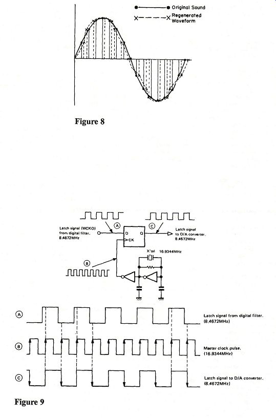
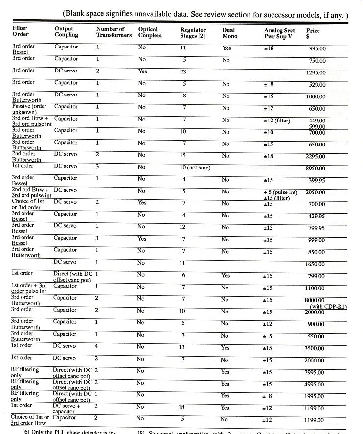
---- Figure 6a Figure 6b, Figure 7 ... nor at exactly matched levels, my impression was that the sound of the new units is significantly more open and less "electronic." I attribute this difference to the elimination of the sample-and-hold stage. One potential problem in removing the sample-and-hold circuit is the feed through of digital clock signals to the analog output of the converter. Digital signals typically have a peak-to-peak amplitude of 5 V. These signals enter the DAC to encode the next digital word into the DAC and they determine when the conversion process begins. Normally, these signals would not be running during the period that the output of the DAC is sampled. When the DAC's output is continuously connected to the input of the analog circuit, a change in a digital signal's value may slightly affect the analog output. This is probably a third order effect, though some designers of high-end CD players minimize it by con trolling the rate of rise and fall of the dig ital signals connected to the DAC. They also align the transition time of all the digital signals that enter the DAC. Denon, JVC, Technics, and Yamaha add external circuitry to increase the resolution of digital-to-analog conversion two bits beyond the resolution of the DACs they are using. High glitch energy is one problem with these systems. Consequently, a sample-and-hold circuit is required. The Yamaha CDX-1120 eliminates the sample-and-hold with a new low-glitch implementation of their floating-bit DAC. In addition, the problem of matching the components added to the DACs in these systems tends to limit the accuracy of these CD players. These systems, I believe, are incapable of matching the accuracy of the best available monolithic DACs. I would greatly hesitate to purchase a CD player with external circuitry for the purpose of enhancing DAC resolution. Denon (in the DAP-2500 digital audio preamplifier), Kinergetics (in the KCD-40), and Yamaha (in the CDX 1120) use a novel approach for reducing the nonlinearity of a DAC, in which a pair of DACs are wired in a push-pull configuration. One DAC in the pair receives digital information which has been modified so that the polarity of the signal entering the DAC will be inverted. The analog current-to-voltage converter takes the difference between the respective current outputs of the two DACs. Matched even-order nonlinearities that appear at the output of the two DACs are then cancelled. This approach is success fully adopted in analog circuits characterized by closely matched even-order nonlinearities. Most DAC nonlinearities, however, are caused by random processes, and they do not match between dies. Thus, only the small systematic nonlinearities will be canceled. This approach is very expensive because each channel is serviced by a pair of DACs. A single, highly linear DAC will outperform two less linear DACs wired in a push-pull configuration. Hence, the push-pull topology should be used only with the highest-grade DACs available. It is not possible to fabricate the internal circuit components in a DAC to match closely enough to achieve 16-bit accuracy. Burr-Brown and Analog De vices adopt a technique called laser trimming. A laser adjusts the value of the critical resistors on the chip during the initial testing of the silicon wafer. After this test, the wafer is split into individual chips, which are then placed in plastic packages. The packaging of a die can effect its performance through exposure to mechanical stress. Final packaged parts are retested. Not all of these parts perform equally. Devices with the best THD performance are separated. These DACs are then sold at different price points, de pending on their respective THD performances. DACs are generally classified into one of three grades. Suffixes are attached to the part number to indicate its quality. Ranking the DACs A current ranking of DAC accuracy, in ascending order of improved performance, is as follows. Category 1: AD1856 AD1860 PCM56P PCM61P Category 2: AD1856-j AD1860-J PCMS56P-j PCM61P-j Category 3: PCMS58P Category 4: AD1856-K AD1860-K PCM56P-K Category 5: PCMS58P-J Category 6: PCM61P-K Category 7: PCM58P-K The PCMS8P and PCM61P are guaranteed to meet their distortion performance specifications without a de-glitcher. In my opinion, only the DACs in the last four categories should be used in a mid-priced or high-end CD player. The PCM56P-K and AD1856-K, albeit 16-bit DACs, offer better linearity than some of the 18-bit resolution devices. These 16-bit DACs are cheaper than the less accurate 18-bit models, though marketing considerations curtail their use. One of the leading DAC designers calls the extra two bits "marketing bits." For a CD player with a four-figure price tag, I would consider only a PCM58P-K or a PCM61P-K. Engineers at Madrigal, The ta, and CAL have selected the PCM61P K device for their machine, claiming that it offers better sonic performance. Theta has performed measurements which they claim show the PCM61P-K to be more linear than the PCMS58P-K; however, they are now using the AD1860-K. Some manufacturers use lower selection grades of DACs, asserting that the selection pro cess is done in-house. This is hardly convincing, since the binning process ensures that the lowest-grade DACs will have the poorest performance; all DACs with superior performance have already been removed. (An exception to this rule occurs if the number of top-grade DACs produced exceeds the demand for them. When this happens, some of the top grade DACs are marked with a lower grade). The Burr-Brown PCM1700P and Analog Devices AD1864 contain two DACs on one silicon chip. This allows the use of a single chip for stereo applications. The Analog Devices part comes in blank and J grades, and its performance is identical to that of other Analog Devices parts of the same grade. The PCM1700P yields performance that is slightly poorer relative to the PCM58P for a given part grade. (The comparisons are complicated by the fact that the THD levels of the PCM58P are specified at a different sampling rate than those of the PCM1700P.) The architecture of a practical DAC causes the worst differential linearity error to occur at the most significant bit (MSB). The MSB is the largest incremental output change obtained by switching a single input bit. This is un fortunate because the MSB change occurs when the output of the DAC passes through zero. For small-amplitude sine waves, the differential linearity of the MSB can have a significant effect on signal distortion. Figure 6a shows a sine wave when it is reproduced by a DAC with large positive differential linearity error at the MSB. Figure 6b shows a DAC with a large negative linearity error. The DAC of Figure 6b is not mono tonic. To reduce distortion, the Analog Devices and Burr-Brown DACs allow an external trim adjustment that trims the differential linearity error at the MSB change close to zero. The PCM58P al lows adjustment of bits two through four in addition to the MSB. Designers debate whether these adjustments offer addition al sonic performance improvements. The accurate adjustment of these potentiometers is difficult in a production environment, and independent laboratory tests confirm that many units are shipped with the adjustments incorrectly performed [Lipshitz and Vanderkooy 1988]. [See also the CD playback equipment reviews in this issue. -Ed.] The Philips TDA1541 uses a different architecture than the Burr-Brown and the Analog Devices DACs. The architecture applies a proprietary technique called Dynamic Element Matching. The architecture allows the DAC to achieve 16-bit linearity without laser trimming or external adjustments. The elimination of an external adjustment is especially advantageous since a trim pot can change with age. The top-of-the-line TDA1541A S1 offers first-class performance, but it is not possible to rank this DAC with the American DACs above because the guar anteed specifications for the American DACs and the Philips are different. (The American manufacturers guarantee distortion and Philips guarantees differential nonlinearity.) In the CD players tested for review in this issue, the best DACs from Burr-Brown were found to have lower distortion at -90 dB than the Phil ips TDA1541A S1. Until the new American DACs that did not require a sample and-hold circuit made their appearance, the TDA1541A S1 was used almost exclusively in all high-end CD players. Manufacturers such as Sony, CAL, and Kinergetics have now chosen alternative chips from Burr-Brown and Analog De vices. Moreover, newer companies entering the field (e.g., Krell, PS Audio, Aragon, and Proceed) use the Burr-Brown devices. Philips remains the preference of European companies. Burr-Brown and Analog Devices are continuing the development of audio DACs. For this reason, you should make sure that any very expensive CD player or decoder you are contemplating to purchase can be upgraded to the newer DACs when they become available. The most recent DACs from Burr-Brown and Analog Devices are the PCM63P and AD1862 respectively. The PCM63P uses a new topology which steps away from zero in small steps in both directions to reduce low-level nonlinearity. The AD1862 uses a digital offset technique which shifts the zero level away from the MSB transition. The PCM63P-K and AD1862N-J chips have better linearity performance than the PCM58P-K. The PCM63P-K data sheet lists slightly better THD specifications at the 20 dB and -60 dB levels in comparison with the ADI1862N-J. (Again, the comparisons are complicated by the fact that the THD levels of the PCM63P are specified at a different sampling rate than those of the AD1862. In addition, the THD for the AD1862N-J is an A-weighted measurement.) The lower grades of these DACs are not as linear as the PCM58P-K. The THD level of the UltraAnalog DAC 20400 hybrid is 6 dB lower than that of the PCM63P-K at -90 dB. The resolution of the new DACs is 20 bits. (The higher resolution also satisfies the marketing department.) It takes approximately 6 to 12 months after the introduction of a component before it begins to appear in a commercial product. Pioneer is the first company to announce the use of the PCMG63P. The new Pioneer CD players are the PD-73 and PD-93. These units are expected to become available by the time this article is in print. [That's sufficient lead time. -ed.] Digital Filters and Interpolators [Lipshitz and Vanderkooy 1988] All quality CD players now place a digital filter and interpolator (the term oversampling should be reserved for an A/D converter sampling at a rate much faster than the Nyquist rate) ahead of the DAC. A digital filter affords significant reductions in the complexity of the analog filter. With a 4x interpolation rate, the analog stage could be formed with only two active gain stages. With an 8x interpolation rate, a single active gain stage can be used. A well-designed digital filter should introduce virtually no signal distortion. This is in contrast to a high-order analog filter, an analog circuit which, owing to unavoidable nonlinearities in the active devices, can introduce significant distortion and frequency response variations. An engineering trade-off must be made between the reduction in the complexity of the analog stage and the increase in nonlinearities at the DAC output. This is because the linearity of the DAC can be degraded when the conversion period of the DAC is reduced. A DAC operated at an 8x interpolation rate will have half the conversion period of one operated at a 4x rate. Digital filters often use a set of cascaded, finite impulse response (FIR) filters. The sampling rate of each filter section is increased relative to the section which precedes it by a power of 2. The bulk of the filtering takes place in the first section, since this section operates at the slowest clock rate and is therefore easier to design. Finite impulse response filters, which are difficult to design in the continuous time (analog) domain, have the significant advantage of being linear phase if the coefficients are chosen properly. Because of the linear phase characteristic, such a filter exhibits better time domain response to a pulse than an analog filter. The smoothness of the passband, the slope of the transition band, and the attenuation of the stopband are determined by the size of the FIR filter. The size is measured by the number of delay blocks in the filter and is called the tap length of the FIR filter. (There are N+1 taps in a filter with N delay blocks.) The comparison of the tap sizes of different digital filters is valid only if the filters have the same interpolation rate. A properly designed filter's passband flatness is, remarkably, less than 0.0001 dB. This is insignificant compared with the frequency response errors in the analog chain. A designer of CD players who wishes either to improve upon off-the-shelf filter chip designs or to incorporate additional ideas of his/her own will need plenty of money. A design team of engineers would require at least a year, owing to the chip's complexity, to develop and fabricate such a chip, which may need upwards of 100,000 transistors. The cost of engineering time and materials would be in the $200,000 to $500,000 range. This investment is well out of the reach of small American audio companies. Because a custom chip, fabricated for a single company, would be used in much smaller quantities than a standard product, the cost per chip would be much higher than that of off-the-shelf digital filter chips. The only solution for a small American audio company designing a state-of the-art product is to design with a general purpose DSP chip, external RAM, ROM, and a number of smaller glue chips. The glue chips, as the name implies, form the interfaces between the other chips in the system. Because of the large computational requirements, more than one DSP chip may be required (one for each channel, for example). The cost of this group of chips is much larger than that of a single monolithic device. The Motorola DSP56000 is proving to be the most effective chip for this application. The high prices of the Theta ($2000 to$4500), the Krell ($3500 to $8950), and the Wadia ($1995 to $7995) reflect the cost of implementing the digital filter with general-purpose DSP chips. Some of these units run at much higher interpolation rates (16x to 64x) than the monolithic filters. The manufacturers of these units claim that the monolithic chips do not perform the interpolation function accurately. In the monolithic chips, an ideal brick-wall filter, which is required by the sampling theorem for the exact reconstruction of the input data, is approximated by the FIR filter. A brick-wall filter has a sin x/x impulse response. The time domain form of the sampling theorem states that when a sin x/x function is convolved with samples of a bandlimited input signal, the bandlimited input signal will be reconstructed exactly [Papoulis 1980]. The impulse response of the FIR filter is finite and of the sin x/x function is infinite. The coefficients in the filter are slightly modified to account for this --------------- Inside the Digital Filter The topology in which a digital filter is implemented is a highly specialized microcontroller called a digital signal processor (DSP). A block diagram of a digital filter, the Yamaha YM3434, is shown in Figure 7. The circuit blocks which constitute the DSP "engine" are all inside the smaller dashed rectangle. Other blocks within this rectangle (BCO generation, P/S, output temporary buffer) and those outside it are specialized digital circuits for format ting data from the CD player's disc-reading circuitry. These circuits also make the data available to the filter's DSP engine and send the output of the latter to the DAC. As for the DSP engine itself, it functions as follows: The coefficient ROM stores the digital words which control the filter's shape. The multiplier/accumulator performs the arithmetic operations required for the filter. The accumulator stores partial and complete computations from the multi plier. The shifter manipulates the digital words during the multiplication process. The temporary RAM block is required to store the output of the accumulator because the processing of the cascaded filter blocks is performed in parallel, and the data emerging from the accumulator is not the data for the next computation. The ROM, RAM, and the arithmetic unit are con trolled by the timing circuit block. The microprogram, which is stored on a ROM internal to the timing circuits, controls the operation of the filter. The word length of the coefficient ROM partially determines the accuracy of the filter response. The effect on passband response is not important, e.g., the NPC SM580S, which has a short 16-bit word, is flat +0.00025 dB. The added word size has a more important effect on the stopband rejection. The Sony CXD1144BP, which has 293 taps and a 22-bit coefficient word length, has a stopband rejection exceeding 120 dB. When two digital words are multi plied, the resultant word length at the output of the multiplier is the sum of the input word lengths. This word is too large to use and must be shortened (requantized). The process of shortening introduces quantization distortion [Dijkmans 1989]. Some digital filters truncate the word. This is a less desirable process than a rounding operation. Lipshitz observes that, in addition to rounding, a dither signal must be added during the multiplication process to ensure that all quantization artifacts are removed. No current monolithic DSP chips use dither. (Dither has been used in certain Theta and Wadia digital decoders, but given the constantly changing filter algorithms used by these companies, it is unclear if dither is used in current production models.) Note that adding dither at the input of the DAC has no advantage, provided analog dither was added during the recording process. Adding dither is standard practice in modern recordings [Lipshitz and Vanderkooy 1988]. The bus of data connected from the arithmetic unit and the temporary memory is called the data path. The word length of this path is another parameter which affects the filter's performance. The data path word length is usually the word length of the DAC, though it may be larger if noise shaping is performed. The marketing departments have recently taken notice of the word length of the coefficients, accumulator output, and data path. They are using these in advertising copy, perhaps with hopes that readers will confuse these larger numbers with the resolution of the DAC. The optional noise shaper can round the data at the accumulator. Normally, the noise power is constant from DC to half the sampling frequency. A noise shaping filter is an IIR filter, a filter with an infinite impulse response, which redistributes the quantization noise shape. A noise shaper reduces the noise power in the audio band and increases it outside the audio band. The signal-to-noise ratio of the signal bandlimited in the audio band increases. Noise shapers exhibit low-level instabilities called limit cycle oscillations. Proper rounding operations and use of dither prevent this, as apparently does dither added in the recording process. Noise shaping is used on two 18-bit digital filter chips, the NPC SM5803 and Sony CXD1244. The noise shaping can be turned on and off under software control. Therefore, a service manual may not show whether a given CD player is using noise shaping. Interpolating digital filters are also plagued with potential overload. This overload arises because signal amplitude at the output of the filter can be greater than that allowed by the word length of the filter. The amplitude increases because of the Gibbs phenomenon [McGillen and Cooper 1974], which occurs when a signal is band limited and all its Fourier coefficients are not present. An example of the Gibbs phenomenon is seen in test reports on CD players as an oscillation on the top and bottom portions of a square wave. The problem is worsened by an increased filter interpolation rate. Lipshitz calculates that two bits of headroom are required in a 4x interpolating filter. Attenuation of the input signal to the digital filter will solve the problem, but attenuating the input penalizes the signal-to-quantization-noise ratio of the filter beyond acceptable levels. Hence, most monolithic filters detect the presence of an overload and allow the filter to clip. It is unlikely that the filter will clip in the presence of music signals as distinct from test tones. The extra bits available from an 18-bit DAC could provide the headroom, though this is not done on current monolithic filters. The designers of these filters prefer to use the extra bits to reduce the quantization noise introduced in the truncation process at the output of the accumulator. Currently, there are only four manufacturers of monolithic digital filter chips: NPC, Sony, Yamaha, and Philips. The prices of the chips are dependent on the complexity of the DSP section. A filter with more taps, longer coefficient ROM words, longer data path, or a larger accumulator will be costlier. The Sony CXD1144 18 by 8 filter is the most complex chip to date, and it is priced at double the competing NPC SM5813 (the similar SM5803 adds a noise shaper and other features that do not impact on the performance of the DSP core) and Yamaha YM3414. Sony's newest design, the CXD1244, has not as yet been adopted by any manufacturer other than Sony. The performance of each of the 8x interpolating filters is summarized in Table 3. Sony has not quoted the multiplier size, coefficient word length, or filter tap length in its data sheet of the new CXD1244. The ripple rejection of the CXD1244 and its stopband rejection are slightly inferior to those of the CXD1144, indicating a simplified design relative to the CXD1144. The lower cost of the CXD1244 also supports this notion. The CXD1144 is often cited by circuit de signers as the best-sounding single-chip digital filter. It should be noted that none of the differences in passband or stopband characteristics given in Table 3 should be audible. Therefore, it is unclear how the increased complexity of the CXD1144 results in better sonic performance. Most Philips TDA1541A's are used in tandem with the Philips SAA7220P/B digital filter, although some Sony digital filters have functional modes which make them compatible with the TDA1541A at a 4x interpolation rate. The CXD1244 chip allows the reproduction of very small signals without switching the MSB bit because it can apply a small DC offset to the digital code emerging from the filter. This feature is unique to the CXD1244. Very small signals are reproduced with lower levels of distortion. The DC offset would cause the positive peak of large-amplitude signals to exceed the maximum digital word size of the filter, thereby clipping the positive peak of the signal. To avoid this, all signals entering the digital filter are slightly attenuated in amplitude. The Philips digital filters have a very similar feature but differ from the Sony CXD1244 inasmuch as the DC offset cannot be defeated. ----------------------------
------ Figure 8; Figure 9 
----- Figure 10; Figure 11 [...] [Papoulis 1980]. Coefficient modification routines are well-known and give good results. Wadia, Krell, and Theta claim that the method used by the monolithic chip manufacturers is less than ideal. In the case of the Theta, the coefficients are also adapted, depending on signal conditions. The Wadia and the Krell perform the interpolation function directly in the time domain rather than the frequency domain. As none of these companies have published their current algorithms in the open literature, it is impossible to assess their methods. Wadia has published information on an earlier time-domain algorithm using Lagrangian interpolation [Moses 1987]. The performance criterion for a digital filter that performs interpolation and smoothing is the Mean Square Estimation Error (MSEE) [Papoulis 1984]. None of the manufacturers have published any data showing that their filters have a lower MSEE than a low-cost monolithic filter. [Touché!- Ed.] Time-domain interpolation algorithms have the major disadvantage of not rejecting the out-of-band spurious signals with as great attenuation as a FIR filter [Cezanne 1988]. Martin Colloms has found this problem in his measurements of the Wadia 1000 and the Krell units [Colloms 1989], [Colloms 1990]. The Wadia sales literature points out that the digital impulse response of the Wadia system rings less than a standard digital brick-wall filter. The amount of ringing in the impulse response is directly related by the Fourier transform to the stopband rejection of the filter. The lack of ringing in the tails of the digital impulse response curve for the Wadia system is a direct result of the poor stopband rejection. The sampling theorem requires that the signal at the input of an analog-to digital converter must be bandlimited to one half the sampling frequency. An analog or digital brick-wall filter must be included in the digital tape recorder to satisfy the sampling theorem. Thus, the impulse response of a complete digital audio system (analog in to analog out) will be that of a brick-wall filter regard less of the response of the playback system to a digitally generated unit impulse. [Touché again.-Ed.] Martin Colloms also found that the frequency response of the Wadia 1000 and the Krell units was down by 3dB at 20 kHz. This indicates that the Wadia and Krell algorithms have not been optimized for maximum pass band flatness. In a recent piece of promotional literature, Wadia implies that the results of the sampling theorem cannot be applied to music signals. They argue that in the derivation of the sampling theorem the Fourier series is used. They claim the Fourier series cannot be used to represent the stochastic music signals. This statement is completely false. It has been shown that the sampling theorem is equally valid for bandlimited random signals [Papoulis 1984]. One hopes that the Wadia copywriters misunderstood the Wadia engineers. Wadia has implemented the glue circuitry in a programmable gate array manufactured by Xilinx. The interconnection of the circuitry is controlled by software programmed into a programmable ROM (PROM). The circuitry for the SPDIF de coder (see below) is also implemented in the programmable gate array. Wadia can thus correct errors or upgrade the circuit configuration of the decoder box by changing the code in the PROM. Phase Jitter and SPDIF A sampled data system's performance is critically dependent on the accuracy of the sampling time interval. Variation in the absolute timing of successive spacings is called phase jitter (or Jitter). A sampled sine wave signal corrupted with phase jitter will, when examined on a spectrum analyzer, appear as a narrow Gaussian-shaped band of signals. The resulting signal spectrum is very similar to that of an analog signal reproduced from a turntable or tape deck with flutter. The effect of jitter on the time domain plot of a sine wave is shown in Figure 8. The crystal oscillator which generates the clock signal is generally jitter-free. Time-base jitter can arise if the power supply signals to the crystal oscillator become noisy. Kenwood proposes that clock noise induced by the CD tracking system gives rise to time-base jitter. According to Kenwood, this explains the claim that CD rings and disc stabilizers change the sound of a CD. The obvious solution is to ensure that the supply to the crystal oscillator is well-regulated. A problem is that the crystal oscillator circuit is often incorporated in the digital filter IC. Noise on internal chip power supply lines cannot be removed. The solution to this problem is to build the crystal oscillator as a separate circuit and drive the digital filter with the output of this circuit. This approach is used by Stax, Sony, and CAL, among others. Another source of time base jitter occurs when the crystal oscillator signal is divided down to the word rate of the DAC in the digital filter chip. The source of the jitter is again power supply noise. Resyncing (realigning) the edges of the clock waveform at the output of the digital filter with the master clock will reduce this timing jitter mechanism. Sony, in its CDP-508/608/X7ESD players, performs the resyncing with a custom IC, the CXD8003. Kenwood uses a similar chip called DPAC (Digital Pulse Axis Control) in its DP-8010 player. The basic DPAC circuit is shown in Figure 9. The system in Figure 9 al lows the latch signal to the DAC to change only on the rising edge of the master clock. The practical implementation of the DPAC circuit is significantly more complex than the circuit shown in Figure 9. JVC has found [JVC 1989] that additional sources of jitter include noise
coupled into the clock line from adjacent signal lines by mutual inductance
and mutual capacitance. In addition, signal reflections in the interconnection
lines between ICs can cause jitter. The K2 interface is a functional block
developed by JVC to suppress jitter. The K2 Inter face combines optocouplers
and a data resyncing circuit. The K2 Interface is placed before the digital
filter; some jitter may be reintroduced by the filter IC. I think these
manufacturers may be attacking a second-order problem while leaving other
major design flaws in their players unresolved. For example, the Sony CDP-508ESD
uses an unselected Burr-Brown PCM58P DAC. It would have been preferable to
eliminate the CXD8003 from the 508 and channel the cost savings towards an
upgraded DAC. This is the data format used in connecting a CD player to an external digital de coder box [Rumsey 1989]. The SPDIF uses a single cable to transmit data recovered from the CD player. The data is specially encoded so that the clock signal can be recovered from the data. (See sidebar for technical details.) Some subjective reviewers have cited differences in the sound of the output of a decoder box when driven with different transports. If the differences are real-and that remains to be proved with properly conducted ABX tests--then jitter is the culprit. Some high-end manufacturers propose expensive transports with low jitter. This is of little conse quence, since the jitter problem can only be completely eliminated in the decoder box. Wadia and Theta claim that the bandwidth of the optical cable system used for the SPDIF format is inadequate. This can give rise to jitter. Coaxial cable designed to transmit wide-bandwidth digital signals is recommended instead. Unlike audio cables, these coaxial cables will transmit the SPDIF signals
precisely. An example of such coaxial cable is RG 59, which sells for 20 cents per foot. You can bet that the snake-oil manufacturers will be introducing SPDIF interconnects at $100 apiece. One final observation. I found the PS Audio "Digital Link," which uses only the Yamaha YM3623B chip, to have an excellent sound quality when used with a high-quality transport such as the one in the Philips CD-80 or the Pioneer PD-71. This indicates that the jitter level of the YM3623B is sufficiently low so that it does not significantly affect the sound quality of modern decoder boxes that use it. The early Philips and Sony decoder boxes had less sophisticated SPDIF decoders and may have more jit ter. The Yamaha CX-1000U preamplifier/ decoder incorporates several clever cir cuits placed around their YM3623B chip to reduce jitter even further. Yamaha is trying to keep these circuits for themselves. They are not discussed in the YM3623B chip data sheet. New SPDIF decoder chips are currently being intro duced by Philips (SAA7274P) and Crys tal Semiconductor (8411). I have not re ceived data sheets on these chips and thus cannot comment on their perfor mance relative to the Yamaha. "Bitstream" D/A Conversion The ability to integrate highly com plex digital systems using low-cost CMOS IC technology is one of the im portant advances in this decade. Early in the development of fine-line CMOS tech nology, research focused on more eco nomical implementations of ADCs and DACs. Architectures were chosen that could take advantage of the cheap digital technology in order to minimize its expensive counterpart, analog technology. [...] ----------------- Inside the SPDIF Circuitry A block diagram of the industry standard YM3623B SPDIF receiver chip is shown in Figure 10. The SPDIF signal enters the DIN pin. The various digital data and clock signals recovered from the SPDIF signal appear on the output pins of the chip. An analog circuit, a phase-locked loop (highlighted in Figure 10), implements this clock recovery. The clock recovered by the phase-locked loop (PLL) will contain more jitter than the crystal-oscillator generated clock signal in the CD player. One major source of jitter is the volt age-controlled oscillator (VCO) in the PLL. The amount of phase jitter in the VCO output signal is dependent on the VCO's circuit topology. The phase jitter of the VCO can appear at the clock output of the SPDIF decoder [Gardner 1979]. The type of phase detector (marked phase difference detection circuit in Figure 10) used in the PLL also strongly impacts upon the phase jitter at the output [Fourre 1989]. It is often not possible to optimize the loop filter of the PLL to acquire the SPDIF signal quickly and also produce a clock that is low in jitter. Generating a stable clock signal in the outboard box (where the quality of the clock signal is important) and using an additional signal line to send the clock to the CD player--this clock replacing the internal clock of the CD player-would be a better solution for connecting an outboard decoder box to a CD player. Sony's former top-of-the-line CDP-R1 and DAS-R1 combination adopts this approach. This is surprising, given that Sony established the SPDIF format. Unfortunately (for the rest of us), all other CD players generate only an SPDIF output and will not accept an external clock signal. The clock generated from the VCO cannot be resynced with a clean clock generated from a second crystal oscillator in the decoder box (as was done in the JVC, Kenwood, and Sony CD players). The two crystals, one in the CD player and the other in the decoder box, run at slightly different frequencies. Re-syncing is possible only if the two signals have the same frequency, but they may still have different phases. To equilibrate the frequencies, an elastic store which accepts data at one rate and reclocks it at another would be required. If the CD player runs faster than the decoder box, then data accumulates in the elastic store, since data enters at a faster rate than it leaves. If the CD player runs slower than the decoder box, the elastic store fills its memory with data before placing data on its output line. Data could be read out at the faster clock rate from the data in the elastic store. As the CD plays, the amount of data in the elastic store's memory decreases as data is removed faster than it is replaced. A large, uneconomical elastic store would be required because of the abundance of data on a CD and the variation in crystal frequencies in a CD player. (Technics has very recently announced that they are working on a practical implementation of such a system [Willenswaard 1990]. Over 1.5 megabits of memory is required. If the memory overflows, the unit switches to a PLL clock decoder. Technics will use the technology in the SH-X1000 decoder box. Technics of America has chosen not to import this unit. Technics of America refused to give me any information about the new technology or to explain why the SH X1000 is not being imported.) The amount of memory can be reduced by slowly adapting the frequency of the crystal oscillator in the decoder box once the CD player starts sending data. This approach is often called a frequency-locked loop (FLL). Designing a crystal oscillator that is both tunable and jitter-free is a difficult de sign problem. Cheap CD players often use master oscillators which may not be very accurate. The jitter performance of a crystal oscillator would be compromised if it were required to have enough tuning range to operate with these cheap CD players. The Wadia "RockLok" clock recovery circuit uses an FLL. The RockLok will only work with CD players having a clock that deviates a maximum of +75 ppm from the nominal data rate. (The Technics system also requires an accurate CD player master clock, +50 ppm, to function properly.) Wadia reports RockLok provides a 2500:1 jitter reduction over a conventional PLL based clock recovery system. Multiple phase-locked loops are an alternative. The first PLL is designed to cap ture the data free from error, without generating a jitter-free clock. The second PLL is designed to attenuate the jitter present on the clock line of the first PLL. The second PLL often uses a VCO which incorporates a tunable crystal. This approach is adopted by JVC, Kenwood, Nackamichi, and Sansui among others. JVC strangely uses in the second PLL a VCO (74LS624) which has jitter levels comparable to the VCO in the first PLL. The JVC system does offer some jitter attenuation because the loop filter characteristics of each PLL in the system are different. The Krell, Theta, and Wadia SPDIF decoders appear to be innovative designs. Aragon uses a similar decoder, designed for Aragon by Theta, in its D2A product. Owing to the difficulty of designing a SPDIF decoder that has low jitter, these companies were less willing to talk about the design techniques they used in the SPDIF decoder than in any other part of their design. Only Theta was willing to give figures for the peak jitter amplitude of their SPDIF decoder. Theta reports a peak jitter of less than 1 nanosecond. This 1ns peak jitter is still 2.5 times larger than the 400 ps peak jitter amplitude necessary to ensure that the full 16-bit performance of the DAC is realized [Harris 1989], [Fourre 1989]. Technics reports that their new SPDIF decoder achieves a 500 ps jitter amplitude-but, as I said, Technics of America will not be importing this state-of-the-art system into this country. -------------------- [...] The most promising method involves a low-order (1 to 4 bits) DAC operating at very high interpolation rates (64 to 256, for example). A digital loop filter is placed between the digital interpolation filter and a quantizer which truncates the lower-order bits present at the quantizer's input. The output of the quantizer is returned as a feedback signal to the loop filter. A block diagram of the system is shown in Figure 11. The oversampling architecture reduces the quantization distortion present at the output of the low-order DAC and redistributes the noise above the audible range. This process is called noise shaping. The quantization noise in-band is reduced to levels equivalent to a 16-bit DAC. If the noise-shaping circuit has more than a single-bit output, another technique, called pulse width modulation (PWM), can be used to reduce the output signal to a single-level output. In a PWM DAC, the area of a pulse represents the DAC output. In a 3-bit DAC, seven one level pulses are required to represent the 3 bits. The 3-bit PWM DAC creates single pulses at its output at 7X the word rate. The PWM DAC is inefficient and is inappropriate for a system with a large number of quantization levels. Consider, for example, a 16-bit DAC: 65,535 one level pulses would be required. The operation of an oversampling DAC is often incorrectly described as a PWM system. The term bitstream describes a DAC which converts a multibit data stream to an analog signal by using a one-bit data stream. Producing a DAC that uses digital technology almost exclusively offers the following two advantages: (1) cost reduction and (2) identical performance for each properly functioning DAC. (For a given input code, the bitstream output will always be the same for each functioning DAC.) The second advantage implies that all bitstream DACs exhibit identical, good linearity performance. Properly designed, a bitstream DAC will have better linearity than a low-grade multibit DAC. The noise shaper in the bitstream DAC is a special form of an infinite impulse response (IIR) digital filter. IIR filters can display low-level instabilities due to the truncation function of the quantizer. The low-level instabilities give rise to oscillations called limit cycles [Lipshitz 1988], [Ardalan 1987]. These oscillations will change in amplitude and frequency depending on the signal present at the input of the DAC [Dijkmans 1989]. These problems can be made worse with the use of a high-order loop filter, which is required to keep the interpolation ratio to a reasonable value [Fielder 1989]. Because the oscillations are signal dependent, the distortion characteristics of oversampled DACs must be evaluated with multiple-tone (2-3) test signals. Traditional test signals used to evaluate audio equipment are not capable of fully characterizing an oversampled DAC. Stikvoort has found that some audible effects in noise-shaping DACs "could not be detected by just measuring them" [Stikvoort 1988]. Stikvoort found that he could not resolve audible "birdies" on his spectrum analyzer because they were "almost harmonic." He found that some pulse-train-like effects called rattle had a [...] ---------------------- About Bitstream DAC Architecture Currently, two groups have been working on bitstream DACs, namely NTT in Japan [Matsuya 1989] and Philips in Europe [Naus 1987]. The two DACs use different architectures. Expounding upon the relative merits of each architecture is out side the scope of this article. It should be noted, however, that the DACs are differentiated by the amount of analog technology implemented on the chip. The NTT chip implements its one-bit DAC with only two transistor switches, used in conjunction with an external passive RC or LC filter and external op amps. Philips adopts a switched capacitor filter (SCF) in its bit stream implementation. SCF circuit performance is dependent on: (1) the settling time, bandwidth, noise, and distortion of the internal op amps, (2) clock feedthrough and charge leakage of the FET switches, (3) linearity of the monolithic capacitors, (4) parasitic resistance and capacitance, which are unavoidable in a monolithic implementation. Moreover, fine-line CMOS processing limits power supply voltages to +2.5 V. This is one-sixth the voltage used in bipolar analog circuits. This reduced volt age severely impacts on the performance of the DAC, especially on distortion and signal-to-noise ratios. The current state-of-the art designs of CMOS circuits, operating at 5V, are insufficient to allow a DAC incorporating these technologies to yield performance levels equivalent to what is achievable with bipolar ICs. When integrated with large amounts of digital circuits, CMOS switched-capacitor circuits generate noise, coupled from the digital circuits into the analog section. This leads to IM sidebands in the region of the audio band. Furthermore, it is difficult to isolate from each other the two stereo channels integrated on the same chip, especially at 20 kHz. Analog CMOS circuits require additional processing steps to manufacture the capacitors, thereby increasing manufacturing costs. In addition, it may not be possible, because of the special requirements of analog circuits, to use processes that allow the most compact digital circuits. This also raises costs. In telecommunications systems, the analog portions of the oversampled coders are often implemented as a separate chip, using different processes for the analog and digital chips. Why would Philips use an SCF? The answer, | believe, is the lure of a chip that requires no external op amps. In addition, the use of a single 5 V supply (analog ground is generated internally on the chip) is attractive, since such a supply is cheaper than a +15 V supply. Moreover, the chip could be used in portable compact disc players, which have a limited voltage sup ply from the batteries. The general description section of the data sheet for the SAA7320 bitstream DAC confirms this suspicion. "The SAA7320 (DAC3) is...designed for applications in low/mid cost, portable compact disc systems." There is no question that the SAA7320 is a good device to be used for its intended applications, although its design performance (using characteristics given in the data sheet) falls far short of what can be achieved using the Philips TDA1541A-S1 and SAA7220P/B chip set. Philips suggests the use of two SAAT7320's in a differential mode in con junction with external op amps to improve performance. This appears to be an expensive solution, since the digital filter section of the SAA7320 is then needlessly duplicated and some of the op amps on the SAA7320 are not used. Moreover, if Philips had intended the chip to be used in the differential mode at the onset of the chip's design, its internal circuitry would have been implemented with fully balanced op amps and switched capacitor circuits [Lee 1985]. It should also be noted that the de sign of the analog differential-to-single ended converter can be difficult. Meridian uses a novel differential-to-single-ended converter which eliminates the common mode input signal present in standard implementations of the circuit. Ben Duncan uses the SSM2016 in his digital decoder do-it-yourself project [ Duncan 1990]. A special input stage that has true differential inputs and a very high common-mode rejection ratio is used in the SSM2016 integrated circuit. Harman/Kardon uses a discrete op amp which is optimized for a high common-mode rejection ratio. Sony uses a single inexpensive 5532 or 5534 op amp. These op amps have been shown to have poor distortion performance in the presence of a common-mode signal [Jung 1987]. Philips has recently introduced a modified version of the SAA7320. (This is the second modification; the first modification was the SAA7321.) The new chip, which is called the SAA7323, is claimed to offer improved idle pattern performance at low levels. The specifications for the SAA7323, in the single-ended mode, are limited and are given for typical, rather than worst-case, performance: THD at 0 dB = -90 dB; gain linearity, +2 dB. These performance levels are between Category 1 and Category 2 performance. Technics (MN6471M) and Sony (CXD2552) have implemented chips based on the NTT technology. Both chip sets can also be operated in the differential mode. However, unlike the Philips chip, the Japanese DACs achieve this operational mode with a single chip. In the September 1989 issue of CD Review, the Sansui AU X911DG digital decoder/amplifier, which uses the Technics chip, was tested. [No test of this Sansui model is being contemplated by The Audio Critic-FEd.] From these tests, it appears that this chip also operates at a performance level below the state-of the-art multibit DACs. Distortion on single tones is 4 dB higher than state-of-the-art at 1 kHz and, strangely, 25 dB higher at 20 Hz. From the early reviews in the hi-fi slicks of preproduction samples of the Sony CDP-XS5SES and X77ES, it appears that the Sony chip set has better performance. Sony appears to have implemented the NTT system without modification [Matsuya 1989]. The CXD2552 is manufactured in a very advanced CMOS technology. This allows the chip to run at a 45.1584 MHz clock rate. The faster clock allows a larger number of computations to occur in a given time period. This clock is not at an integer multiple of the system clock (16.9344 MHz). Sony uses an expensive frequency multiplier circuit to generate the DAC clock. (It seems that Sony spares no expense in the design of its top-of-the-line CD players-except in the analog section.) The Technics chip [Ainslie 1990] uses a modified NTT structure which has 11 quantization levels instead of 7 at the output of the quantizer. The Technics chip runs at a slightly slower 33.8688 MHz, which is an integer multiple of the system clock. Because of its higher clock rate, the Sony system interpolates at a 64x rate, while the Technics system interpolates at a 32x rate. Both the Technics and Philips chips incorporate digital interpolating filters with a smaller number of filter taps and a smaller data path size than the digital filters analyzed in Table 3. The simplification of the digital filter is required to make room on the silicon for the circuitry associated with the bitstream DAC. The result is more pass band ripple, among other problems. The Sony CXD2552 DAC does not incorporate the digital interpolation filter on the same silicon. Sony uses the excellent CXD1244 digital filter (see Table 3) in conjunction with the CXD2552. I have not seen the data sheet for the CXD2552, or for the Technics MN6471M, and thus I cannot make definitive statements about the performance of these chips. I am aware, however, that Sony has added a muting circuit to the CDP-XSSES and X77ES, which shorts the output signals of the analog stage to ground when a silent track is detected. This circuit increases the measured signal-to-noise ratio of the CD player, since the idle pattern of the DAC is not allowed to appear at the output. The circuit does not appear to perform any useful function for the consumer, and it can add distortion because the non linear semiconductor junction of the muting circuit is connected across the output of the CD player. Even so, the Philips SAA7323 is clearly inferior to the Sony CXD2552. Philips has meanwhile announced its very latest chip, the SAA7350, in an attempt to catch up with Sony. The SAA7350 uses a third-order noise shaper, like the NTT system, instead of the simpler second-order noise shaper. It has differential outputs, a feature the NTT system has always had, and it uses an external digital filter, as does the Sony CXD2552. Philips has not yet completed development of the 20-bit digital filter to be used with the SAA7350, but the latter can be used with the Japanese digital filters shown in Table 3. The SAA7350 continues to use switched capacitor analog circuits and a 2.5 V analog power supply. The specifications for the SAAT7350 are once again limited and given for typical, not worst-case, performance: THD at 0 dB = -93 dB; gain linearity, +1 dB. This performance is equivalent to that of a chip between Category 3 and Category 4 and is far from state-of-the-art. ------------------------- [...] repetition rate so low that they did not appear at frequencies in the audio band. Stikvoort points out that computer simulation methods which are used to design a noise-shaping DAC cannot be run long enough to show these effects. Goudie reports that the tones grow sidebands and then break up into a continuous spectrum of noise as signal level increases [Goudie 1989]. Carley states that perception of a system's sonic performance cannot be based solely on its signal-to-noise ratio if the level and spectrum of the background noise vary with input signal levels [Carley 1987]. Naus has shown that the modulator does not respond well to small-signal in put changes below threshold level [Naus 1988]. Naus reports that with an input signal slightly higher than the threshold level, a gain error will introduce harmonic distortion and in-band whistles. An additional problem with an oversampled DAC can occur when high-level signals are present. The signal-to-noise ratio of the DAC may decrease as signal amplitude increases because of the nonlinearity of the quantizer [Ardalan 1987]. The correct application of dither and the careful design of the loop filter are reported by all aforementioned researchers as strongly reducing the undesirable effects found in oversampling coders. Vanderkooy reports that one type of dither (rectangular pdf) is not recommended for bit stream DACs [Vanderkooy 1989]. The optimum type of dither and the placement of the dither signal in bitstream system are still the subject of research. The dither used (if any) in present monolithic bitstream chips is not likely to be optimum. The very high quantization noise level at the output of a bitstream DAC re quires a third- to fifth-order filter, in comparison with an 8x interpolated multibit system, which can use a first-order filter. The first-order system reduces the complexity of the analog section, and consequently distortion from the analog section is decreased. Modern op amps will enter slew-rate limiting if required to process a bitstream signal directly. To prevent this, a passive RC or LC network is used after the bitstream DAC and be fore the active circuitry. If a high-order (higher than 3) passive filter is employed, the performance requirements for the active stages can be reduced in comparison with the requirements in multibit systems. A problem with this approach is time-domain distortion from the higher order filters. In addition, the sonic consequences of using inductors in the signal path, as would be required in a high order passive filter, are not well documented. [Come on, David, some of the finest loudspeaker systems use them.- Ed.] The high out-of-band energy present at the output of the CD player may cause problems for some preamplifiers if the signals at the output of the DAC aren't filtered sufficiently. Sony, in the new CDP-X55ES and X77ES, only uses a first-order passive filter before connecting the signal to an active filter stage. The active filter stage uses an NE5532 op amp, which does not have the required settling time, small-signal band width, or slew-rate specifications (see be low) to operate in this application. Static THD testing has not shown any abnormalities in the Sony players, but dynamic distortion products may occur on complex test signals. (For further bitstream information, see sidebar.) Bitstream technology certainly offers superior performance in low-cost CD players that have used inexpensive, nonlinear DACs until now. I expect it to become the dominant technology in such low-cost players. The performance of the analog section in low-cost CD players is clearly compatible with the performance of the bitstream system. In mid- and high-priced CD players, I believe that a properly adjusted Burr-Brown PCM58P K or PCM61P-K, when used with a properly designed analog section, will outperform the Philips and Technics bitstream systems, including the new Philips SAAT7350. The Sony CXD2552 represents the next generation of bitstream DACs. It will be interesting to compare its performance-especially when, and if, Sony implements the analog section better than in their current products- with the next generation of multibit DACs such as the Burr-Brown PCM63P K. Both bitstream and multibit DAC technology will obviously continue to improve in the future, and it is unclear which technology will finally prove to be superior. For the moment, only Harman/ Kardon, Meridian, Sansui, and Sony are using bitstream technology in their top of-the-line CD players. Even Philips and Technics use multibit DACs in their flagship models. Most manufacturers are using bitstream in low- and midpriced players only. Please note that it is in the interest of the Japanese electronics industry to push the bitstream technology. The Japanese have been strong in the production of digital integrated circuits like the bit stream chips. The Japanese have been unable, on the other hand, to compete in the field of high-performance analog integrated circuits. For that reason they have had to purchase multibit DACs from the USA or from Philips. The vertically integrated Japanese companies can save a significant amount of money if they can convince the consumer that the bitstream product is superior. Power Supplies The power supply for the DAC and the analog stages can significantly impact on the performance of a CD player. Power supply designs for CD players vary widely. The power supplies of many of the new, low-end CD players severely compromise the performance of these players, as their power supplies have been designed to such a low price point. Power supply rails which service the analog section must be shielded from signals originating from the digital circuitry and from the servo circuits which move the CD and position the laser mechanism [Fourre 1989]. This is the most difficult problem faced by the designer of a CD player's power supply. Three components of the power supply are critical in determining its performance. These are the transformer, the storage and bypass capacitors, and the voltage regulators. The servo circuits operate at frequencies in the audio band and require large current resources to position the laser assembly accurately. Signals from the digital sections of the CD player operate at much higher frequencies than the audio band. These digital signals make their presence felt as IM distortion components which appear in the audio band [Miller 1989]. These distortion components occur when the high-frequency sig nal is modulated with the audio signal in an analog stage. This gives rise to sum and difference sidebands. The difference sidebands can be in the audio range, and the sum sidebands can interact with other high-frequency components to produce secondary IM products, which may also appear in the audio band. The reduction of digital and RF noise in an outboard decoder box, in comparison with a CD player, may improve the performance considerably more than the small amount of jitter in the clock signal will degrade it. The best method of isolating the analog and digital sections is to use a separate transformer for each section. High end CD players such as the Yamaha CDX-1120, Sony CDP-X7ESD, and Denon DCD-3520 apply this technique. Even these players combine the ground line of the two transformers, and consequently noise on the ground line from the servo and digital sections is imposed on the analog section. Careful attention to the ground routing can greatly minimize the effect. A more sophisticated method is the use of optical couplers that isolate the analog and digital sections. This approach is championed by Onkyo, who offers dual power supplies even in the $700 Integra DX-7500. Optocouplers are also used in the CAL Tercet Mk III and the JVC K2 Interface. Both Yamaha, in its CDX-1120, and Denon, in its DCD 3520, have abandoned the optocouplers found in the previous generation of these machines. It is unclear whether this is a move to cut costs or an effort to eliminate technical problems with the opto couplers. The optocouplers can be placed either between the data recovery chip and the digital filter chip, as in the Onkyo, or between the digital filter chip and the DAC, as in the Philips LHH1000. Since the output of the digital filters is connected to the DAC inputs, and noise on these digital signal lines can corrupt the analog output of the DAC, it is desirable to have the digital signals as noise free as possible. This is best accomplished by placing the optocouplers after the digital filter chip. A comparable technique to separate transformers is separate windings for the analog and digital section on a single transformer. This technique is used in most midpriced CD players. An undesirable trend in many low- and midpriced CD players is an attempt to reduce trans former costs by reducing the voltage and current available at the output of the transformer. Especially disturbing is the use of transformers whose voltage output is so inadequate that only +5 V regulated analog supply rails can be generated. The normal analog supplies are three times as large at +15 V. Using £5 V supplies re quires the inclusion of special low voltage analog ICs in the analog section. These analog ICs do not have the performance of ICs that run on x15 volts because their design requires that they operate with small margins between the CD player's maximum analog output swing of 2.8 V and the power supply rails. An example of a fairly recent CD player with +5 V supplies is the Sony CDP 508ESD. This player also has a single transformer winding to supply both the analog and digital sections. The Sony CDP-505ESD, which was replaced by the 508, had separate windings on the transformer and +15 V analog supply rails. The Sony CDP-508ESD has yet another cost-cutting circuit in its power supply. The 508 uses the PCM58P (unselected) DAC. This DAC requires a +12 V supply. Because the 508 has only a +5 V analog supply rail, a voltage multiplier circuit generates the DAC supply volt age. The voltage multiplier produces only an 8 V output, which is not the optimal supply voltage. In addition, the high output impedance of the voltage multiplier compromises the performance of the DAC. Many midpriced CD players use +12 V supplies (e.g., the Sony CDP 608ESD and Kenwood DP-8010). While the impact on sound quality is not as severe as with +5 V rails, it appears to me that it is more sensible to retain the better power supply and eliminate trivial features, such as nonvolatile memory for the programming functions or remote volume controls. Not all manufacturers have compromised their transformers. For example, the $429.95 Philips CD-60 has full +/-15 V analog supply rails. The active voltage regulator, which is placed after the unregulated power supply rails, creates a supply rail voltage set to a precise value. The regulator sup presses ripple and noise found on the un regulated supply. The regulator output has a low output impedance which maintains a constant voltage on the regulated line under changing load conditions and prevents noise from coupling into the regulator's supply line. Separate regulators on the supply lines for the DAC and analog sections isolate these circuits from each other. Ideally, each power supply terminal on the DAC (2 for the PCMS58P, 3 for the TDA1541, and 4 for the PCM56P and PCM61P ) should have a separate regulator. Since the signal at the output of the digital filter is connected to the DAC, a separate regulator for the digital supply to the digital filter chip (separate from the regulator which sup plies the other digital circuitry in the CD player) is advantageous so as to minimize signal interference. An additional regulator may be used in the crystal clock oscillator circuit to prevent supply noise from modulating the oscillator (this would result in clock jitter). Improvements in stereo separation may possibly be achieved with a dual mono configuration that includes separate regulators for the left and right channel analog sections. It is also possible to use separate regulators for the left- and right channel DACs, in the case of DACs which process only one channel of the stereo pair, such as the Burr-Brown PCM56P, PCM58P, and PCM61P, and the Analog Devices AD1856 and 1860. Dual mono configuration cannot be achieved in the TDA1541 since a single chip houses both the left- and right channel DACs. Players are often advertised as dual mono or twin mono, even though both channels share the same power-supply regulators. The 1989 brochure for the Sony ES line, for example, claims that the CD players are twin mono, although both channels use the same analog supplies. This mistake is possibly the result of changes incorporated after the preparation of the brochure. Only an examination of the service manual will indicate whether or not the player has the required regulators for dual mono operation. The total number of regulators can be high, usually in the low to middle teens. The CAL Tercet Mk IIT uses 23 regulators. On the other hand, the number of regulators used in some Japanese CD players is being reduced. For example, the discontinued Sony CDP-505ESD had 7 regulators (including 2 for the servo system), while the CDP-508ESD that replaced it uses only 3 regulators. Like op amps, regulators can either be purchased as integrated circuits or implemented with discrete resistors, diodes, and transistors. The 78XX, 79XX, 317, and 339 are the most popular devices. The 317 and 339 are frequently cited by American high-end manufacturers as offering better performance than the 78XX and 79XX devices. Rarely are these regulators seen in Japanese equipment be cause they require external components. Integrated regulators of a given device type are available in a variety of different current ratings. Regulators with high current ratings have a lower output impedance, but they are more expensive. A well-designed discrete regulator will have lower output impedance, especially at higher frequencies, when compared with integrated devices. Moreover, when compared with integrated devices, discrete regulators can have lower output noise, higher ripple rejection, better temperature stability, and better regulation under load [Marsh 1983], [Breakall 1983]. A high-performance regulator is often formed in two stages, with a pre regulator near the power supply and a set of sub-regulators, connected to the preregulator, near the active analog circuits [Didden 1987]. Integrated regulators can sometimes be incorporated in the preregulator or the slave section (but not both) in high-performance regulating systems without significant performance degradation. The vast majority of American CD designers and modifiers use all discrete regulators or a combination of discrete and integrated regulators in their CD players. Some Japanese and European manufacturers also adopt discrete primary regulators in their high-end CD models (e.g, Philips CD-80, Sony CDP 608ESD, and Sony CDP-X7ESD). The regulator stage in the Pioneer PD-71 uses a very interesting regulator circuit. The regulator has a complementary class AB output stage. Normally, regulators are de signed to either source or sink current and consequently only an NPN or PNP transistor is found at the regulator's output. A standard positive regulator circuit, for example, presents a low impedance output only when it sources current. In the presence of large-amplitude, high frequency symmetric noise sources, a complementary regulator may reduce the amount of noise which couples to the regulator's output line. The size of the storage capacitors used after the power transformer determines the ripple voltage and current re serve of the power supply. This can vary from hundreds of microfarads to tens of thousands of microfarads. The shunt capacitors placed on the regulated power supply rails ensure that a low source impedance is present at frequencies at which the active regulator stage's impedance is increasing. Many manufacturers combine low-ESR electrolytic capacitors, film capacitors, and ceramic capacitors in parallel to achieve low shunt impedances to noise present within the wide spectrum of frequencies inherent in a CD player. These high-quality capacitors, which must be used with each active regulator, can cost several dollars each, even in high quantities. Hence, their use can significantly affect the final price of a CD player. Unfortunately, some high-end audio manufacturers claim mystical properties for their private-label capacitors. There is little correlation between the brand of capacitor used in a power supply and the power supply's performance. The size and type of capacitor makes the performance difference. Capacitors are not a panacea. Various small modifiers of audio equipment, who do not have solid engineering foundations, will add expensive capacitors across almost any power supply point to be found on a CD player. Since these modifiers are unable to perform careful engineering analyses to demonstrate what types and values of capacitors are best suited for each circuit, the changes that result are often too superficial to affect the sound of the player. Mark Brasfield of MSB Technology (a degreed engineer working at Stanford Research Institute) takes an interesting minority approach which seeks to eliminate as many bypass capacitors as possible. Mr. Brasfield designs the voltage regulators to present a very low impedance to the active circuitry, even at very high frequencies. For cost control reasons, some of these midpriced players show smaller storage capacitors than earlier designs. The Sony CDP-950, for instance, has only a 1000 uF capacitor on the unregulated negative analog supply node, while its predecessor, the CDP-910, used a 3300 pF capacitor. Transformers, regulators, and filter capacitors are good sites for compromise from a marketing point of view, as these changes are not visible to the consumer in the showroom. Analog Stages in CD Players Let us say you own a Sony CDP XT7ESD, for which you paid $2000 (minus whatever discount was available). That bought you a player with one of the most advanced transports in the business. Your player also has separate transformers for the analog and digital sections, and the power supply has discrete pre-regulators for the analog section and nine integrated sub-regulators. In addition, the CDP-X7ESD has a special-selection grade of the Burr-Brown PCMS58P, exclusive to this unit. Unfortunately, you also have three op amps in the signal path, with a price of much less than $1 per chip in the quantities purchased by Sony. Do not feel too distraught; at least you did not purchase a Sony CDP-R1/ DAS-R1 for $8000 or a Philips LH1000 for $4000, both of which use $1 op amps in their respective analog stages. It is one of the great mysteries of high-end hi-fi why the large manufacturers shun modern discrete amplifier design techniques in their high-end products. The audio performance of a CD player could be greatly improved if the inexpensive op amps were replaced with discrete amplifiers. The problems with inexpensive op amps and the proper de sign of discrete amplifiers is beyond the scope of this article. A well-designed discrete amplifier offers many advantages [Marsh 1985], [Borbely 1987], [Howe 1989], [Jensen 1980], seven of which will be cited here. First, the gain and transfer response of the individual stages and the complete amplifier can all be adjusted, as can the operating current of each stage. This al lows the optimal trade-off of noise, open loop distortion, bandwidth, and large signal settling time for a given application [Cherry 1982]. Second, the return loop gain, which sets the amount of feed back of the amplifying stage, is adjust able. Refer to [Otala 1980] for a rigorous analysis of the detrimental effects of excessive feedback. The validity of the analysis when applied to analog amplifiers has been questioned, however [Cordell 1983], [Cherry 1983]. Third, designing an output stage with class A operation, no I/V current limiting, and low output impedance becomes an option. Fourth, the designer can select from the thousands of discrete transistors avail able and use transistors with different operating parameters in different stages of the amplifier to optimize performance. In addition, bipolar, JFET, and MOSFET gain elements (and tubes for those who must have a device that glows in the dark) may be mixed in one amplifier topology. Fifth, passive components of any type or value are practical. This is of particular importance when designing an amplifier with low open-loop distortion, good power supply rejection ratio, and good transient performance. Sixth, there is the option to use power supply rails of more than +15 V. Seventh, there is the option to use fully complementary topology to reduce open-loop harmonic distortion. If the open-loop distortion is lowered, the amount of negative feedback can be reduced by the same amount with out changing the closed-loop distortion. A disadvantage of discrete circuitry, when compared to an IC or hybrid, is increased parasitic capacitance from the large PC board traces. This reduces the speed and bandwidth of discrete circuits and increases settling time. Companies using discrete amplification include CAL (Tercet Mk III), Aragon, Harman/Kardon, and Krell. Latitude in discrete amplifier design means that a designer can create an amplifier that will impose almost no audible distortion on the signal or, alternatively, an amplifier that is distinctly inferior to a $1 op amp. Discrete amplifiers are expensive to build properly. Hence, op amps play an important role in low- and midpriced CD players. An analog back end cannot solve problems in the stages that precede it. I believe that a CD player that incorporates an op amp analog stage and the highest-quality DAC available will outperform a CD player with a less expensive DAC and a discrete analog stage. It is possible to use op amps and other monolithic functional blocks, such as buffer circuits [Williams 1986], in conjunction with a few discrete transistors to form an amplifying stage that will approach the performance of a discrete amplifier. Companies adopting this approach are AVA, Proceed, Pioneer (PD 71), and PS Audio. Performance requirements for an amplifier in the sample-and-hold stage which follows the current-to-voltage converter are even more difficult to meet than for the current-to-voltage converter itself, if the DAC must be deglitched. The settling time is the culprit here. The amplifier in this stage must settle in half the time of the current-to-voltage converter (the circuit is holding the data for half a clock cycle). In addition, it must have a high input impedance and show stability with capacitive loads. Often, more than one amplifier is needed to meet all the requirements. Additional considerations in the sample-and-hold circuit are the accuracy and speed of the transistor switches. Furthermore, the performance of the storage capacitor, where the data is held, is critical [Jung and Marsh 1980]. None of the sample-and hold circuits used in CD players that I have examined are sophisticated enough to meet these performance requirements. The most practical solution in the design of a high-performance CD player is the elimination of this stage by using a DAC with low glitch current. 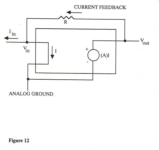
Fig 12 The last stage in the analog section of a CD player is the reconstruction filter stage. This stage removes the high frequency spectral components inherent in a sampled data system. The use of dig ital interpolation reduces the required or der of the analog filter stage consider ably. For an interpolation rate of 8x, a simple one-pole filter is adequate, al though most Japanese players (Sony, De non, Pioneer) use a third-order filter. The Onkyo DX-7500 offers the option of a first-order or a third-order filter. The Yamaha CDX-1120 has this option; however, a bipolar analog switch switches the filter in and out of the circuit instead of separate jacks for the two options. Only the passive components are bypassed in the CDX-1120, not the additional active stage. It is possible that the bipolar analog switch adds more distortion than is removed by shorting out the passive components. The higher-order filter is required if the preamplifier stage following the CD player is not linear outside the audio band. Most modern preamps should have no problem with the low order filter. Several designers of CD playback equipment disagree, finding that some otherwise excellent preamplifiers and power amplifiers require greater attenuation than a first-order system can provide. For this reason, Aragon uses a third-order Bessel filter. As stated above, the first-order filter can be incorporated in the current-to-voltage converter. Consequently, a single amplifying stage is used for the entire analog signal processing section. In addition to the Onkyo DX-7500, the Krell, PS Audio, and Theta digital decoders have a single analog stage. The Wadia goes even further, incorporating only RF filtering. If the output stage of the I/V converter is not robust enough, the settling performance of the I/V converter can be affected by the loading of the preamp and cables. This problem is most likely to occur with an I/V converter that uses only an integrated circuit. To prevent the settling time degradation, Theta and Wadia incorporate an additional buffer stage after the I/V converter. It is not possible to combine the current-to-voltage converter and the filter in one stage for all DACs. The problem arises in DACs with mismatched full scale current outputs (Burr-Brown PCM56P, PCM61P, Analog Devices AD1856 and AD1860). The mismatches are caused by processing variations in the values of the resistors at the DAC core. To match the voltage output between the two stereo channels at the output of the current-to-voltage converter, an additional monolithic resistor-which tracks the value of the resistors in the DAC's core-is used, since it is on the same die. When this resistor is incorporated in the feedback loop of the current to-voltage converter, the effects of the processing variations are canceled. Un fortunately, the absolute value of the feedback resistor varies between different dies, so it is incapable of forming a filter with a precise time constant. The current-to-voltage converter and first filter stage cannot be combined because of this, and an additional active gain stage is needed. CAL, Madrigal, Theta, and Kinergetics adopt the Burr-Brown PCM61P by carefully matching the current output of pairs of the DACs to obviate the need for an internal feedback resistor. This approach requires significant testing, and some working devices may not be usable if they cannot be matched to another DAC. All four DACs listed above have a built-in op amp which can form the current-to-voltage converter. The op amp on the PCM56P was not adopted by the Japanese in their mid priced and high-end products. The op amp on the Analog Devices may have better performance, since it is implemented in a more advanced (BICMOS) technology. The Burr-Brown PCMS8P has a laser-trimmed current source so its current output is matched between devices. The Philips TDA1541 has matched current outputs because both channels are on a single die. Unfortunately, the device can only work at a 4x interpolation rate, thereby requiring a third-order filter. To implement a third-order filter, two active stages, including the current-to voltage converter, are required. Mark Brasfield only uses a first-order filter in his TDA1541-based design. This creates a significant amount of high-frequency output from his player, centered around 176.4 kHz. Mr. Brasfield states that the level of these out-of-band signals is sufficiently low to render them inconsequential. Sony, Denon, and Onkyo use GIC based third-order filters in their more expensive players. The GIC (generalized impedance converter) filter creates high order (fifth or greater) filters which have low sensitivity to passive component variation. Accuphase used the GIC filter in its first CD player (the player did not use digital interpolation) to implement a high-order filter and achieved good results. Subsequently, the GIC circuit appeared in other CD players with low order filters under the assumption that the performance advantage of the GIC circuit would be retained. It is argued that the GIC circuit is not in the path of the analog signal as in the more standard Sallen-Key topology. The argument is flawed because a unity-gain buffer must follow the GIC filter. The Sallen-Key topology uses an identical unity-gain circuit, and the reactive components around the Sallen-Key filter are not in the circuit at audio frequencies. The GIC implementation requires two additional op amp stages and four additional passive components. A preferable approach would save the cost of these components by building a Sallen-Key stage with an improved op amp. Pioneer, in their PD-71, and Ken wood in the DP-8010 use a filter section which is formed around an op amp in the inverting configuration. This eliminates the common-mode distortion of an op amp when it is used in a buffer configuration. The disadvantage of this circuit is the added inverting stage which is required if absolute polarity at the output is to be retained. This can be accomplished with a simple digital circuit, though Pioneer chose an analog circuit. The circuit used by Pioneer and Kenwood also has the additional disadvantage of a low input impedance, which may be difficult for the previous stage to drive. The electrical requirements of the active voltage gain stage in a filter stage are similar to those of a preamplifier stage, except that the bandwidth of the stage should be wide enough to ensure proper operation of the filter in its stop band region. The PSRR (power supply rejection ratio) of the amplifier should be high at frequencies outside the passband, so that noise on the power supplies is not coupled to the output. The Sallen-Key filter circuit does not require a stage with voltage gain. Hence, a simpler unity-gain buffer can be used. Economics favor the design of a discrete buffer when compared with a discrete voltage gain stage. If it is uneconomical to use a discrete circuit in the filter section, a high-quality monolithic op amp or buffer should be used. Jung and Childress discuss the performance of a variety of op amps and recommend those that yield the best performance [Jung and Childress 1988], [Jung 1987]; they also discuss monolithic buffers [Jung and Childress 1988]. In addition to the active stage of the filter, the passive components of the filter can also affect sound quality [Jung and Marsh 1980]. The output from the reconstruction filter has a DC offset originating from both the active gain stage and any random or systematic DC offset in the DAC and/or the digital filter. The problem is not unique to CD players; preamplifiers and amplifiers also will have DC offsets at their outputs. This offset can be eliminated with a coupling capacitor. However, great care must be taken to ensure that the capacitor does not affect the sound quality of the signal. High-quality capacitors can be expensive and may not be available in large enough values to en sure a low enough cutoff frequency to provide the best possible bass response. As with the power supply, bypass capacitors and multiple capacitors of different types and values may be combined to yield the most transparent sound possible through the DC blocking stage. The alternative to a DC blocking capacitor-used by Theta, Precision Audio, Philips in the CD-80, and Onkyo in the DX-7500, among others-is a DC servo that nulls out the DC component from the output by placing a compensating DC voltage at the input of a stage that pre cedes the output [Clark 1982]. Unlike a coupling capacitor, a DC servo is, itself, not in the signal path. Hence, it does not affect the sound quality, provided it is de signed properly. The DC servo often is incorrectly described as allowing frequency response down to DC. The servo actually does not allow DC or very low frequency signals to pass to the output. If the DC servo fails, or a power supply rail collapses, or a circuit in the forward path of the servo fails, a 15 V or higher DC voltage will appear at the output of the CD player. A power amplifier or loud speaker can be readily destroyed if this failure mode occurs. A fail-safe protection circuit can be included, though only Philips among the above manufacturers has included the protection circuit. Jon Schleisner of Precision Audio argues that the chances of failure of the circuit are small. Further, he suggests that a large coupling capacitor provides a time constant of sufficient length to allow a 15 V pulse of over a second's duration to appear at the output of the CD player if the power supply or active circuitry should fail. This pulse could be of sufficient amplitude and duration to damage a power amplifier or speaker. The connection of the output of the DC servo to the analog stages in a CD player presents some difficulty when compared to its use in a preamplifier or power amplifier. Jung argues that the DC servo should not be terminated at the junction between the output of the DAC and the input of the I/V converter if the TDA1541 DAC is used [Jung and Childress 1988]. Jung reasons that the DC output drift during DAC warm-up and low-frequency noise present at the output of the DAC will cause problems. In contrast, Precision Audio and Philips, among others, terminate their servo at this junction and have reported no problems with the DC servo circuit. A CD may be encoded with digital data either flat in frequency response or emphasized with a high-frequency boost. The latter encoding requires a de emphasis filter at the filter stage so that the disc is played back with a flat frequency response. This additional filtering reduces the quantization noise present at the output of the DAC. The noise arises when the original data is quantized to 16 bits in the recording process. The de emphasis filter is usually implemented by placing a passive network across the feedback resistor of the current-to voltage converter or the first filter stage. This approach is problematic, since a sol id-state device is used as a switch and, consequently, nonlinear junction impedances of the device can affect the sound quality when the switch is off. The problem can be remedied by using a relay. Regrettably, in this application the relay must be of a high-quality design if reliability problems with the relay contacts are to be prevented [ Duncan 1988]. Some of the relays I have seen in CD players are not of high enough quality to overcome these reliability problems. An other problem with the placement of the de-emphasis network across the feedback resistor is instability arising from the re active components in the network. This can be resolved only by reducing the open-loop bandwidth of the amplification stage. A passive de-emphasis network placed between the current-to-voltage converter and the first filter stage has been employed by some designers to avoid compromising the amplification stage. A single analog stage cannot accommodate a passive de-emphasis circuit. Mark Brasfield believes the disadvantage of placing reactive components in a feedback loop outweighs the advantages of removing the second amplifier stage. Brasfield's CD players perform all filtering, including de-emphasis, passively so that no reactive components are in the feedback loop. The Phototronics PA630 chip also uses passive filtering and de-emphasis. The NPC SM5803 and Sony CXD1244 digital filters include an optional IIR filter to perform the de emphasis function. This eliminates the analog components required for the function. The disadvantage of performing the filtering in the digital domain is that quantization noise is still present at the output of the filter, since the signal has not yet been converted to the analog domain. This means that the advantage of the de-emphasis circuit is not fully realized. The problem becomes less significant for DACs with 18-bit linearity. The final design consideration is the muting circuit at the output of the CD player. This circuit prevents large voltage pulses from appearing at the output of CD player as it is powered on and off. These pulses can destroy an amplifier or speaker if they are not suppressed. The muting circuit places a short across the output of the CD player. This can be accomplished with a transistor or a relay. The relay is preferred, since the transistor will present a nonlinear impedance to the output when the muting circuit is not activated. The relay and its associated circuitry (which drives the relay) are obviously more expensive than a transistor switch. The relay, therefore, is found mostly in high-priced CD players. One exception is the midpriced Onkyo DX 7500. Some modifiers eliminate the transistor switch but do not replace it with a relay. They short out the power switch, letting the unit run continuously. This is a risky move, since a power interruption will cause pulses to appear at the CD player's output. If you are using a passive preamp and a power amp with a large supply filter bank, these pulses will appear at your speaker terminals and possibly destroy your speakers. For the best possible performance, it is desirable not to load the output of the CD player with a remote volume control circuit. Eliminating the remote volume control-as well as a headphone amplifier-helps keep PC board traces as short as possible, improving stereo separation. Eliminating rarely used features also lowers the cost of the player. Many modifiers disconnect these functions during the modification process, and high end CD players generally do not include them. Surprisingly, the Pioneer PD-71 also does not have these features-an un usual example of engineering considerations winning out over marketing considerations. Finally, four words regarding the remote volume control function: do not use it! These circuits are built to very low price points with cheap potentiometers and IC-based amplifiers. The line stage in your preamp should offer much better performance. If this is not the case, the purchase of a new preamp might prove worthwhile. Recommendations The October annual equipment issue of Audio magazine lists 80-odd different manufacturers and modifiers of CD play back equipment. Obviously, I have examined only a small sampling of these machines. This is particularly true in the low-priced category. One CD player I can recommend is the Magnavox CDB-630. The CDB-630 has a list price of $399.95 but is heavily discounted. This machine offers a mid grade (A) selection of the Philips TDA1541, a +15 V power supply, and a well-designed CDM-4 disc transport. While the CDB-630 is a good value at its price point, the plastic chassis, single sided phenolic printed circuit boards, extensive use of surface-mount components, and an abundance of plastic components in the CDM-4 are indications that the reliability of this player will not match that of the more expensive units. The CDB-630 is a favorite of the CD modifiers. Some modifiers replace the DAC with the S1 selection grade (and some do not!), add new power transformers, and nearly rebuild the analog section. The result is often a player with a four-digit price tag. Given the quality of construction and mission of the CDB 630, I recommend you avoid these modifications and purchase a better constructed CD player. Another low priced CD player which can be recommended is the Rotel RCD855. This unit uses the same basic parts as the Magnavox CDB-630, but according to the company it has upgraded power supply regulators, passive components, and improved op amps in the analog section. The RCD855 has fewer features than the CDB-630 and lists for $349.00. Rotel declined to send the unit for review. A final unit to consider in this price range is the Harman/Kardon HD7500, which sells for $449.00. [However, the Mark II version, which may be the only one avail able by the time you read this, costs $80 more.-- Ed.] A complete review of the Harman/Kardon HD7600, which is identical to the HD7500 except for features, is included in this issue. The Philips CD-80 ($799.95) is a much better value than any modified Magnavox can offer. The best selection grade (S1) of the TDA1541A is combined with an all-discrete power supply regulation system. The unit uses a metal chassis and the CDM-1 Mk II transport, which has far fewer plastic components. A full review of the CD-80 is in this issue. Most modifiers give nebulous excuses for their preferences in using the Magnavox CDB-630 rather than the Phil ips CD-80 as the foundation of their modifications. You might consider buying a CD-80 if $800 is the maximum you want to spend on a CD player, and later go to a modifier service to have it up graded when your cash flow position improves. I think this two-step purchase approach is the best reason to consider buying a modified player over one that has been designed from scratch. The modifier offers you a CD player in the $1000 to $1500 price class even if you cannot afford it in one purchase. You might also consider having a modifier such as Paul McGowan Designs or Precision Audio modify your current CD player provided it is well-built and has a linear DAC. The discontinued Philips CD960 and Sony CDP-910, 705ESD, 605ESD, and 505ESD are also good candidates. If you have an older Philips based player with a 14-bit DAC (CAL Tempest I, Kinergetics KCD-20A, etc.), Digital Upgrades offers a modification which replaces the digital filter with the NPC SM5813 and the DAC with the Analog Devices AD1860-K. At $300 this upgrade is a good value for owners of these older CD players, provided the transport mechanism is in good condition. Given the quality of performance available from the PS Audio "Digital Link" (see below), I suggest that you spend no more than $400 on the modification of a CD player. CD players using the Burr-Brown PCM58P or PCM61P in its selected grade should also be considered. The Onkyo DX-7500 ($700.00), Pioneer PD-71 ($850.00), and Sony CDP 608ESD (900.00) are all excellent players and highly recommend. Each of these units has distinct advantages and disadvantages, which are discussed in full reviews in this issue. Again, successor models exist in the case of the Pioneer and the Sony, but the similarities are much greater than the differences.- Ed.] These units, for a variety of technical reasons, may be more difficult to modify than the Philips CD-80. If you are contemplating having the units modified at a later date, you might want to talk to the modifier before purchasing the base unit. You should also look at the CAL Icon at $750.00. According to the manufacturer this unit is DC coupled and uses the PMI OP42 op amps. I have not examined this unit and cannot make a firm recommendation. The recent release of separate digital-to-analog converter boxes is very good news. Complete reviews of the Aragon D2A and PS Audio "Digital Link" are in this issue. I can recommend both units. You should not choose the Aragon unit if you are using a passive preamp (see the full review). Both Aragon and PS Audio have made provisions in their designs to allow updating to new DACs and filter chips. The ability to update these boxes is an advantage over a high end all-in-one CD player. (Aragon and PS Audio have not yet announced an up grade to the Burr-Brown PCM63P or Analog Devices AD1862. | hope these companies will keep the promise to upgrade their products.) The major disadvantage of a decoder box is increased time-base jitter from the SPDIF interface. I could not evaluate the Proceed PDP decoder box ($1295.00) because the manufacturer, Madrigal Audio Laboratories, refused to a send a schematic (or, in deed, a unit for review). Based on the limited information I have, [ cannot see a justification for spending $300 more than the price of the Aragon or $496 more than the price of the PS Audio on this unit. As for the ergonomic problems of the Meridian 208 (see the full review in this issue), they do not exist in the Meridian 203 decoder box ($990.00). The unit was introduced too late to be re viewed along with the 208, but at least it is more realistically priced. The analog section is similar to that of the 208 and thus lacks the level of sophistication found in the Aragon and PS Audio units (the NE5534 op amp is used, for example). Also the 203 uses the obsolescent SAA7321 DACs. The only circumstance under which I would recommend this unit would be the availability of an up grade path to the SAA7350 (or at a minimum the SAA7323). To my knowledge, such a program has not been announced. At a higher price point, you might consider examining the new Theta DS Pro Basic decoder ($2000.00) and the Wadia DigiMaster X-32 ($1995.00). Both decoders use a digital filter implemented on a general-purpose DSP chip set. Both represent good value given the sophistication of the technology used in these units. The "Pre" version of the Theta receives a full review in this issue. Wadia declined to send the unit for re view. The Wadia unit uses a time-domain algorithm. This algorithm causes a high frequency roll-off and results in a high level of out-of-band energy at the unit's output. Others' reviews of the Wadia have shown very nonlinear DACs. The principal advantages of the DigiMaster X-32 are the excellent jitter performance of the RockLok clock recovery circuit and the ability to reconfigure the glue logic and SPDIF decoder with PROM chips. Overall, I think the disadvantages are greater than the advantages. Given the steady rate of improvement in CD player technology, I cannot recommend spending more than $2000 for any CD player or decoder. Acknowledgement Thanks are extended to Dr. Stanley Lipshitz and to Rex Nathanson for their careful review of the manuscript and their perceptive commentary. References Ainslie, A. "What Is Noise Shaping?" Hi-Fi News & Record Review (February 1990): 45. Allgaier, Jr., J. "Greening Magnavox 14-Bit CDs." The Audio Amateur 19.4 (October 1988): 19-23. Ardalan, S. and J. Paulos. "An Analysis of Nonlinear Behavior in Delta Sigma Modulators." IEEE Transactions on Circuits and Systems CAS-34 (June 1987): 593. Borbely, E. "A Moving Coil Pre amp." The Audio Amateur 18.1 (January 1987): 30. Borbely, E. "A Multi-Tone Inter modulation Meter." The Audio Amateur 20.2 (April 1989): 7-15; 20.3 (August 1989): 13-29. Breakall, J., R. Simons, and F. Me rat. "Measuring Power Supply Output Impedance." The Audio Amateur 14.2-3 (April and June 1983). Burr-Brown IC Data Book. Vol. 37. Burr-Brown Research Corp., 1989. Carley, L. "An Oversampling Ana log to Digital Converter Topology for High-Resolution Signal Acquisition Systems." IEEE Transactions on Circuits and Systems CAS-34 (January 1987): 83. Cezanne, J. and A. Papoulis. "The Use of Modulated Splines for the Reconstruction of Band-Limited Signals." IEEE Transactions on Acoustics, Speech, and Signal Processing 36.9 (September 1988): 1521. Cherry, E. M. "Feedback, Sensitivity, and Stability of Audio Power Amplifiers." Journal of the Audio Engineering Society 30 (May 1982): 282-94. Cherry, E. M. "Amplitude and Phase of Intermodulation Distortion." Journal of the Audio Engineering Society 31 (May 1983): 298-304. Clark, B. "DC Servo Loop Design for Audio Amplifiers." The Audio Amateur 13 (August 1982): 14. Colloms, M. "Wadia 2000 and 1000 Processors." Hi-Fi News & Record Re view (December 1989): 49-53. Colloms, M. "Krell Digital MD-1/ SBP-64X/SBP-16X." Hi-Fi News & Record Review (June 1990): 58-63. Cordell, R. R. "Another View of TIM." Audio 64.3 (March 1980): 39. Cordell, R. R. "Phase Intermodulation Distortion Instrumentation and Measurements." Journal of the Audio Engineering Society 31 (March 1983): 114 23. Didden, J. M. "Wideband Power Supply." The Audio Amateur 18.1 (January 1987): 22. Didden, J. M. "A Simple, High Quality CD Output Amp." The Audio Amateur 20.2 (April 1989): 26-31. Dijkmans, E. C. and P. J. A. Naus. "The Next Step Towards Ideal A/D and D/A Converters." The Proceedings of the AES 7th International Conference: Audio in Digital Times (May 1989): 97-103. Duncan, B. "Super-tuning CD." Hi Fi News & Record Review (November and December 1987, January 1988, and March 1989). Duncan, B. "Evaluating Audio Op Amps." Studio Sound (July, August, and September 1990). Duncan, B. "Building Bitstream." Hi-Fi News & Record Review (September and October 1990). Evans, S. "Design Entry." Electronic Design ( 28 November 1985): 125. Fielder, L. D. "Human Auditory Capabilities and Their Consequences in Digital Audio Converter Design." The Proceedings of the AES 7th International Conference: Audio in Digital Times (May 1989): 45-62. Fourre, R. D. "Testing 20 Bit Audio Digital-to-Analog Converters." The Proceedings of the AES 7th International Conference: Audio in Digital Times (May 1989): 79-80. Gardner, F. Phaselock Techniques. 2nd ed., Chapter 6. John Wiley and Sons, 1979. Goodenough, F. "Design Innovation." Electronic Design ( 16 April 1987): 59. Goodenough, F. "New Processes, Designs Boost IC Op Amp Speeds." Electronic Design ( 12 April 1989): 45. Goudie, A. "Idle Tones in Oversam pled ADCs." 87th Convention of the AES, New York, NY (18-21 October 1989): Preprint 2882. Harris, S. "The Effects of Sampling Clock Jitter on Nyquist Sampling Ana log-to-Digital Converters and Oversam pled Delta Sigma ADCs." 87th Convention of the AES, New York, NY (18-21 October 1989): Preprint 2844. Howe, T. "Stretching Marsh's Pre amp." The Audio Amateur 20.1 (February 1989): 29-37. Jensen, D. "JE-990 Discrete Operational Amplifier." Journal of the Audio Engineering Society 28 (January/Febru ary 1980): 26-34. Jung, W. and R. Marsh. "Picking Capacitors." Audio 64.2-3 (February and March 1980). Jung, W. "Op Amp Meets CD." The Audio Amateur 17.3 (August 1986): 7. Jung, W. Audio IC Op Amp Applica tions. 3rd ed. Howard W. Sams, 1987. Jung, W. and H. Childress. "POOGE 4: Philips/Magnavox CD Player Mods." The Audio Amateur 19.1 (February 1988): 7-17; 19.2 (May 1988): 19. JVC. " K2 Interface." JVC Company of America, 1989. Lee, K. and R. Meyer. "Low Distortion Switched-Capacitor Filter De sign Techniques." IEEE Journal of Solid State Circuits 20.6 (December 1985): 1103. Lipshitz, S. P. and J. Vanderkooy. "Are D/A converters Getting Worse?" 84th Convention of the AES, Paris, France (1-4 March 1988): Preprint 2586. Marsh, R. N. "Power Up: An Over view of Power Supply Considerations." The Audio Amateur 14.4 (September 1983): 16. Marsh, R. N. "Low-Distortion, Low-Feedback Power Amplifiers." The Audio Amateur 16.3 (July 1985): 24. Matsuya, Y., K. Uchimura, A. Iwata, and T. Kaneko. "A 17-bit Oversampling D-to-A Conversion Technology Using Multistage Noise Shaping." IEEE Journal of Solid-State Circuits 24.4 (August 1989): 969. McGillen, C. and G. Cooper. Continuous and Discrete Signal and System Analysis, 159. Holt Rinehart and Wins ton, 1974. Miller, P. "Resonance and Repercussions." Hi-Fi News & Record Review (June 1989): 35. Millman, J. Microelectronics, Chapter 12. McGraw-Hill, 1979. Moses, R. W. "Improved Signal Processing for Compact Disc Audio Systems." MONTECH °'87 Proceedings: Conference on Communications (9-11 November 1987): 203-11. Naus, P. J. A,, E. C. Dijkmans, E. F. Stikvoort, et al. "A CMOS Stereo 16-Bit Converter for Audio." IEEE Journal of Solid-State Circuits 22.3 (June 1987): 390. Naus, P. J. A. and E. C. Dijkmans. "Low Signal-Level Distortion in Sigma Delta Modulators." 84th Convention of the AES, Paris, France (1-4 March 1988): Preprint 2584. Nethisinghe, S. S. Introduction to Bit Stream A/D, D/A Conversion. Philips Components, 1988. Otala, M. and R. Ensomaa. "Transient Intermodulation Distortion in commercial Audio Amplifiers." Journal of the Audio Engineering Society 22 (May 1974): 244-46. Otala, M. "Feedback-Generated Phase Nonlinearity in Audio Amplifiers." 64th Convention of the AES, London, England (25-28 February 1980): Preprint 1576. Papoulis, A. Circuits and Systems: A Modern Approach, Chapters 6.3, 7.4, and 8.3. Holt Rinehart and Winston, 1980. Papoulis, A. Probability, Random Variables and Stochastic Processes, Chapters 11.2 and 13. McGraw-Hill, 1984. Pryce, D. "Audio DACs Push CD Players to Higher Performance." EDN ( 7 December 1989): 112. Rumsey, F. "AES/EBU Interface Comes of Age?" Studio Sound (December 1989): 29 Stikvoort, E. F. "Higher-Order One Bit Coder for Audio Applications." 84th Convention of the AES, Paris, France (1 4 March 1988): Preprint 2583. Texas Instruments. Linear Circuits: Data Acquisition and Conversion. Data Book, Volume 2. Texas Instruments Incorporated, 1989. Vanderkooy, J. and S. P. Lipshitz. "Dither in Digital Audio." Journal of the Audio Engineering Society 35 (December 1987): 966-75. Vanderkooy, J. and S. P. Lipshitz. "Digital Dither: Signal Processing with Resolution Far Below the Least Significant Bit." The Proceedings of the AES
Table 1: Design Features of CD Players and Separate D/A Converters SPDIF Digital D/A Interpolation Sample and Analog ItoV Decoder [1] Filter Converter Rate Hold Circuit Stages Converter [1] Applicable only to outboard con verter boxes and digital preamplifiers. [2] Total number of regulators in unit (outboard converters naturally require a smaller number than complete CD players [4] General-purpose DSP (digital sig or digital preamplifiers). nal processor) with custom software. [3] Balanced operation with 2 DACs [5] A proprietary configuration allows per channel. one SAA7321 to be used in each channel. ------ (Blank space signifies unavailable data. See review section for successor models, if any. ) [6] Only the PLL phase detector is integrated on this chip. [7] Clock signal is internally generated when used with Sony CDP-R1 transport.
[8] Staggered configuration with 2 DACs per channel provides 2x increase in conversion rate. [9] External adaptive PLL filter is used. Crystal oscillator is stopped when phase lock is achieved. [10] Bit shifting circuit is used after the DACs. 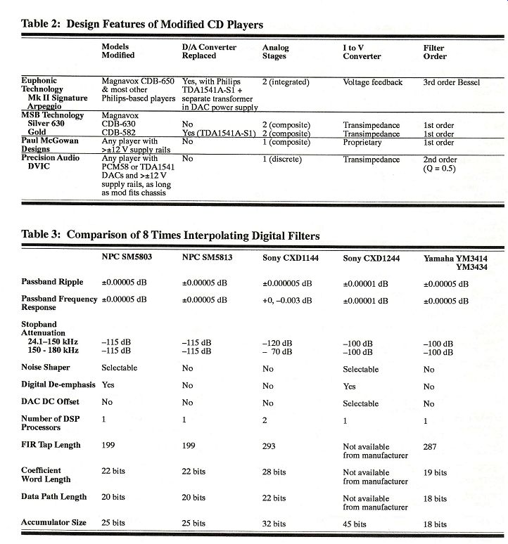
---------- Table 2: Design Features of Modified CD Players ----------- Table 3: Comparison of 8 Times Interpolating Digital Filters References 7th International Conference: Audio in Digital Times (May 1989): 87-96. Wadsworth, D. C. "A Professional Audio Integrated Circuit." 87th Convention of the AES, New York, NY (18-21 13.10 (October 1990): 59. October 1989): Preprint 2831. Willenswaard, P. van. "Industry Update: The Netherlands." Stereophile
Williams, J. "Designer's Guide to Op-Amp Booster Stages." EDN ( 29 May 1986): 131. 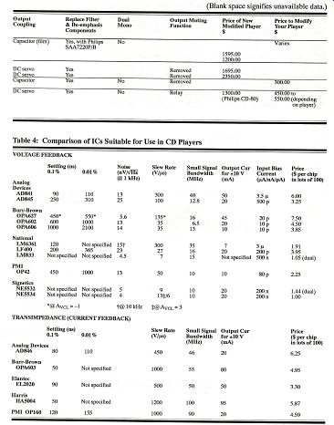
---- (Blank space signifies unavailable data.) Table 4: Comparison of ICs Suitable for Use in CD Players; TRANSIMPEDANCE (CURRENT FEEDBACK) --------------- Designing the Analog Stage Analog stage design in a CD player is similar to preamplifier stage design. The functional first section of the analog stage, namely the current-to-voltage converter, is the most difficult to design. The current-to voltage converter takes the current output of the DAC as its input and generates a voltage signal at its output with a level linearly proportional to the current entering the stage. Design problems arise in this stage because the DAC output is not a bandlimited analog signal, but rather a set of current steps changing at the word rate of the DAC. The stage must respond to the step change in current with a step change in voltage. The voltage change must occur within a small percentage of the conversion period, and the voltage output must settle to the new signal within an accuracy of 0.0015% (for 16-bit accuracy) of the output expected from an ideal current-to-voltage converter. To achieve this level of performance, the amplifier must have a high slew rate, a wide bandwidth, linear operation with "large-signal" inputs, and large stability margins. As an example of the requirements in a current-to-voltage converter, consider the required slew rate for an amplifier to slew completely from the maximum positive signal to the maximum negative signal (a swing of 5.6 V typically) in one-tenth the conversion period of the DAC. For an 8x interpolating system this is 285 ns. A slew rate of at least 20 V/us is required. To settle within 0.0015% of a signal's final value, a circuit with a single-order lowpass response must settle in 11 time constants. This requires the current-to voltage converter to have a bandwidth 11 times the word rate. For an 8x interpolating system, this requires the current-to-voltage converter to have a bandwidth greater than 4 MHz. To ease these requirements some what, a first-order filter function, which forms part of the reconstruction filter, can also be incorporated in the current-to voltage converter. An additional operating constraint requires that the input of the current-to-voltage converter be held at its ground potential so that the DAC is terminated into a virtual short. If the output of the DAC is not held at a constant ground potential, the linearity of the converter is degraded. The current-to-voltage converter should also show good rejection of high frequency noise, which may be present on the power supply rails. A current-to-voltage converter stage should have a minimum power supply rejection ratio of 60 dB at 100 kHz. A current-to-voltage converter can be crafted from a voltage amplifier [Jung 1986], though the performance criteria are more easily met using a current feedback (transimpedance) amplifier [Evans 1985], [Goodenough 1987]. This topology offers higher slew rates, greater bandwidth, and lower settling times than is possible with an op amp topology. This circuit is more easily understood than the op amp circuit. It, therefore, will be used as a point of reference in explaining the operation of a current-to-voltage converter stage. The trans-impedance amplifier (Figure 12) works by placing a low impedance across the input to act as a short. This forces the input voltage V_in to be held at ground potential as required for proper D/A performance. Feedback, in the form of current, is applied to the input through R. Current from the DAC and current from the feedback branch enter the short-circuit input of the transimpedance amplifier. The gain stage, whose transfer function is A (with units in ohms), senses the current in the short and transforms it into a voltage. If A is large enough, the feedback loop will be satisfied when the current feed back is equal to the input current. Since the input node is held at ground potential, the voltage output of the stage is the voltage across the resistor. Hence, Vout = ink This is the ideal equation for a volt age-to-current converter with conversion impedance R. If the designer has chosen to reduce the amount of negative feedback in an audio amplifier, the transimpedance amplifier has an additional advantage. Cordell argues that an amplifier can be designed with high global feedback rates and avoid exhibiting dynamic distortion [Cordell 1980]. D. C. Wadsworth of Phototronics contends that this argument is valid only if the input signal is bandlimited to the audio band. The input to a current-to-voltage converter has a bandwidth well into the megahertz region, thereby violating this condition. A voltage amplifier, when used in a current-to-voltage converter, requires high rates of feedback to reduce the input impedance of the amplifier [Millman 1979] to a point at which the DAC output will not move significantly from ground potential. Only transimpedance amplifiers and current amplifiers-see [Didden 1989] for an elegant treatment of a current amplifier as part of an I/V converter stage-are feasible if a low rate of negative feedback is to be used around an amplifier which simultaneously provides a low input impedance. The principal disadvantage of current-mode amplifiers is that they are not as easy to use as op amps [Goodenough 1990]. Increased noise levels are also a potential problem with current-mode amplifiers. Accuphase, Precision Audio, Barclay Audio (a company no longer producing complete CD players), and M. S. Brasfield adopt transimpedance amplifiers in their respective current-to-voltage conversion stages. Interestingly, the latter three are small American companies with degreed electrical engineers heading the design department. All three companies developed the solution independently. Small CD modifiers who do not have an engineering back ground continue to use op amps in their de signs. Unfortunately, no matter how many different types of op amps they try, they will never overcome the fundamental de sign problems understood by trained professionals. A designer who has chosen to use integrated circuits in the analog stages now has the option of using an integrated circuit de signed specifically for high-end and professional applications. The chip is the Phototronics PA630 current conveyor, designed by D. C. Wadsworth [ Wadsworth 1989]. The current conveyor (patents pending) is a special form of current amplifier that re quires no global feedback. Output buffers included on the chip for filtering functions (see below) also use no global feedback. The chip is processed using an advanced (and expensive) complementary bipolar process. All passive components are left off the IC so that high-quality discrete passives can be used. No short-circuit protection, which could introduce nonlinearity and increase settling time, is included. Because the entire circuit is implemented on a single chip, the rise time of the current conveyor is less than 25 ns. Since no global feedback is used, THD is an order of magnitude (0.02% at 0.5 V rms) higher than that for circuits that use even moderate levels of global feedback. The level is still low enough to be almost certainly inaudible. The chip also has fairly low power supply rejection; consequently, it requires good supply regulation. These chips are priced higher than standard op amps because of the advanced processing technology. In addition, new monolithic devices must be priced high enough to cover the cost of their development phases. Older IC devices are priced closer to the direct cost of manufacturing. The price of the PA630 will re strict its use in budget machines, but mid priced machines should be able to incorporate these devices. A number of high-performance monolithic current feedback amplifiers have been recently introduced to the market. The principal specifications for these op amps are given in Table 4. Unlike the PA630, these chips are not specific to CD players. They offer lower THD levels, though dynamic distortion products may result. Two provisos: these wide-bandwidth IC devices can be difficult to work with and will oscillate if not properly employed. For this reason, I do not suggest that you attempt to replace the op amps in your present CD player with current feedback amplifiers. A few low-noise, high-slew-rate, wide-bandwidth monolithic operational amplifiers can be used with good results in the current-to-voltage conversion stage if a designer chooses to implement the current to-voltage converter with op amps. Jung uses the op amp's offset adjustment pins in an innovative manner to linearize the first stage of some op amps [Jung 1986]. This raises the linear input range and lowers the global feedback rate by forming an inner feedback loop around the first stage of the amplifier. A relatively inexpensive Signet ics NES30 op amp is used so that the circuit can create a current-to-voltage converter with good performance in a popularly priced CD player [Jung and Childress 1988]. A popular opamp used in some high-end CD players as a current-to voltage converter is the PMI OP42. The performance of the OP42 and of some more recently introduced op amps is given Table 4. As can be seen, the OP42 is an excellent choice for cost-sensitive applications. Table 4 also gives the performance data for the NE5532, NE5534, and LM833 op amps used in most European and Japanese CD players. As can be seen from the chart, these devices do not meet the 20 V/us slew rate requirement calculated above. Furthermore, the critical specification of settling time is not disclosed for these chips. Manufacturers often state that they are forced to use these op amps be cause they have lower noise than higher speed devices. As can be seen from the chart, this objection is substantiated, with the exception of the Burr-Brown OPA627. The reduction in the signal-to-noise ratio that would result if the other high-speed op amps were employed is an insignificant 9 to 12 dB-insignificant because all of them exceed the inherent signal-to-noise ratio of a 16-bit digital encoding system, which is 98.1 dB and therefore the effective limiting parameter. If this reduction is not accept able, a high-speed op amp can be used in conjunction with a simple discrete preamplifier to form a low-noise, high-speed amplifier. As an example, the data sheet for the SSM-2210 transistors shows an amplifier with a 1.7 nV/V/Hz noise level, 40 V/us slew rate, and 63 MHz bandwidth. The noise level of this amplifier is lower than that of any commercial op amp. Mike Moffat of Theta uses the PMI OP42 operational amplifier in his designs. Mr. Moffat claims that the use of Teflon PC boards (which are extraordinarily expensive) makes a significant difference in sound quality. [Ahem.-Fd.] A discrete de sign would take up too much board space to allow the use of a Teflon PC board, Mr. Moffat argues. Mr. Moffat states that an op amp-based analog stage will outperform a discrete stage on a cheaper PC board. Mr. Moffat also states that a current feedback amplifier, while exhibiting fast settling to 10- or 12-bit accuracy, may not settle as quickly to 16-bit accuracy as the OP42. --------- [adapted from TAC 15, Spring through Winter 1990-91 ] --------- Also see: Current CD Players and D/A Processors, New and Not So New, Multibit and One-Bit, By Peter Aczel, Editor and Publisher Various audio and high-fidelity magazines Top of page |
|
| Home | Audio Magazine | Stereo Review magazine | AE/AA mag. |