AMAZON multi-meters discounts AMAZON oscilloscope discounts
Because of their lack of microphonics and hum, transistors are a natural for audio amplifiers. The low-level stages of an audio amplifier are critical, because noise, hum, or distortion will be carried through the system and amplified ( along with the desired signals) at the output. Hum in vacuum tubes comes from the use of AC as the heater source, or sometimes from a power supply with poor filtering. Thus, the fact that transistors use no AC, means that hum-free operation can be achieved.
Microphonics is a form of noise caused by vibration of the tube elements. This creates an undesired modulation of the signal; with transistors, however, there is no distortion because semiconductor circuit elements are secure, and hence do not vibrate.
Low-output impedance is another advantage of power transistors in audio amplifiers. Transformers which drive speakers are responsible for many problems in the circuit design of audio amplifiers, because of their inherent frequency limitations plus their size and weight. However, power transistors can drive the voice coil directly, because of the close impedance match; no output transformer is needed.
The low current drain and small size of transistors makes them extremely popular for use in portable equipment. With small components, a lightweight battery source, and four- to six-inch speakers, the entire audio amplifier makes a tiny package. Transistors are also found in preamplifiers, intercoms, and other normally non-portable equipment.
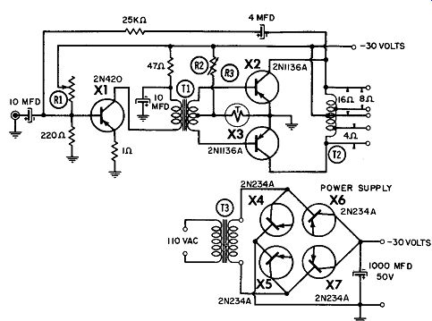
------------143 20-watt Hi-Fi amplifier.
T, - E-11 (4% Silicon Steel)
Square Stack - 7 /a in.
Window Area - 0.574 sq. in.
Cross Sectional Area - 0.766 sq. in.
Primary - 450
Turns #28E
Secondary - 250 Turns #28E ct Ta - Stancor RT204 T2 - E-12 (4% Silicon Steel)
Square Stock - 1 in.
Window Area - 0.75 sq. in.
Cross Sectional Area - 1 sq. in.
366 Turns #18E 183 Turns Tap for 160 (also ct) 92 Turns Tap for 80
20-WATT HI-Fl AMPLIFIER
This is a three-transistor hi-fi amplifier with a response of ± 1 db from 50 hz to 20 khz, and +2 db from 20 hz to 20 khz. Harmonic distortion is 0.8% at 1 watt and 2.7% at 20 watts ( at 1,000 hz). This power amplifier can be used with a suitable pre-amplifier to obtain 20 watts of output. With the transformer, output impedances of 4, 8, and 16 ohms are provided. A single 30-volt power source, plus a bridge using four low-cost power transistors as diodes, are required. These transistors are efficient in this application because of their low forward voltage drop.
2-WATT HI-Fl AMPLIFIER
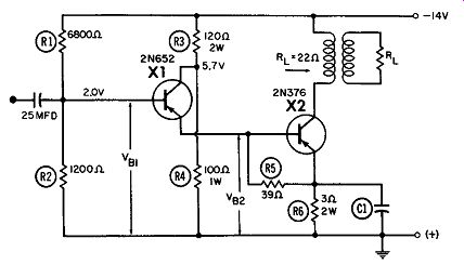
---------- 2-watt Hi-Fi amplifier.
In this circuit, a 2N652 emitter follower driving a 2N376 power transistor allows maximum amplification with a minimum amount of distortion. A single 14-volt supply is used; and R1 and R2 form the bias network for both stages.
Because the emitter current of X1 is the sum of both the currents of R5 and the X2 base, the emitter current of X1 will be maximum when the lowest-gain transistors are used for X2. R3 and R4 are chosen so that the minimum VcE is about one volt during peak signal conditions. Operating X1 at the lowest possible voltage will increase the stability, resulting in less power dissipation.
R6 determines the stability of the system and the variation in current gain of X2. The voltage drop across R6 should be larger than the changes in base-to-emitter voltage required to keep the emitter current constant over the expected temperature range for the various transistors.
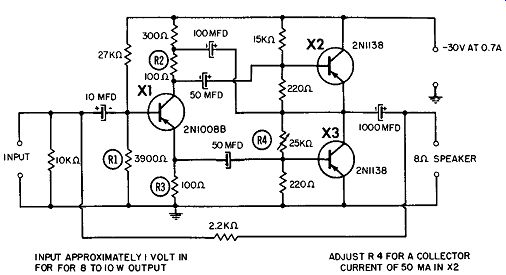
------------------ Low-cost Hi-Fi amplifier.
LOW-COST HI-Fl AMPLIFIER
Here is a low-cost hi-fi amplifier using only three transistors and a single 30-volt supply. With a signal input of 1 volt, the out-put will be approximately 8 to 10 watts. The power gain of the amplifier is approximately 20 db.
The first amplifier ( X1 ) is used as a phase inverter to feed the bases of X2 and X3, which are operated in push-pull. Stabilizing feedback is obtained through the 2.2K resistor at the speaker tap.
Having no inductive components, the circuit has an almost flat response over a wide audio spectrum.
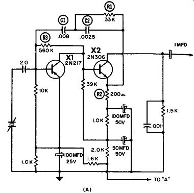
-------------- (A) Preamplifier.
--------------
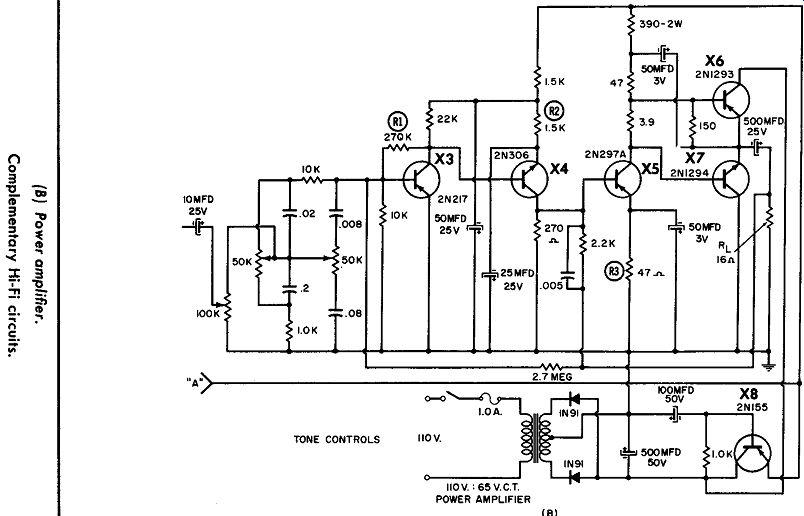
COMPLEMENTARY HI-Fl CIRCUITS
Complementary hi-fi circuits are very useful in resistance coupled applications. Some of the benefits of the cascade complementary amplifier are higher current gain, better temperature stability, and component interchangeability and economy. Part A shows a preamplifier for a ceramic pickup. Frequency stabilization is accomplished by the negative feedback of C1, R1, and C2.
DC stabilization is provided by R2 in the emitter of X2, and R3 in the collector of X1. The main amplifier is shown in Part B. DC stabilization is accomplished by the RI collector-to-base resistor of X3, the R2 emitter resistor of X4, and the R3 emitter resistor of X5. The output stages are operated Class B, and the driver is operated Class A. Feedback reduces distortion and the output impedance.
The complete amplifier is rated at 10 watts with noise down 65 db, and the frequency response is 30 hz to 15 khz ± 1.5 db.
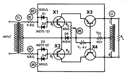
--------------- 125-watt class-B push-pull amplifier.
T1 - Input transformer - driving source impedance should be 10 to 20 ohms - 0. C. resistance in range of 2 to 4 ohms b - Output choke or transformer as required.
Amplifier is designed to deliver 125 watts into 19.6-ohms collector-to-collector of Q s and Q4 (4.9 ohms collector-to-center tap)
125-WATT CLASS-B PUSH-PULL AMPLIFIER
This high-power Class-B audio amplifier uses tetrode 3N47 or 3N51 transistors in a common-emitter push-pull stage for high power gain and frequency response at low voltage. A pair of 2N57 4A transistors in a common-base arrangement are utilized for the 125-watt output.
A separate 4-volt supply is used for the first stage. The voltage divider bias network is formed by R3, R1, and the DC resistance of half the secondary of T1. The value of R3 may have to be changed to maintain the collector current if a transistor with a much different gain is used. Diodes D1 and D2, in series with base 1 of transistor X1, block the reverse drive during the off half-cycle.
This reduces the high-frequency distortion.
Reverse bias is applied to B2 of X1 through potentiometer R5.
This voltage is obtained from the forward voltage drop across silicon power diode D5. By adjusting R5 while observing the total harmonic distortion of the amplifier, it is possible to obtain the desired minimum distortion ( balanced output currents from X1 and X2).
Drive for X1 and X2 is obtained from the tapped secondary of T1. The collectors of the first stage drive the emitters of the second stage; the 40-volt source is supplied through the output-choke center tap.
The low-voltage source supplies 400 mils peak, and the 40-volt source provides 7.15 amperes peak.
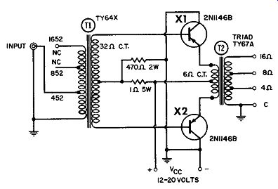
100-WATT AMPLIFIER
This diagram shows a two-transistor ( 2Nll46B) audio amplifier featuring circuit simplicity.
At a 1-watt input, the power source is 12 volts, output power is 30 watts, and the response is flat (within 3 db) from 25 hz to 14 khz.
With 2 watts of input, the power source is 15 volts, output power is 50 watts, and the response is 30 hz to 11 khz.
At 3.8 watts in, the power source is 20 volts, output power is 100 watts, and the response is 50 hz to 17 khz.
--------- 100-watt amplifier.
10-WATT AMPLIFIER
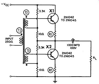
Use of the 2Nl042-45 series transistor as an audio amplifier is shown in this figure. The transistors are in push-pull, since the emitter signals are 180° out of phase ( as shown on the diagram by the dots at each end of the transformer). Using the 2Nl042, for example, with a -35-volt supply and a 1-ohm emitter resistor, the efficiency is 58% for a 10-ohm load and the distortion is 2.7%.
------------- 10-watt amplifier.
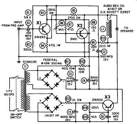
------------- 5-watt class-A amplifier.
Other transistors with larger supply voltages and lower efficiencies are listed in the table.
5-WATT CLASS-A AMPLIFIER
Using a 2Nl263 driving a tetrode 3N51, this audio amplifier produces more than 5 watts of output at a low ( 1.5% ) distortion.
The driver is a common emitter with a voltage divider R1-R2 to provide a DC collector current of 100 ma.
The output stage is a common emitter. Base 2 of the tetrode is connected to a reverse-biasing source consisting of a 6-volt sup ply and a 220-ohm series resistor. Base 1 is forward-biased in the conventional manner with a 1,000-ohm potentiometer R6 connected to a 12-volt collector supply. The combination of these forward- and reverse-biasing networks establishes a quiescent (no-signal) collector current of 1.2 and 1.4 amperes DC. The input signal is divided between the two base connections by means of a fixed 47-ohm and a 150-ohm resistor network.
The coupling between the output stage and load is relatively simple and straightforward. The collector of the output stage is shunt-fed through a low DC resistance choke. For the collector supply voltage and quiescent current used, maximum power output is obtained with an 8- to 10-ohm load across the collector to-emitter junction of the output stage. A 50% reduction in power output results when 5- or 20-ohm load resistances are used, but a tapped choke will permit maximum power output into load resistances of 4, 8, or 16 ohms.
7-WATT AMPLIFIER
This figure shows an RC coupled 7-watt audio amplifier in which six transistors are used. The 4-, 8-, or 16-ohm voice coil can be driven directly by the output stage. Hence, no output trans former is needed.
Level control 5K is used to adjust the volume, and bias control R2 helps control the circuit distortion. After amplification in X1 and X2, the signal is split into two paths by X3 and X5. At these stages, the signal is injected into push-pull amplifier X4 and X6, and a full 7 watts is obtained at the output.
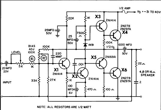
------------- 7-watt amplifier.
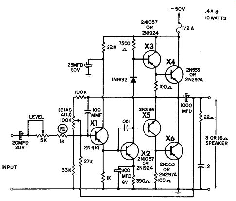
--------------- Direct-coupled 10-watt amplifier.
DIRECT COUPLED 10-WATT AMPLIFIER
This is a typical 10-watt audio amplifier featuring a Bias and Volume control. No output transformer is needed. Direct coupling through a 1,000-mfd capacitor is sufficient to drive an 8- or 16-ohm PM speaker.
About 6 db of negative loop feedback is used to match the output impedance of the amplifier to the load and further reduce distortion. The feedback path consists of a 270-ohm resistor connected between the collector of the output stage and the emitter of the driver stage. This path includes the emitter current of the driver stage. Because there is practically no phase shift be tween the emitter and collector currents of this stage in the useful passband of the amplifier, the phase shift around the feedback path is essentially that of the output stage only.
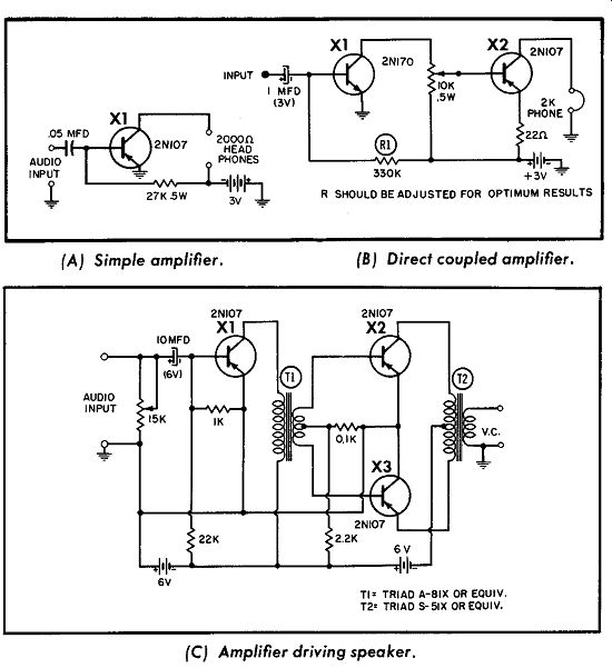
---------- Basic audio circuits. (A) Simple amplifier. (B) Direct coupled
amplifier. (C) Amplifier driving speaker.
BASIC AUDIO CIRCUITS
Many types of audio amplifiers are possible using a wide variety of transistors. Three basic circuits are shown here. Part A of the diagram is an elementary circuit that can be used with an RF detector to provide audio to drive a pair of earphones. Input is to the base of the 2Nl07, which operates with a grounded emit ter. A single 27K, 0.5-watt resistor is used for bias, and the output is taken off through the 2,000-ohm phones.
Part B shows a "battery saver," which has a low current drain and uses direct coupling from the 2N170 to the 2N107.
Unlike Parts A and B, which use phones for the output, Part C uses a speaker. Note that two 6-volt sources are employed in the transformer-coupled circuit of Part C.
PHONO TAPE PREAMPLIFIER
This three-transistor preamp is designed to produce a signal level of 1 to 2 volts from the low-level signal input and, at the same time, provide compensation for that signal. The total harmonic distortion is less than 2% , and either magnetic tape or magnetic pickups can be used for the input. Feedback resistor R2 is adjusted to provide 2 volts at the collector of XL Part B of the diagram shows the output response curve. With treble control R12 in mid-position, there is a flat response for standard RIAA recording and NARTB prerecorded tapes. A boost of 8 db is obtained with the full 25K in the circuit, and the treble reduction is 2 db with R12 at zero.
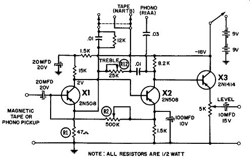
-------------153 (A) Preamp. NOTE : ALL RESISTORS ARE 1/2 WATT
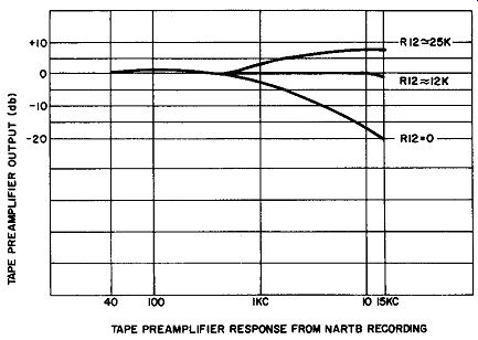
--------------- (B) Response curve.
Phono preamp.
STEREO HI-Fl PREAMP
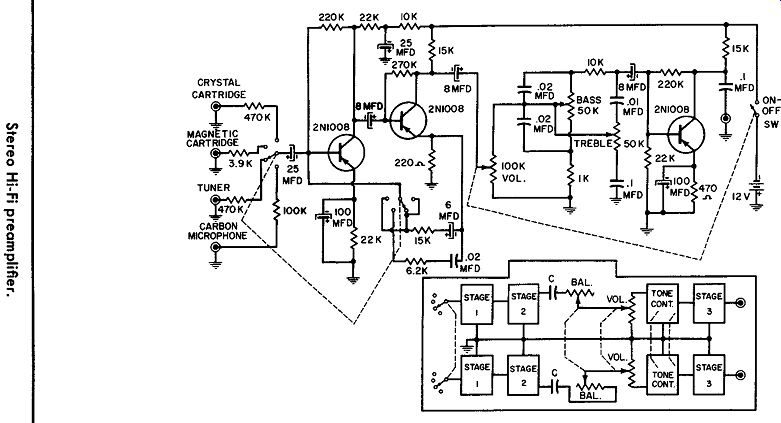
This three-stage transistorized preamplifier features four matched input impedances and volume, bass, and treble controls.
Stereo reproduction may be obtained with two similar units through the aid of a simple balance control, as shown in the block diagram. The input-selection, volume, and tone controls of the stereo amplifiers are ganged. The balance control is also ganged and connected as shown so that the amplifiers will operate in opposition to each other.
FIVE-TRANSISTOR PHONO AMPLIFIER
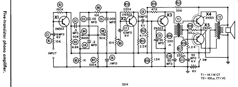
In this four-stage, five-transistor amplifier, the maximum out put power is 1.0 watt (0.75 watt at 10% distortion). Three RC coupled stages are used ahead of the push-pull output. All stages are 2N323's except those at the output, which are 2N321's with clip-on heat sinks.
R9, feeding the base of X2, is the 10K volume control. R4 is the 50K bass control, and RS is the 59K treble control.
--------------
-------------
THREE-TRANSISTOR PHONO AMPLIFIER
This is a two-stage, three-transistor amplifier suitable for use with phonographs. The input stage is a 2N192 or a 2N324 feeding a transformer with a center-tapped secondary. The resulting two phase signal drives a pair of 2N241A's in push-pull.
Maximum output power is 0.35 watt. However, with 10% harmonic distortion, the greatest power output is about 0.25 watt.
A crystal pickup is used in this circuit; and for a magnetic in put, R (220,000 ohms) is omitted from the circuit.
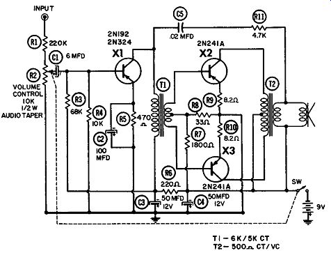
--------------- Three-transistor phono amplifier.
FOUR-TRANSISTOR PHONOGRAPH AMPLIFIER
This phonograph amplifier has a maximum power output of 0.75 watt and a distortion of 10% at 0.45 watt. RC coupling is used between the first two stages, while transformer coupling is employed to and from the push-pull output stage.
Provision is made for either a magnetic or crystal pickup. Signal voltage across the 5K control is applied to the base of the first stage to control the volume. The tone control provides the response curves shown.
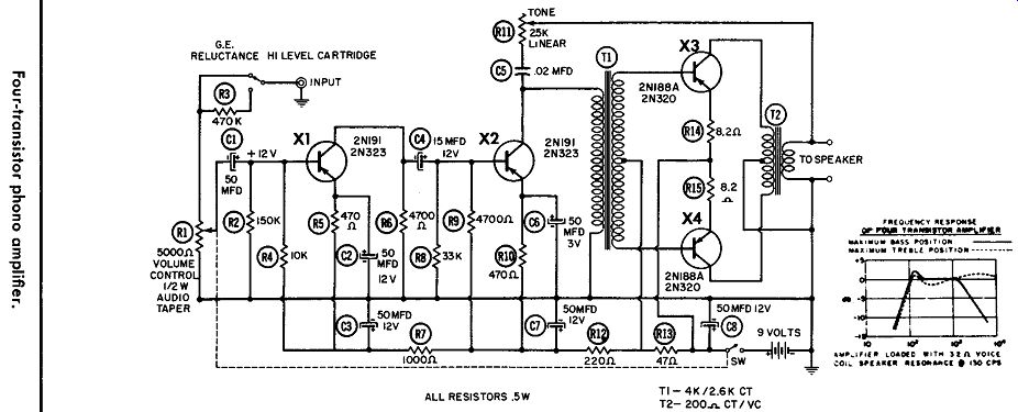
----------------
2-WATT PORTABLE AMPLIFIER
This is a four-transistor, three-stage portable amplifier for phonograph or radio use. The power transistors run at a very low power level and need not be mounted on a heat sink. The circuit is designed to give high output with long battery life, and the gain is more than adequate for most crystal pickups.
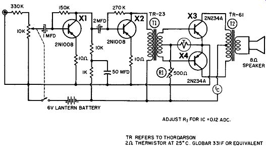
------------ 2-watt portable.

---------------
PORTABLE PHONOGRAPH AMPLIFIER
A lightweight portable record player having a 0.5-watt output may be constructed using this transistor amplifier. The turn table may be either a battery-powered electric or the older, man ual type. A simple electronic power supply may be substituted for the battery. Total current drain is about 514 ma.
Here, four RC-coupled stages are used. The circuit has been designed so that transistors having lower betas ( such as types 2N107, GT222, and CK722) may be substituted for the 2N180 units.
PORTABLE RADIO POWER AMPLIFIER
This amplifier is plugged into the speaker jack of a small portable transistor radio. The low power output and high impedance of the radio are coupled to the base of the Class-A amplifier ( 2N255) through impedance-matching transformer T1.
This circuit is capable of developing 1 watt of output power.
R1 controls the gain of the circuit by varying the forward bias of the emitter-base junction.
T1: 500·OHM TO 8·OHM TRANSISTOR TRANSFORMER ( ARGONNE AR-164)
T2: 48- OHM TO 3.2 OHM OUTPUT TRANSFORMER ( ARGONNE AR-503)
40-OHM THERMISTOR, VECO 14X2
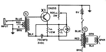
---------- Portable radio power amplifier.
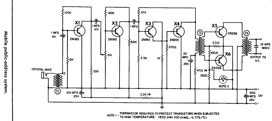
MOBILE PUBLIC-ADDRESS SYSTEM
This high-power amplifier is part of a mobile public-address system. It will operate directly from a 12-volt storage battery without a transformer or vibrator supply. The push-pull, Class B operated 2N256's will furnish 10 watts of audio power. This design shows a negative ground, for installation in an automobile.
Therefore, the circuit ground should be wired to the negative ground and bypassed with a large capacitor. Lower-gain transistors such as the 2N107, GT222, and CK722 may be substituted for the 2N180 units.
This amplifier is shown for use with a crystal microphone. If a dynamic mike is to be used, take out the input transformer and connect the mike to point 2.
---------------
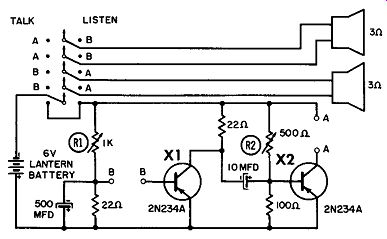
TRANSFORMERLESS INTERCOM
This is a low-transistor intercom using a single 6-volt source.
Because of the low internal resistance of power transistors, the transformerless intercom gives a very high gain and power out put even though directly coupled to the speaker.
It is necessary to adjust the bias with resistors R1 and R2 to supply 3 volts of collector-emitter voltage across each power transistor. However, once the bias is set, the resistors can be replaced with the nearest fixed carbon resistor. The Talk-Listen switch should be of the spring-return type to give a long battery life.
This intercom circuit is not critical, and a heat sink for the transistors is not necessary. The voice coil is driven directly by the transistors; therefore, no output transformer is needed.
------------- Transformerless intercom.
LOW-COST TRANSISTOR MEGAPHONE
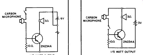
Two low-cost transistor megaphones are shown here. Both put out a surprisingly large amount of power, considering the simplicity of their circuitry. It is suggested that the battery and speaker be mounted in a cardboard box, with the microphone on a long wire away from the box to prevent feedback. A spring return push-to-talk switch should be used to save the battery.
Both circuits use the 2N234A transistor.
In Part A, the circuit produces about 0.33 watt. Six volts is supplied, arranged so there are +3 volts and -3 volts, whereas in Part B only one 3-volt supply is required. Both circuits have a 3-ohm voice coil in the collector circuit.
------------ (A) 6 VDC system. (B) 3 VDC system. Low-cost transistor megaphone.
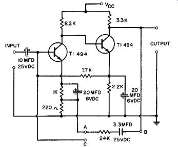
TWO-STAGE MULTIPURPOSE AMPLIFIER
A two-stage amplifier using TI-494 transistors is shown. Operating over a temperature range of -20° to +100°c., this circuit can provide a voltage gain of 40 db from a power source in the 10- to 25-volt DC range. The circuit is flat within 3 db from 10 cycles to 1 megacycle. This basic amplifier also may be utilized as a sensitive AC voltmeter, tuned amplifier, or tuned oscillator by simply employing different networks between terminals A and B or C and B. At 1,000 cycles, the input impedance is 20,000 ohms and the output impedance is less than 50 ohms. The maximum input is 80 millivolts rms.
----------- Two-stage multipurpose amplifier.
POWER MEGAPHONE
Here, two power megaphones are shown. In Part A of the dia gram a minimum number of parts are used to obtain a 1-watt output. Of the two circuits shown (A and B) the 1-watt output will be adequate for most applications. In Part B the 6-watt mega phone is quite powerful and should be considered a deluxe model.
Wiring and parts layout are not critical, and both amplifiers are designed for use with a conventional 6-volt lantern battery. How ever, the transistors in the 6-watt megaphone should be mounted on a heat sink.
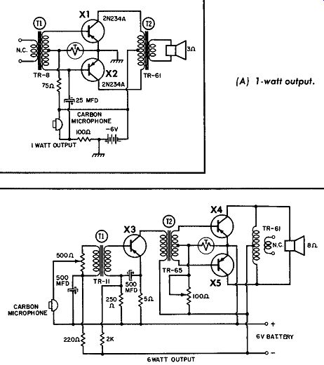
-------- Power megaphone. (A) 1-watt output. (B) 6-watt output.
Note in Part A that the output transformer is used with a 3-ohm voice coil, but that in Part B the 8-ohm voice coil is across the primary and no secondary is used.
AUDIO MODULATOR
For modulation, transistors offer much smaller circuits with less power drain than tubes. The transistorized modulator shown here is capable of supplying more than 25 watts of audio power at better than 50% efficiency. Output transformer T1 can be an ordinary 12-300-volt vibrator-type power transformer. It is necessary to mount transistors X1, X2, and X3 on the chassis for efficient heat dissipation. A mounting kit should be used for electrical isolation. The Thermistor readjusts the bias to prevent distortion when the chassis becomes warm. The circuit is de signed for use with either a crystal, dynamic, or carbon micro phone.
For a crystal mike, two stages of amplification are placed be fore driver X3 as shown. With a carbon microphone, the 14-volt supply is the voltage source through the 220-ohm resistance. The Thordarson 46 then replaces the 45 transformer, and the first two stages (X4 and X5) are not used.
MOBILE HIGH-LEVEL MODULATOR
This unit will supply 10 to 12 watts of audio-output power, which is sufficient to 100% modulate a 6V6 or 2E26 final RF amplifier. A carbon-mike input is used, along with a 2N180 amplifier, a 2N255 driver, and a pair of 2N256's in push-pull. This push-pull stage is the output to the RF stage through the modulation transformer. The microphone input transformer is not critical, and the output transformer can be the universal tube-to speaker type with several impedance taps. One tap is centered; e.g., with 4-, 8-, and 16-ohm taps, the 4-ohm tap is centered be tween the common and 16-ohm taps. The common tap connects to one collector, the 16-ohm tap to the other collector, and the 4 ohm tap to the power supply. The output impedance of the transistor is twice these values, so that the secondary impedance is double the marked values. Otherwise, the modulation transformer is designed for transistor modulators and connected as marked.
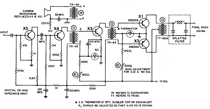
------------------ 2-ohm THERMISTOR AT 25°C GLOBLER 331F OR EQUIVALENT R1
SHOULD BE ADJUSTED SO THAT ICON X3 IS 300MA
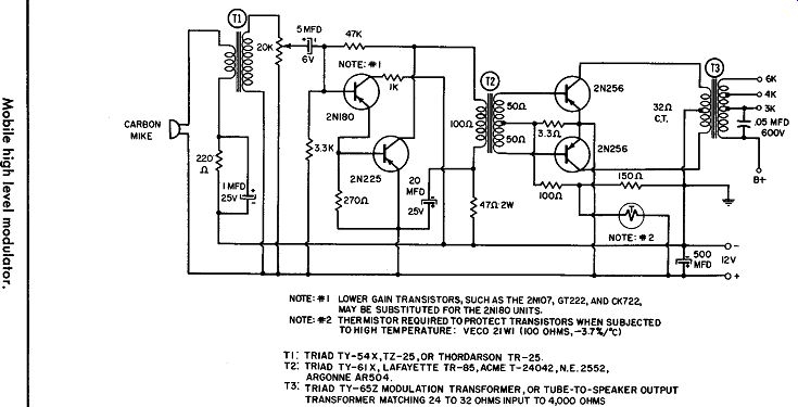
------------ LOWER GAIN TRANSISTORS, SUCH AS THE 2NI07, GT222, AND CK722,
MAY BE SUBSTITUTED FOR THE 2N180 UNITS.
NOTE: THERMISTOR REQUIRED TO PROTECT TRANSISTORS WHEN SUBJECTED TO HIGH TEMPERATURE: VECO 21WI 1100 OHMS,-3.7'1./"C)
T1: TRIAD TY-54X,TZ-25,0R THORDARSON TR-25.
T2: TRIAD TY-61 X, LAFAYETTE TR-85,ACME T-24042,N.E.2552, ARGONNE AR504.
T3: TRIAD TY-652 MODULATION TRANSFORMER,OR TUBE-TO-SPEAKER OUTPUT TRANSFORMER MATCHING 24 TO 32 OHMS INPUT TO 4,000 OHMS
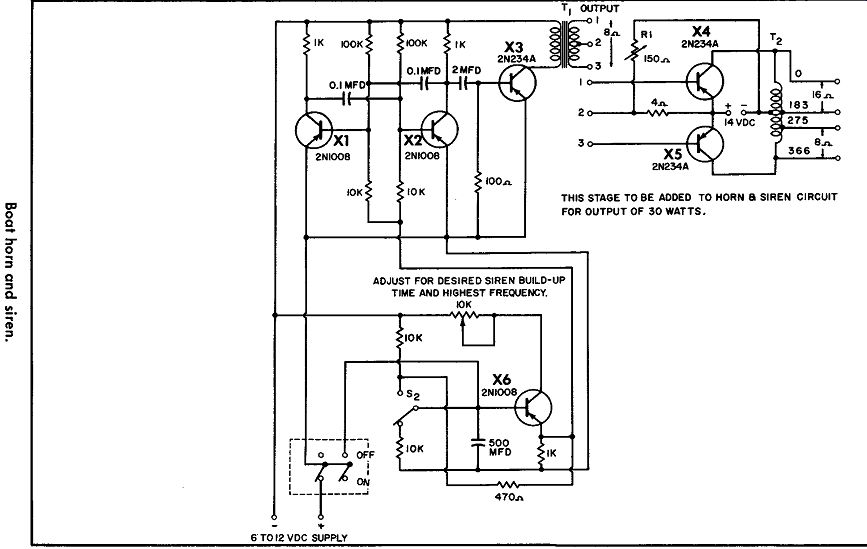
------------------ THIS STAGE TO BE ADDED TO HORN a SIREN CIRCUIT FOR
OUTPUT OF 30 WATTS.
BOAT HORN AND SIREN
This boat horn-and-siren circuit provides an output of 0.75 watt and, using the additional power-output push-pull stage shown, is capable of delivering 30 watts output.
The Off-On switch is used for the horn. When it is closed, X2 and X3 oscillate at a frequency determined by the 470-ohm resistor tied to the emitter of XL Output from the oscillator is amplified by X4, which feeds output transformer T1.
As a siren, first the Off-On switch is closed, and then S2. As the large capacitor in the X1 base circuit charges, the siren frequency rises. The 10K pot controls both the build-up and the highest frequency.