AMAZON multi-meters discounts AMAZON oscilloscope discounts
In a broad sense, almost all circuits in this guide provide some type of control-for example, they control voltage, current, frequency, or some other parameter. However, the circuits in this section are industrial controls, which transfer power from one place to another, adjust the temperature, etc.
One of these circuits switches on emergency power. The regular power from the line is furnished to the load through a switch, which remains off and thereby isolates the emergency power source. If the regular power source should fail, however, the emergency power source will be switched in automatically.
Another type of control is the servo drive, where an amplifier controls the rotation of a servo in one direction. Where a reversing drive is necessary, two amplifiers can be used, one for each direction. A balanced bridge input between the two amplifiers will provide an input signal to the correct amplifier, depending on the polarity of the error signal.
There are several ways of classifying automatic control systems.
One way is to define their action in terms of proportional, floating, or two-position. Two-position control provides fully on or off operation of the controlled device; there are no intermediate positions. Many applications such as a simple on-off motor control are best served by two-position arrangements.
In floating controls, the controlled device is moved as required to maintain conditions at the control set point. Floating control permits the system to stop at any position between fully on and fully off. However, its applications are limited because of its tendency to overshoot. Overshooting is likely to set up cycling ( also called "hunting") in the system. Both overshooting and hunting are the result of time lags in the over-all system.
In proportional control, the actuators assume a position proportional to the change in conditions. These conditions can be temperature, pressure, light, or almost any other controlled vari-able. For a given increment of change in the variable, the con trolled device will move to a position which is proportional to that increment. In this way, the floating control does not cycle, since the actuator always reaches the same position for any given load on the system. In proportional action, feedback links the actuator to the controlled device. As the actuator moves in response to a change in load, a signal is fed back. The effect of this feedback is opposite from the charge caused by the variation in load. When these opposite effects balance, the system stops moving, usually before it can reach the extreme open or closed position.
Electronic control systems can measure, detect, count, control, warn, and inspect-but to do any of these things, a sensor is required to produce the electrical signal. A transducer, which is mechanically or electrically coupled into an electronic circuit, can vary capacity, inductance, or resistance. This variation can change the current, voltage, or frequency by means of a wide variety of piezoelectric, photoelectric, or magnetic devices. With this system it is possible to measure pressure, temperature, humidity, or other variables.
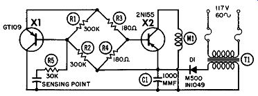
------------ Transistor detection sensor.
TRANSISTOR DETECTION SENSOR
This transistorized control uses currents as low as 50 micro-amps to prevent arcing at the points of sensing or switching contacts Two stages of transistor amplification permit operation of a standard 5-amp control relay. The control is designed for operating temperatures from 0° to 50°C. Its dimensions are 10" x 5" x 4", and it weighs six pounds. The control can use one, two, four, six, or eight probes in series, all of which must be contacted to complete the circuit.
A transistorized control utilizes extremely small currents to provide spark-free switching, detecting, locating, and counting.
The electronic sensing device operates with currents in the 50-150-microamp range and with voltages between 6 and 7 volts DC. Two stages of transistor amplification permit operation of a standard 5-amp control relay.
Small, lightweight metal parts can be detected merely by touching them with a sensitive point or probe. The metal part then acts as a resistor in the bridge arrangement used to bias the transistors. Unbalancing the bridge by addition of this external resistance causes current to flow through the first transistor stage. This current triggers the second transistor. A relay in the collector circuit of the second stage is then energized to control subsequent operations.
The low voltage and current present at the sensing point will allow the sensitive contacts to be only 0.0001 inch apart without actuating the relay. A maximum of 20K ohms is required for sufficient unbalance to actuate the relay. Yet, an instantaneous signal is given on contact; no pressure or depression is needed.
The unit can detect up to 1,500 actuations or contacts per minute, no matter how light or small. A ¼-inch probe can be placed in a die to check for proper placement of the blank.
Precise location of a part or member is possible because of the .0001-inch "no-circuit" feature.
AC from the secondary is rectified and filtered through D1 and C1. X1 and X2 are biased through a bridge made up of R1, R2, R3, and R4. As long as sensing points are open, no current flows through R1. The instant a direct short or external resistance ( 20K maximum) is felt at the sensing point, the bridge is un balanced and X1 conducts. Current flow through X1 causes a drop across R3 and R4, and also changes the bias on X2. When X2 conducts, current flows through Ml ( which has one pair of normally open or normally closed contacts). Control leads to the sensing probes can be of any length. Thus, the control unit can be placed at a distance from the sensing point.
SCR PROPORTIONAL CONTROL
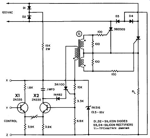
When used with AC load power, the controlled switch (CS) or silicon-controlled rectifier ( SCR) will block and will not con duct during both half-cycles unless a gate signal is supplied. The CS or SCR can be turned on at any point during the positive half-cycle, as long as the anode is more than +3 volts with respect to the cathode. By proper timing of a gate signal, the out put of the CS or SCR can be made continuously variable from no output to full output, as shown.
Since the internal dissipation of the CS or SCR is very low, the loss of the proportioning power control is also very low. The low-power requirements for gate firing permit the design of simple proportional-control amplifiers with very high gain.
--------------- SCR proportional control.
A proportioning-control amplifier with full-wave rectified DC output is shown here. The DC input voltage, which is variable from 4.9 to 5.1 volts, will provide full output control. This circuit is useful for servomotor driving, temperature control, and related applications. Closed-loop feedback is easily achieved for self-regulating systems.
The power-control circuit becomes a regulated DC power supply when part of the DC output voltage is applied to control input Y. Since the control reference is approximately five volts, a voltage divider across the load will regulate the DC output voltage to 5 volts multiplied by the divider ratio. If the load voltage is unfiltered, a small capacitor may be required across the control input.
Regulated DC power supplies using the SCR eliminate the need for high-dissipation series control elements such as power transistors or tubes. This greatly minimizes heat-sink requirements and permits smaller packaging. In addition, the supplies provide a wide control range. A possible disadvantage is their response time, which can be no faster than one half-cycle of the supply voltage.
A bridge circuit can be formed by connecting a resistor from X to Y and from Y to Zin the control circuit. Together with the resistor network connected to the base of X2, this bridge forms the basis for many simple and reliable power-control circuits.
This it does by using a variable-resistance transducer as one of the two resistance elements at the input. Examples include resistance thermometers for temperature control, and photoconductive cells for light control.
RELAY DRIVER
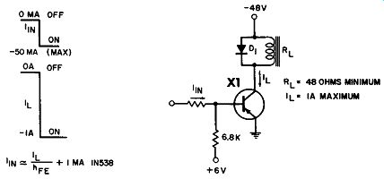
In many industrial controls, a transistor is needed to drive a relay which, in turn, can control a power circuit. The figure shows a 2Nl039 in such an application. A potential of +6 volts is applied to the base, and -48 volts to the collector.
A 50-mil current at the input turns the transistor on and causes a 1-ampere current How through the relay. The resistance of this coil should be at least 48 ohms. When the input and relay cur rents stop, the 1N538 diode will clip the reverse-voltage swing.
As the arm of R1 is moved to the left, X1 and its associated SCR's begin to fire. At the extreme left-hand position of R1, the full output voltage appears across the load. As the arm of R1 is moved to the right of center, a similar action occurs except the polarity across the load is reversed.
------------------ Relay driver.
If the load is a DC motor, a plugging action occurs if R1 is reversed too abruptly. R14 and R15, in series with each end of the transformer, limit the fault current in event a voltage transient fires an odd- or even-numbered SCR pair simultaneously.
RELAY CIRCUIT
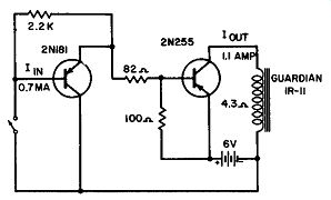
This sensitive relay circuit has a high-temperature stability, and an input current of less than LO ma will control a LO-ampere solenoid. It is useful in model boats and airplanes, as well as in other remote-control devices. If the amplifier is not to be subjected to temperature extremes, a 2N107 may be substituted.
---------------- Relay circuit.
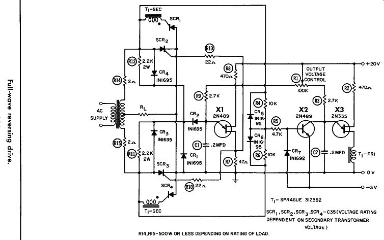
---------------- R14, R15-500 W OR LESS DEPENDING ON RATING OF LOAD.
FULL-WAVE REVERSING DRIVE
This full-wave circuit controls and reverses a servo, as shown in the diagram. Two SCR's (2 and 3) have a common-cathode connection, and the other pair ( 1 and 4) have a common anode.
SCR-2 and SCR-3 are fired by unijunction transistor XL Since SCR-1 and SCR-4 have electrically isolated cathodes, the gate signal pulse generated by UJT X3 is coupled to the SCR gates by isolated secondary windings on transformer TL Transistor clamp X2 synchronizes the firing of X3 to the anode voltages across SCR-1 and SCR-4.
R1 can be made to regulate the polarity as well as magnitude of the output voltage across the load. With R1 at its center position, neither UJT will fire. Hence, no output voltage will appear across the load.
MAGNETIC-AMPLIFIER CIRCUIT FOR AN SCR
There are several magnetic amplifiers for SCR control, as shown by the schematic in Part A of the diagram. This control amplifier is symmetrical, one half firing a controlled rectifier on one half-cycle of an AC excitation while the other half fires a controlled rectifier on the other half-cycle. Part B shows only one half of this symmetrical circuit working into a controlled rectifier.
The object of the circuit is to be able to gate ( turn on) the SCR at any desired firing angle in the forward-conduction half cycle of the SCR, and thus to control the power to the load. The SCR will be turned on when the required current is put into its gate. A sharp current signal is generated when the magnetic amplifier winding ( Ncl) saturates. The time at which it does during the cycle is determined by the ampere-turns of DC control applied to the amplifier.
The purpose of T1 is to bypass the current of the magnetic amplifier around the gate. The increase in magnetizing current, when the amplifier is driven with large negative signals, does not fire the controlled rectifier.
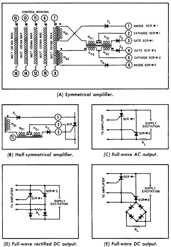
---------------------- Magnetic amplifier for an SCR. (A) Symmetrical amplifier.
(B) Half-symmetrical amplifier. (C) Full-wave AC output. (D) Full-wave rectified
DC output. (E) Full-wave DC output.
Magnetizing current through reactor gate winding Ncl is passed directly through winding NP on the transformer. Since its magnetizing current is more than that of Ncl, the transformer cannot change flux. Once the reactor saturates, the high gate impedance no longer restricts the gate current and it rises rapidly.
When this increased current equals the magnetizing current of the transformer, the transformer changes flux ( saturation-to saturation). A voltage is induced in secondary Ns as the flux changes, and the resultant current pulse gates the SCR. On the next half-cycle, the other half of the symmetrical circuit goes through a similar cycle. Because the transformer is polarized when the reactor of that half of the circuit saturates, the transformer must again change flux level. This means it is at the proper saturation level at the beginning of any half-cycle, and will have to go through a complete flux change if NG saturates at any time during that half-cycle. Diodes X2 and X4, as in Part A, are in series with each of the gates to block reverse currents.
The output of a control amplifier is a narrow pulse, the firing angle of which is varied by the net DC control ampere-turns. The height and width of this pulse vary with, and are determined by, the gate requirements.
Three typical circuits show the control amplifier and associated controlled rectifiers. These are only representative; many other circuit configurations are possible. The ones in C and E are particularly advantageous, since the two controlled rectifiers are in parallel-the two conduction directions being opposite each other.
In the presence of an overvoltage, the controlled rectifier which would conduct because of this polarity voltage will break down.
Normally this will occur before the rectifier with a reverse voltage across it breaks down in the reverse direction. In this manner, the controlled rectifiers in these circuits protect each other against inverse voltage breakdown. The surge-current rating of the con trolled rectifiers determines the maximum overvoltage that will damage the controlled rectifiers.
SCR MOTOR CONTROL
Controlled rectifiers can provide a simple, accurate speed control for a DC motor. AC is in series with the motor and con trolled rectifier TCR-2005. This circuit gives smooth control of motor power over the complete control range. During the negative half-cycle, the 10-mfd capacitor will charge to a negative voltage through the 5K potentiometer. During the positive half cycle, the capacitor will charge to a positive voltage through diode TK20 and part of the potentiometer. When the voltage at the capacitor becomes positive, diode TK5 will start to conduct and the CR will fire. The greater the resistance shorted out on the potentiometer by diode TK20, the faster the capacitor will re charge, the greater the conduction angle of the CR will be, and the greater the current that will flow through the motor. There fore, the 5K control is the adjustment for the motor speed.
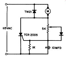
--------------- SCR motor control.
SERVO DRIVE
A servo amplifier controls the rotation of a motor. Where a reversing drive is necessary, two amplifiers can be used, one for each direction. A balanced bridge input between the two amplifiers will provide an input signal to the correct amplifier, de pending on the polarity of the error signal.
For simple AC systems, the output circuit shown could be used. It provides a constant-amplitude AC sine-wave output with reversible phase. It is therefore a reversing drive for AC motors. The load voltage will either be in phase or 180° out of phase with the supply voltage, depending on whether the control AC input is in phase or 180° out of phase with the supply.
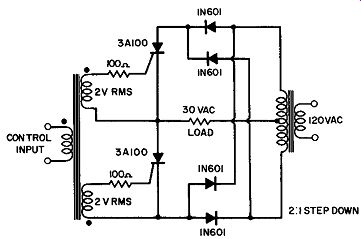
------------ Servo drive.
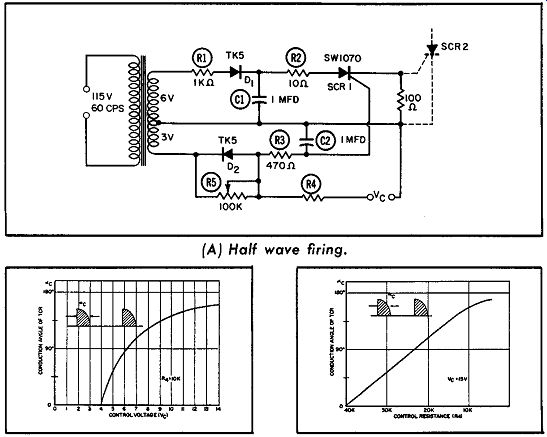
----------- Half-wave SCR circuit. (A) Half wave firing. (B)Control voltage vs
(C)Control resistance vs conduction angle. conduction angle.
HALF-WAVE SCR CIRCUIT
The circuit in Part A shows the half-wave control of the firing of a controlled rectifier. Line voltage is applied through the transformer. During one half-wave, the TCR will not fire. This period is used to charge C1 ( via D1) to approximately +8.5 volts, and C2 ( via D2) to approximately -4.2 volts.
The control current, caused by control voltage Ve through R4, recharges C2 until the voltage over it reaches the V GT of the controlled switch. This switch is triggered, and the charge stored in C1 can now How ( via a low-impedance path) into the gate of the CR. The control range is from 0° to 160°. The conduction angle of the TCR is determined by the control current and by the voltage to which C2 is charged during the negative half-wave.
Compensation for line-voltage variations is provided. The conduction angle of the CR has an inverse relationship to the input line voltage. The degree of compensation can be controlled by R5.
Part B shows how the control voltage varies between 4 and 14 volts, and its effect on the conduction angle. This angle is always less than 180°. Part C shows how the conduction angle varies with the control resistance, while the control voltage is fixed at 15 volts.
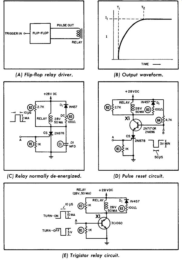
---------- Relay control. (A) Flip-flop relay driver. (C) Relay normally de-energized.
(B)Output waveform. (D) Pulse reset circuit. (E) Trigistor relay circuit.
RELAY CONTROL
Relays cannot be driven directly by short trigger pulses. In stead, their pulse-width or current-flow time must be long enough to energize them. Suppose, as in A, that a certain relay requires 11 amperes before the relay will close and activate the following control circuit. If this current flow starts at time T1, it will not build up to 11 until time T2, because of the normal lag in current flow in an inductance. One way to use a short-duration, low-level pulse to close a relay is to have this pulse switch a flip-flop, as in B. The flip-flop's output-which is a longer-duration, higher-level pulse than that of the input trigger-then drives the relay. An out put current flows from T1 to at least T2.
Semiconductor switches can do the same job with fewer components, as shown in C. The relay in C is normally off ( not energized). When a trigger pulse is applied, the controlled switch is triggered on. Resistor R2 allows the current through the CS to rise above its holding level while the command pulse is present.
When the command pulse terminates, the CS remains on and full voltage is across the relay. The time required for the relay to energize is not important from a circuit viewpoint. This circuit is reset by momentarily interrupting the anode current of the CS. One method of accomplishing pulse reset is shown in D, where an NPN transistor is placed in series with the CS; resistor R4 provides a saturating base drive to the transistor. To reset the circuit, a negative pulse is applied to point B. This pulse momentarily interrupts the anode current of the CS, which turns off. CS will then remain off until a turn-on command pulse again appears at the input.
The circuit in E uses a silicon Trigistor as the active control element. Since the Trigistor can be turned off as well as on at its base terminal, it can perform the same function as the circuit in D but with fewer components. Command pulses for both turn on and turn-off are applied at the same point, as shown. Turn off time can be much shorter with the Trigistor.
The relays require a coil current of 50 ma. The circuits can be easily adapted to control relays, solenoids, or other loads requiring from 5 to 1,000 ma. In addition, by proper choice of CS or Trigistor, pulse widths as narrow as one microsecond can be used as command signals. Many variations are possible, and almost any desired type of pulse control can be achieved.
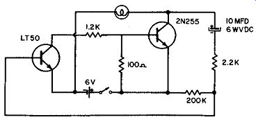
-------------- Complementary multivibrator.
COMPLEMENTARY MULTIVIBRATOR
A complementary transistor multivibrator using a 2N255 and an LT-50 is shown here. The application is in a battery-operated barricade flasher. The desirable feature of this circuit is that both transistors conduct at the same time, whereas in conventional multivibrators they conduct alternately. The complementary transistor circuit therefore consumes less power.
A 6-volt DC source is used, with 16 mils in the "off" position for both transistors, and 460 mils in the "on" position. The period of operation is 2.4 seconds, as shown, with a duty cycle of 16.6 % .
POWER TRANSFER
This circuit switches on emergency power in the following manner. As the regular power source is functioning, power is furnished to the load through the four-layer diode 4D1, which remains off and thereby isolates the emergency power source from the load. If the regular power source fails, the full voltage of the emergency power source will be impressed across 4D 1 and turn it on. The switching voltage of 4D1 is selected so that nor mal variations in the voltage of either the regular or emergency power source will not switch 4D1.
D1 is back-biased, isolating the regular power source from the load, and power is fed to the load from the emergency power source through D2 and 4D1. Normal load current keeps 4D1 conducting until the emergency power source is interrupted. As soon as the regular power source is restored, it will take over from the emergency source ( provided its voltage is higher than that of the emergency source). D2 prevents reverse breakdown of 4D1 when the emergency power source is not energized. Four layer diodes have a typical switching time of 0.1 microsecond.

------------- Power transfer. (A) Typical inductive circuit (unsuppressed).
(B) Circuit interruption generating high reverse voltage. (C) Selenium rectifier
shunts coil. (D) Arc suppressor across coil. (E) Suppressed circuit waveform.
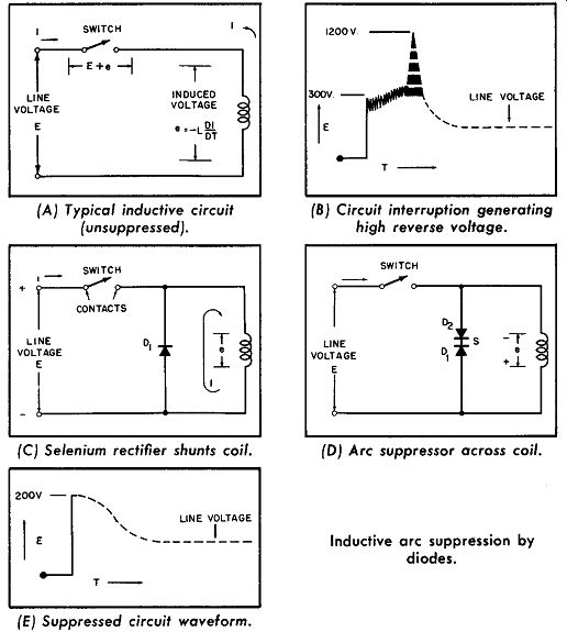
--------- Inductive arc suppression by diodes.
INDUCTIVE ARC SUPPRESSION BY DIODES
Several techniques for arc suppression are shown. Every inductive circuit controlled by switches, relays, or other types of make-or-break devices will, when interrupted, generate high voltage transients which will cause arcing across the contact points. If the load is inductive, arcing will damage the contacts and ultimately cause them to lock. In addition, the voltage transients are of an RF frequency and therefore a source of interference to any adjacent circuits. They are also of sufficient magnitude to puncture the insulation.
The problem is particularly acute in modern circuits, where certain critical components are operated at their maximum ratings. In such instances, the voltage overload will seriously impair the efficiency of these components-if not break them down completely.
Part A of the diagram shows how, with a line voltage E, an inductive voltage e is created by a decline of the magnetic field when the switch is opened. Arcing starts here at 300 volts, as shown in Part B. Part C shows a half-wave rectifier connected across the coil in a DC circuit. The low forward impedance of the rectifier shunts the coil and prevents the reversed voltage ( generated by circuit interruption) from attaining arcing potential. Current decay time, however, is prolonged because the low forward impedance of the rectifier allows the current to circulate longer than in an unprotected circuit.
Part D shows an arc suppressor consisting of selenium-rectifier cells connected back to back across the coil. This type of suppressor is efficient for DC but essential for AC, since the suppressor must block both voltage polarities. Back-to-back suppression effectively dissipates the induced energy, but does not materially slow down the current decay, as shown in E. With the switch closed, the A cells act as blocking rectifiers and the circuit performs normally. When the switch is opened, the resistance of the A cells is negligible, while the resistance of the B cells decreases as the voltage increases, preventing the back emf from reaching arcing potentials. The current that is allowed to flow, quickly dissipates the induced energy and causes the induced voltage across the coil to fall, thereby effectively dampening any further current circulation. A and B cells interchange their functions when their polarities are reversed.
ALARM CIRCUIT WITH FLASHING MASTER LIGHT
This circuit provides an alarm system with a flashing master light. It may be used with the two most common types of alarm contacts, high power and signal power, as shown by Types 1 and 2. A system can be composed of all Type 1, all Type 2, or a combination of both.
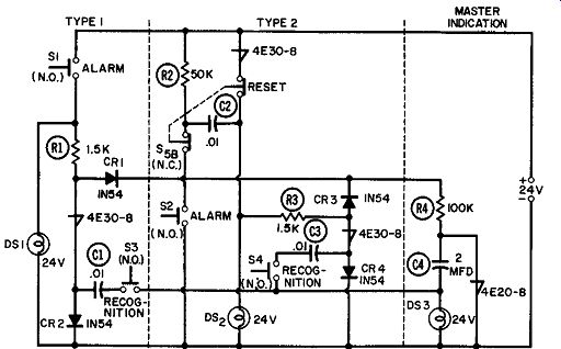
------------- Alarm circuit with flashing master light.
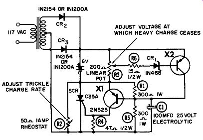
-------------- Battery charger regulator.
Type 1 is used when the alarm contact closes positively. It is capable of passing the required current, and must be reasonably close to the alarm panel ( unless shielded wire can be used ) . In Type 1, when an alarm occurs, S1 closes and signal lamp DS1 goes on. In addition, master light DS3 begins to flash. When the fault is recognized, recognition switch S3 is momentarily closed to turn off the master lamp. As soon as the alarm condition has been removed, S1 will open and signal lamp DS1 will go out.
In Type 2 the circuit operation is the same but each alarm point is independent of the others. If an alarm condition exists at S1 and has been recognized but not corrected, DS1 will remain on. If, during this time, an alarm occurs at S2, master lamp DS3 will flash until the second alarm, at S2, is recognized.
BATTERY-CHARGER REGULATOR
This figure, with two 2N525 transistors and an SCR, shows an inexpensive means of utilizing the SCR as a battery-charger regulator. Thus, the problems inherent in electromechanical voltage relays-sticking, contact burning, wide range of pickup and dropout, wear, etc.--are eliminated. As shown, this circuit is capable of charging at a rate of up to 16 amperes. When the battery voltage reaches the full-charge level set by R3, the SCR cuts off and a trickle charge ( determined by the value of R2) continues to flow.
A full-wave rectifier, comprising CR2 and CR3, delivers full wave rectified DC to the SCR in series with the battery. Transistor X2 compares a portion of the battery emf with reference diode C R1. If the battery voltage is low, X2 will be cut off. A positive voltage will be developed across resistor R1 and between the emitter and base of transistor X1 whenever the SCR anode is positive. X1 will conduct heavily into the gate of the SCR, firing it and thus charging the battery.
When the battery voltage rises to the point where X2 starts to conduct, the voltage across R1 will reverse, cutting off X1 and thus removing the gate signal from the SCR. In this mode, only resistor R2 will control the charging rate. This circuit switches from trickle to full charge with less than a 3 % drop in battery voltage.