You must locate what section the defective component is in before you can remove and replace it. With several different symptoms, you can isolate the trouble to a given section of the TV, radio, VCR, or CD player. After determining where the trouble is, locate the suspected part.
Remember, you don’t have a schematic diagram to locate the suspected component with accurate voltage measurements. Take voltage, resistance, scope, continuity, and semiconductor tests to determine if a part is defective (FIG. 1).
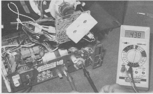
FIG. 1 Taking voltage and resistance measurements in the RCA TV chassis.
Correct test instruments
Today the most useful test instrument on the service bench is the digital multi- meter (DMM). This meter will accurately check the small voltage, resistance, continuity, and current required in solid-state circuits ( FIG. 2). Some DMMs will also test capacitors, transistors, and inductance. The DMM comes as pocket, portable, or expensive desktop test instruments. Purchase a DMM, even if you own a volt-ohm-meter (VOM).
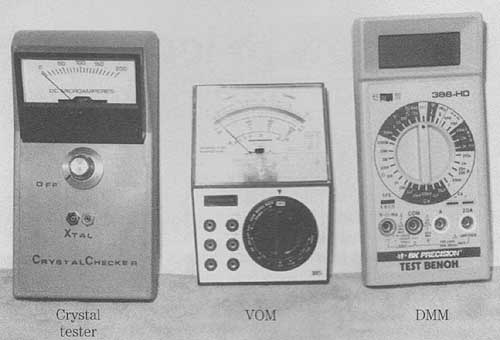
FIG. 2 The pocket DMM can take critical voltage, resistance, and current
measurements.
The oscilloscope is the next most used instrument found on the service bench. You can easily locate a defective component with critical waveforms in many different consumer electronic products. A dual-trace oscilloscope is needed with at least a 35- or 40-MHz frequency bandwidth (higher in some cases). Knowing how to use the scope will save a lot of time on the service bench. Don’t let the scope sit idle; use it. Besides regular hand tools, special and additional test equipment is listed in each section.
The following test equipment is needed:
• DMM
• Oscilloscope
• Transistor-semiconductor tester
• Audio signal generator
• Sweep generator
• RF signal generator
• The frequency counter
• Capacitance meter
• Color pattern generator
• Isolation transformer ( FIG. 3)
High failure rate of cheaply-made capacitors, often used i modern Chinese-made electronics, require diagnostic tools like this ESR meter:
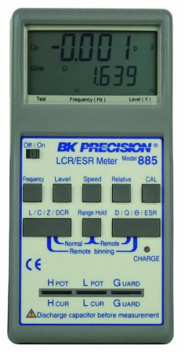
B&K
Precision 885 Synthesized In-Circuit LCR/ESR Meter with SMD Probe, 10kHz
Max Test Frequency
High accuracy LCR/ESR meters were the first handheld meters of their type on the market, offering fast, reliable, and versatile testing at a low cost. With a wide range of test frequencies up to 10 kHz, these LCR meters can perform many different measurements - Z, L, C, DCR, ESR, D, Q, and diameter. These instruments are designed for both component evaluation on the production line and fundamental impedance testing for benchtop applications. With a built-in direct test fixture, you can test lead components very easily. The optional 4-wire test clip can give a convenient connection to larger components and assemblies with the accuracy of 4-wire testing. Measurement parameters: Z, L, C, DCR, ESR, D, Q, and Diameter. 0.2 percent basic accuracy. Dual LCD display. SMD Surface Mount Tweezer Probe included. Very quick response, user friendly. Fully auto/manual selection. DC resistance measurement. Rechargeable battery / AC powered. Frequency accuracy: +/-0.1 percent. Level: 1Vrms, 0.25Vrms, 0.05Vrms, 1Vdc (for DCR). Level accuracy: +/-5 percent. Output impedance: 100 ohm, +/-5 percent. Operating temperature: 32 to 104 degree F (0 to 40 degree C). Storage temperature: -4 to 158 degree F (-20 to 70 degree C). Relative humidity: up to 85 percent. Battery type: Ni-MH or Alkaline (2 x AA size). Battery charge: Constant current 150mA approximately. Battery operating life: 2.5 hours typical. AC operation: 110V/220V AC, 60/50Hz with proper adapter. Low power warning: under 2.2V. Measures 6-57/64" length by 3-25/64" width by 1-57/64" height. 2 year warranty.
You must know how the unit is acting up before troubleshooting the chassis. For example, a dead TV might be caused by an open fuse, the low-voltage power supply, or the horizontal output circuits. A white line on the raster of a portable TV indicates a problem of insufficient sweep in the vertical section. Sides pulled in on the raster might indicate a defective low-voltage power supply, horizontal sweep, or pincushion circuits ( FIG. 4).
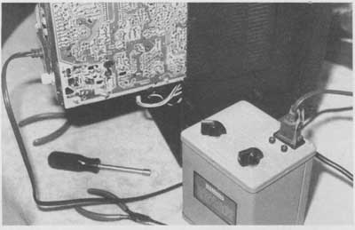
FIG. 3 Today, the isolation transformer should be used when you service
all electronic products.
What’s the symptom?
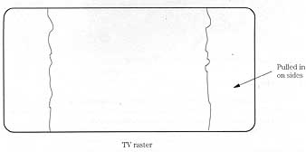
FIG. 4 The pulled-in raster of a TV can be caused by defective components
in the low-voltage source. TV raster; Pulled in on sides
A dead symptom in stereo radio circuits might indicate a defective low-voltage power supply to the audio output transistor, IC, or speaker. Excessive hum within a large stereo amplifier might be caused by defective filter capacitors. Pickup hum might point to worn input cables or circuits. No rotation of the disc in a CD player might be caused by a bad spindle motor or drive circuits. Use all the symptoms to locate the defective section within the electronic product.
Case histories:
Case histories should be looked at after determining what section the symptoms point to. Keep all cases in a card file, on computer, or right on the schematic. remember, the case history of one unit might help to solve problems in other chassis. Don’t forget to write down and record all tough-dog case histories ( FIG. 5).
Isolation:
Defective parts can be isolated as burned or damaged components ( FIG. 6). Overheated parts can be isolated by touch—the too hot or extra warm components. Touching the chassis and parts can indicate the intermittent component.
Alter isolating the possible defective section, isolate the defective part with transistor, IC, resistance, scope, and continuity tests. Test the transistors in or out of the circuit with a transistor-diode test using a DMM or a beta transistor tester. Check all suspected ICs with signal in and out, voltage, and resistance measurements. Before you can pinpoint the defective part you must locate it on the chassis without a schematic.
Locating components on the PC board:
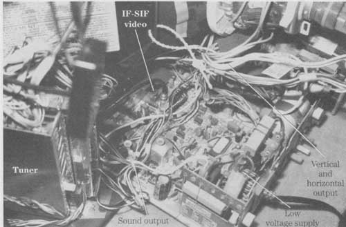
After isolating the various symptoms, find the correct section that the trouble might occur in. Look for large components, such as large filter capacitors for the low- voltage power source, transistors mounted on separate heat sinks inside the chassis for vertical output transistors or ICs, and the horizontal output transistors on separate heat sinks or metal chassis for the horizontal output circuits ( FIG. 7).
Another method for determining if you are in the correct section is to take the numbers located on the transistors and IC components and look them up in a semi conductor replacement manual. The manual tells you what pin goes where and what circuit it ties into on the chassis.
Look at the outline drawing for the correct pin connections. For example, the part number AN5435 lists as a color deflection signal processor in the RCA series replacement manual. The universal replacement is an SK9299 IC with pin 15 as the supply voltage pin (Vcc.). The horizontal drive output is pin 6, and the vertical output is pin 9. Also, the SK9299 has a total of 18 pins ( FIG. 8). Double-check with the IC mounted on the chassis for the correct number of pins, the right section, and correct universal replacement.
You might want to double-check the PC board wiring from each pin to where the parts tie into the troublesome circuit. Simply trace the wiring on the connected PC board wiring. Although this might take extra time, you might save tying up a TV chassis or cassette player for a long time until the schematic is available.
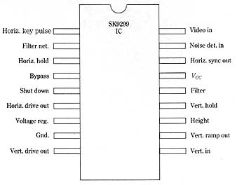
FIG. 8 The outline and pin drawings of an RCA SK9299 deflection signal
replacement IC (AN5345)
===
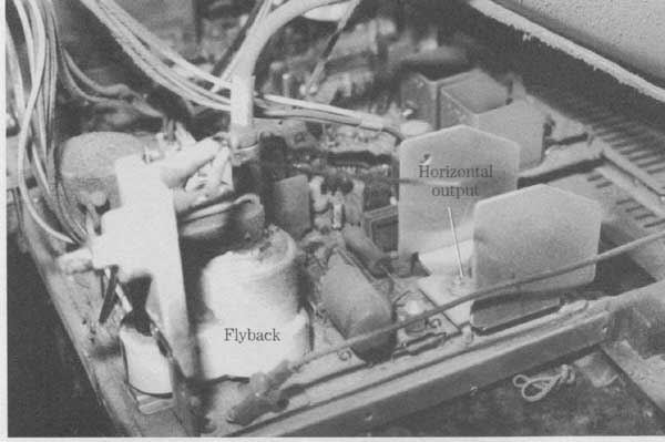
FIG. 7 Isolate the flyback and horizontal output transistor upon the TV
chassis.
SK9299 IC
Horiz. key pulse
Filter net
Horiz. hold
Bypass
Shutdown
Horiz. drive out
Voltage reg.
Gnd.
Vert. drive out I
______
Video in
Noise det. in
Horiz. sync out
Vcc
Filter
Vert. hold
Height
Vert. ramp out
Vert. in
===
Let’s say you have a Panasonic portable TV come in without a model number. The model number has been torn off, but it looks like a fairly new set, one that you have never worked On before. The symptom is a tic-tic sound with B+ present at the horizontal output transistor and no high voltage.
By supplying a horizontal pulse at the horizontal driver, you make the set run, indicating that the horizontal output stages, high voltage, and flyback circuits are normal. You think the AN5435 IC is the horizontal/vertical countdown IC. However, what pin is the voltage source (Vcc)? You look it up in the semiconductor replacement manual.
The AN5435 IC is a color TV deflection signal processor and can be replaced with an RCA SK9299 IC. Now you have located the correct IC and section that the trouble is in. Before replacing the IC, take voltage measurements on all the IC pins. Usually the highest voltage is the supply pin (Vcc). Supply voltage to the deflection IC is usually from 10 to 25 V. In this case, all pins are low in voltage. So you check the highest voltage pin and trace it back to the low-voltage source. If the low-voltage source is supplied through the flyback derived secondary sources, you are out of luck. Look up the supply voltage pin on the outline drawing of the replacement SK9299 IC. Pin 6 ties to the supply voltage source.
Inject an external 10 or 12 V at pin 6 with the scope probe on the horizontal driver (pin 15). If the horizontal waveform is normal, the IC is good. Double-check the vertical output drive waveform at pin 9. If there is no waveform at either pin, suspect a defective IC or leaky components tied to the IC pins and common ground. Replace the IC with a universal replacement if the original part number is not available. Sometimes the IC’s voltages and resistance measurements are normal but there are still no waveforms. Replace the IC at once.
Check the voltage at pin 6. Low or no voltage can indicate a leaky IC, improper supply voltage, or no voltage from the flyback secondary source. Trace the PC board wiring back to the supply source to locate a defective isolation resistor, silicon diode, or small electrolytic capacitor. By simply checking the number on the IC or transistor, you can determine what section the trouble is in, the correct pin, and the total number of pins.
Defective parts off the PC board:
Don’t overlook defective components that are not on the main chassis. Look for defective transformers, power transistors, voltage regulators, ICs, capacitors, and separate metal heat sinks or chassis. Check for problems in circuits on separate PC boards that are soldered to the main PC board ( FIG. 9). Suspect poor soldered connections from the horizontal PC board to the main chassis.
Burned or damaged components:
Burned or damaged parts are easily seen on the PC board. You might have to blow off dust to see the burned components. Sometimes you can smell burned or charred parts. The PC board might have to be repaired if it has been burned and damaged.
Large parts—such as transformers, electrolytic capacitors, and power output transistors—can easily be seen. Check for a part number on the body. It’s difficult to determine the total resistance in charred resistors. If the color code cannot be seen, try to locate a schematic similar to the chassis on the bench.
In many cases, the resistance might be close in value for several different known chassis in the same circuit. For example, two charred boost-dropping voltage resistors were found in a Sony portable TV chassis. Because the correct schematic was not available, another Sony portable (KV-1i47 circuit was used that was quite similar. There was no doubt that R720 and R715 were damaged when the picture tube arced over with excessively high voltage ( FIG. 10). Make sure the circuits are similar with the correct operating voltage.
Hot ground:
A common point known as a hot ground is a live circuit or above the common ground. The common ground in any electronic circuit can be referred to as a cold ground. All circuits are common to regular ground except the hot ground. When voltage or resistance measurements are made from a transistor or IC with a hot ground circuit to regular ground, these measurements are incorrect and misleading.
Many circuits of the switched mode power supply (SMPS) have a common hot ground. Look for a hot ground in switching power supplies. The ac input circuits are above ground or contain a hot ground. You will find hot grounds in the RCA, Sylvania, Goldstar, and several other TV chassis.
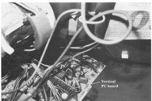
FIG. 9 Check the vertical board for possible broken PC wiring connections.
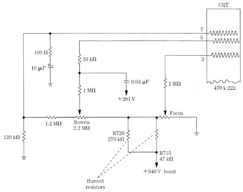
FIG. 10 Burned resistors can be located by checking a similar schematic
of the same brand.
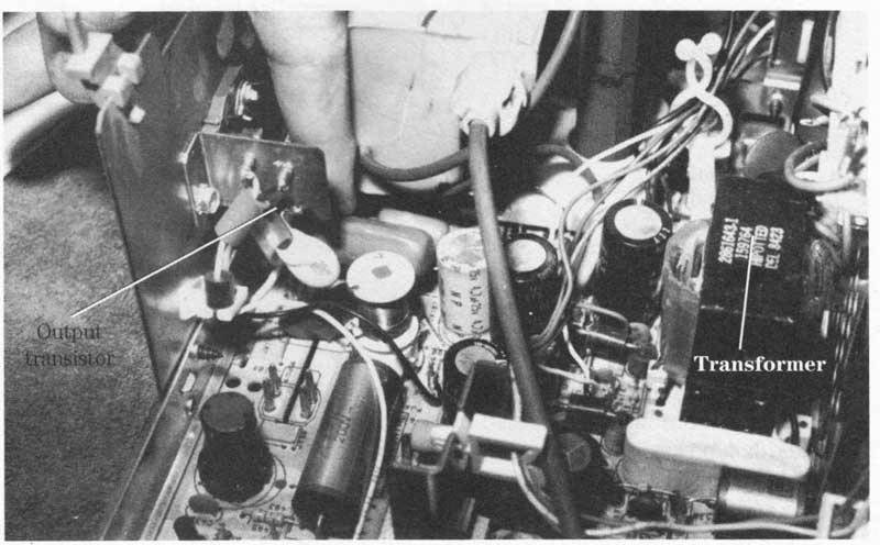
FIG. 11 The finger points at a hot ground transistor and transformer in
an RCA TV chassis.
Look for a switching or SMPS transformer found in the power supply circuit, which might indicate a circuit with a hot ground. Most schematics will show a hot ground with a triangle instead of the ground symbol. When servicing a chassis with out a schematic, check for a separate transformer and switching or VIPUR output transistor upon a separate heat sink.
The primary winding of the output transformer will have a hot ground and the secondary at ground potential. Take a resistance measurement from the large filter capacitor’s ground or emitter terminal of the output transistor to common ground. If there is a resistance measurement between these two points, these components are above ground or have a hot ground. When the resistance is zero, a common ground to all common components is referred to as chassis ground.
The hot ground in the low-voltage power supply circuits isolates the power line input voltage from the secondary voltages of the switching transformer. The VIPUR or switching voltages of the power transformer supplies a higher voltage to the horizontal output circuits with several lower voltage sources to other TV circuits ( FIG. 12). Just remember, when taking voltage or resistance measurements on the power line voltage source, make sure the negative voltmeter terminal is on the hot ground for accurate readings.
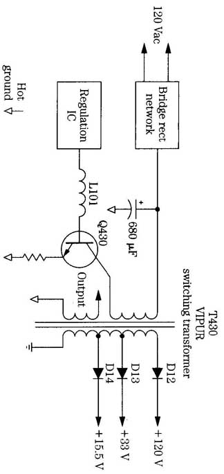
FIG. 12 Notice the input circuits have a hot ground, while the secondary
circuits of T430 have a regular common ground. T430 VIPUR switching transformer;
120VAC; Hot ground.
Running hot:
Smoking resistors indicate a leaky transistor, IC, or capacitor. Power transformers running red hot might be caused by leaky silicon diodes or electrolytic capacitors. Red-hot power output transistors and IC components might be leaky with burned bias resistors. Replace overheated IC components that have a chipped area or white and brown spots on the body.
Check the PC board where overheated parts are tied into the PC board wiring. Often, brown spots on the top, around heated terminals, indicate a poor soldered joint. Clean the area and resolder. If the terminal lead won’t take solder, cut off the bad terminal end, insert the lead through the PC board hole and solder.
Too hot to touch:
A dead high-powered amplifier with a loud hum can be caused by a red-hot output transistor. Red-hot output transistors in the car radio might have burned open the fuse and charred the hot wire to the receiver. When the horizontal output transistor in the TV chassis runs red hot, suspect insufficient drive voltage or a leaky output transistor. Suspect too hot to touch transistors that are leaky or have improper bias voltage.
Check the transistor in the circuit for leaky condition. You might find one transistor leaky and the other push-pull transistor open. Remove both transistors, and test out of the circuit. Always replace both transistors when one is found leaky or shorted ( FIG. 13). Inspect the bias resistors for burned or charred areas. Check each bias resistor and diode while the transistors are out of the circuit.
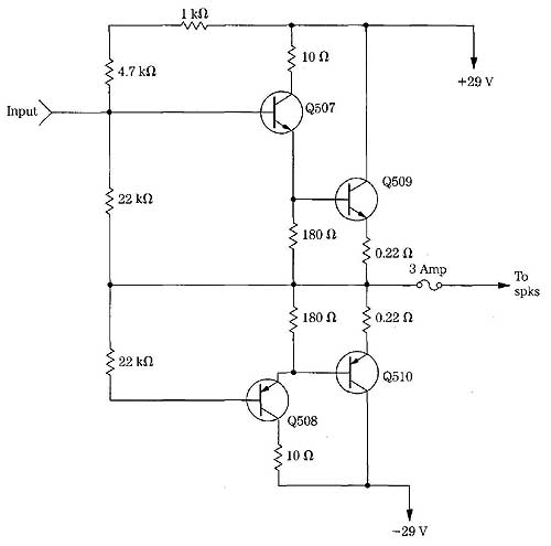
FIG. 13 Check and test all directly driven transistors for open or leaky
conditions with a hot output transistor or IC.
Red-hot audio output ICs indicate a leaky IC or excessive supply voltage. Most output ICs and transistors will run warm, but not red hot. Check for a change in bias resistors and high-power supply voltage. Often, when a red-hot IC or transistor is found, the bias resistors are burned or changed in value. Check for leaky directly driven transistors when the output transistor or IC runs red hot.
Another chassis:
If you have a new TV chassis that has quit and have no schematic, compare it with another chassis. Sometimes, even with a schematic, certain voltages are not listed, and with another chassis, you can compare voltage and resistance readings. Of course, the chassis must be the same make and have the same chassis setup. Comparison tests can solve a difficult problem when a schematic is not handy.
Often the circuits within TVs, stereos, and radios are the same for several years. If you have a schematic for an older unit, use it. You can also compare the chassis with another brand. If the defective chassis has marked part numbers, use a schematic that is similar (FIG. 14).
Take voltage measurements of a transistor from each terminal to common ground. With an NPN transistor, the positive lead will go to each terminal with the negative probe grounded. Just reverse the test leads for voltage measurements of a PNP transistor. The positive probe is at ground potential with a PNP-type transistor. Use a DMM for accurate low-voltage tests.
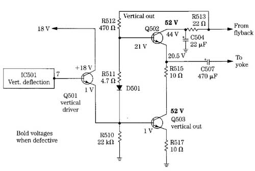
FIG. 14 A schematic of a vertical output circuit of a case history with
actual voltage measurements. vertical out; From flyback; To yoke; 18V; R512;
Q501; vertical driver; C507 470 uF; Bold voltages when defective; R510 22
k-ohm
Most voltage tests on a suspected IC should be made with the positive lead at the IC terminals and the negative probe clipped to ground. Write down the voltage measurements on each terminal pin. Then determine if these voltages are correct. Al ways check the voltage supply pin first. If the voltage is very low, suspect a leaky IC.
Remove the voltage-supply terminal from the PC board wiring to see if the voltage increases. Simply unsolder the pin with solder wick and a hot iron. Flick the pin to make sure it’s loose and not touching the PC board wiring. Now take another voltage measurement. If the voltage has increased to normal or higher, replace the leaky IC.
Inmost linear transistor voltage tests, the NPN transistor collector voltage will be the highest reading, with the base terminal voltage next, and the emitter voltage is the lowest ( FIG. 15). Likewise in a PNP transistor, the emitter terminal has the highest voltage, the base terminal is next, and the collector voltage is the lowest. Zero voltage on the emitter terminal can indicate an open transistor or emitter resistor.
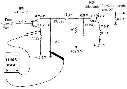
FIG. 15 The collector terminal of an NPN transistor has the highest positive
voltage.
When making high-voltage tests, such as on the anode terminal of the CRT, use either a high-voltage probe or a high-voltage probe attached to the VTVM. High-voltage tests on microwave ovens should be made with a high-voltage probe or Magnameter. Make sure the ground clip is attached to the chassis, or you will receive a shock from the high-voltage probe.
Resistance measurements
Critical resistance measurements on the terminals of a transistor or IC to common ground might locate the leaky part. Resistance measurements in transistor and diode tests with the DMM might determine if a suspected part is open or leaky. Critical resistance measurements on the emitter or bias resistors might indicate a leaky transistor or IC or a change in resistance ( FIG. 16).
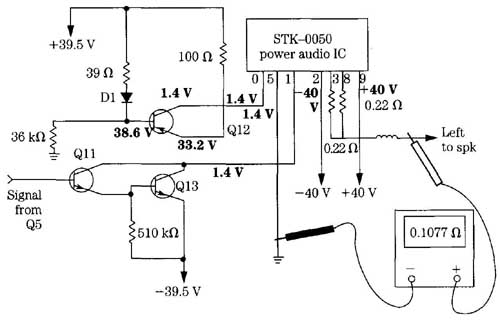
FIG. 16 Make critical resistance measurements upon the audio output power
IC to locate a defective AF or driver transistor.
Within the audio amplifier, accurate resistance measurements on the speaker output terminals, with the speaker removed, can indicate a defective transistor or IC or a change in resistance. Safe resistance measurements can be made with the power off when an output IC runs hot. Comparable resistance measurements in the stereo channels might help locate the defective part. Of course, a resistance or continuity check of each component might turn up a defective part. Very few schematics show the resistance measurements to ground ( FIG. 17).
Continuity checks:
A continuity or resistance check of a component is a quick way to determine if the part is open or leaky. Check the speaker terminals to see if the voice coil is open or grounded to the speaker magnet or framework ( FIG. 18). When taking speaker measurements with a DMM, the resistance should be quite close to the speaker impedance. With a VOM the resistance might be off 1 or 2 .
Continuity tests on the tape head can determine if the winding is open. Place extra pressure on the tape head terminals if the winding is suspected of intermittent playback. The continuity test between the tape head terminal and the outside shield might help clear up the problem of weak or distorted tape player sound ( FIG. 19).
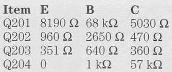
FIG. 17 Resistance measurements are found from various terminals of transistors
and ICs to ground.
Continuity checks of any component can determine if the part is open. For example, the resistance of a tape, VCR, or CD motor might not be known, but a continuity test across the terminals can indicate if the motor winding is open or if there is a broken connection. Likewise, check switches, coils, and transformer connections with a continuity test.
After installing a flyback transformer or IC component that solders directly to the PC board, you should make continuity tests of the PC board wiring. Check from the actual terminal pin to the next part tied to the same wiring to determine if the PC board wiring is intact. Sometimes the PC board wiring breaks at eyelets or terminal pins. Bridge the wiring and resolder.
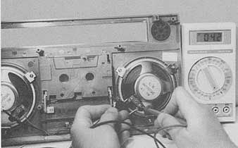
FIG. 18 Check the speaker terminals with a continuity test for open conditions.
Waveform tests:
Critical waveforms can determine if a signal is missing or present within the TV, stereo amplifier, or computer. Waveforms taken on the deflection IC or processor can find an open IC without any horizontal or vertical output pulse. Check for a defective vertical oscillator transistor or IC when the sawtooth waveform is not found on the input terminal ( FIG. 20).
The horizontal waveform can be checked from the countdown (deflection) IC or transistor oscillator circuit to the horizontal driver transistor. Check the horizontal pulse at the driver collector terminal and base terminal of the horizontal output transistor. Of course, a quick waveform check of the flyback will indicate if the horizontal circuits are functioning ( FIG. 21). Knowing where and how to take critical waveforms can save a lot of time. Check the video waveform upon the base terminal of the first video amp with on the air broadcast signal ( FIG. 22).
Time to vaccinate:
Injecting an audio or RF signal into a radio or audio amplifier can isolate the dead or weak stage. Signal RF injection in the radio receiver front-end section can quickly indicate a defective circuit ( FIG. 23). A 1-kHz audio signal injected throughout the audio circuits of a dead or weak amplifier can quickly locate the defective stage. The radio or amplifier speakers can be the indicator.
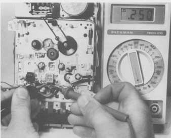
FIG. 19 A resistance tape head measurement can determine if winding is
open, shorted, or grounded.
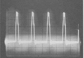
FIG. 21 Place the scope probe near the flyback to determine if the horizontal
circuits are functioning.
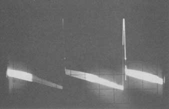
FIG. 20 The vertical output waveform will indicate if the output IC or
transistor is defective.
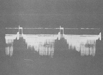
FIG. 22 The on-air broadcast waveform at the base of the first video amp
in the TV circuits.
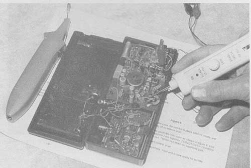
FIG. 23 Signal injection of a radio, cassette, or amplifier will quickly
determine what stage is defective.
When injecting an audio signal into the amplifier, a separate audio amplifier can be used to hear the weak or distorted sound. Signal injection from the audio signal generator into the input of each audio stage can quickly locate the defective circuit. Audio comparison tests can be made within the stereo audio circuits by injecting a 1-kHz or 3-kHz signal into the input of each left and right channel, then comparing the audio signal at several points in the circuit and comparing the signals.
When isolating a defective audio circuit within the TV, cassette player, and amplifier, start at the volume control by injecting a 1-kHz signal at the center top of control, with no schematic. If the sound is normal, suspect the input audio signal circuit. Double-check the audio signal at both center top terminals of the left and right stereo volume controls. Proceed towards the speakers with weak or no signal. Go from base to base of each audio transistor. Remember, as you proceed to the last set of transistors, the audio signal becomes higher. When the weak, distorted, or dead stage is found, take critical voltage and resistance measurements upon transistors or IC components.
External amp
The audio external amplifier can consist of a single IC amp or two or more transistors with self-enclosed pin speaker ( FIG. 24). The external audio amplifier can be used to quickly locate a defective stage or circuit in the audio stages, by injecting a 1-kHz audio signal at the input of the amplifier circuits from a generator and using the external amp to trace the audio signal through the audio circuits. Go from base to collector terminals to note the increase in audio signal. Keep the gain of the audio signal generator as low as possible for an audible tone. This audio signal can be signal traced right up to the speaker terminals.
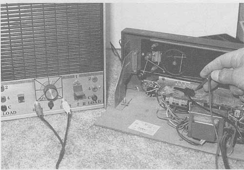
FIG. 24 Use the external amp for troubleshooting audio circuits.
When checking for a loss of audio signal in the cassette player, insert a 1-kHz or 3- kHz cassette and check the audio signal at the tape head ungrounded connection with the audio amp. Check the amplifier signal at the volume control. Test both channels for audio signal at the volume control and compare the signals. If one channel is lower than the other, suspect a defective pre-amp transistor or IC ( FIG. 25). Go from base to base of the pre-amp transistors or IC to locate the defective component. A pre-amp IC between the tape head and volume control is easy to locate upon the PC board.
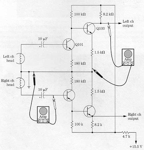
FIG. 25 The cassette pre-amp circuit can be signal-traced with an external
amp and cassette.
How to test transistors:
Check each transistor in or out of the circuit with the transistor test or transistor-diode test of the DMM. When checking transistors in the circuit, watch for choke coils, low-ohm resistors, and diodes within the circuit. Low or improper measurements might occur. Don’t overlook a defective transistor in the circuit that might be open or leaky but that, when removed, tests normal. Sometimes heat on the transistor terminals can restore the transistor. Replace it anyway.
Always test a transistor after removing it from the PC board. Spray coolant or heat on the transistor to make it act up. Don’t forget to check the replacement before soldering it onto the board. Check the bias resistors before replacing a transistor.
The suspected transistor can be checked in the circuit with voltage tests. Low collector voltage can indicate a leaky transistor. All close voltages on the three terminals of the transistor can indicate a leaky transistor. Higher-than-normal voltage on the collector terminal can indicate an open transistor. No emitter voltage can indicate the transistor is open.
Take a voltage measurement between the base and emitter terminals for correct bias voltage. An NPN transistor should have a 0.6-V measurement, and a PNP transistor should have a 0.3-V reading. If an improper measurement is found, the transistor is defective.
Accurate transistor tests can be made with the diode test of the DMM. Most of the latest DMMs have this diode test for checking the junction resistance between terminals. A very low measurement between the collector and emitter terminals indicates a leaky transistor ( FIG. 26). Most leaky conditions found in transistors are between the emitter and collector elements.
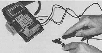
FIG. 26 Check the suspected transistor with DMM diode-transistor test.
When checking an NPN transistor, place the red probe on the base terminal and place the black probe on the collector terminal. If you get a low resistance reading, under 100 ohm, suspect leakage between the base and collector elements. The normal measurement is above 500 ohm.
Let’s say the measurement is 877 ohm ( FIG. 27). Place the black probe on the emitter terminal and leave the red probe at the base terminal. The transistor is normal if a comparable measurement is noted (845 ohm).
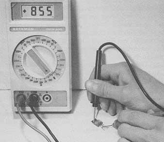
FIG. 27 Place the red probe (+) to the base terminal and the black probe
(-) to either the cal lector or emitter for a comparison junction-diode
test.
When the reading is low between any two elements between these elements. You might find that a transistor leaks between all three elements. Often a leaky transistor occurs between the collector and emitter terminals. When a junction test is high on one set of elements and not the other, it’s likely that the transistor has a high and poor junction; replace it.
When making transistor tests on a PNP transistor, the black probe stays on the base terminal while taking measurements with the red probe on the collector and emitter terminals. Remember, low resistance measurements can be caused by small coils, chokes, diodes, and low-ohm resistors in the base circuits. In this case, remove the base terminal from the PC board wiring and take another test.
NPN or PNP
Although you will find that most transistors in later chassis are NPN types, be prepared for a few PNP types. When no schematic is handy and you don’t know which terminal is the base or collector, try the diode test. Determine if the transistor has a part number on the body or marked terminals. Look up the part number in the replacement manual to tell if it’s an NPN or PNP type, what its working voltage is, and what circuits it’s found lit.
If there are no part or terminal numbers on the transistor, try to locate the base terminal with the diode test. In a normal transistor, the base is tested with the positive probe of the DMM, and the resistance is common to both the collector and emitter terminals. Usually a higher resistance measurement is from base terminal to emitter. For example, in testing an SK3710 horizontal deflection output transistor, the resistance, with the red probe on the base terminal and the black on the collector, is 609 ohm. The resistance measured from the base to the emitter terminal is higher at 667 ohm.
Also, this measurement indicates that the transistor is normal and an NPN type. When the measurement is common with the red probe at the base terminal, it’s an NPN transistor ( FIG. 28). Try checking any transistor out of the circuit with this method.
Another method to tell which terminal is base or collector is to take accurate voltage measurements. The highest voltage is found on the collector terminal of an NPN transistor and common ground. Check (with the power off) for the lowest resistance to ground, which indicates the emitter terminal. Now use the remaining terminal (base), and test the transistor with a beta transistor in-circuit tester.
SK3710 NPN transistor
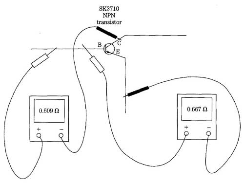
FIG. 28 Normal diode transistor DMM test of an RCA SK3710 output transistor.
Checking diodes
Fixed diodes can be checked with the ohmmeter or diode test of the DMM. The DMM is quite accurate in determining if a diode is leaky, open, or of the correct polarity. Connect the red probe of the DMM to the anode (—) terminal of the diode and the black probe to the cathode (÷) terminal. You should have a measurement of about 500 or higher. Measurements below 100 I indicate leakage. Now reverse the test leads; no reading means the diode is normal ( FIG. 29). A low measurement in both directions indicates the diode is leaky.
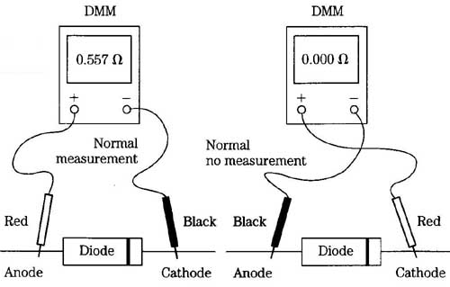
FIG. 29 Suspect a leaky diode with a low resistance measurement in both
direction. Here the diode tests good.
Zener, detection, and damper diodes must be checked in the same manner. The resistance of a normal RF diode (1N34 or 1N60) can have a higher resistance in one direction above 1 k-ohm. All diodes checked on the resistance scale of a VOM will have a low resistance reading with the red probe on the cathode terminal and the black probe on the anode. Notice this reading is just the reverse of a DMM diode measurement.
High-voltage diodes found in black-and-white TVs and microwave ovens won’t test with the DMM diode test. High-voltage diodes on a 2000-Me resistance scale will show a measurement above 10 M with the black probe at the cathode terminal, and infinity with the test leads reversed.
Checking ICs:
Integrated components can be checked with signal in and out tests. Likewise, scope waveforms taken at the input terminal of a vertical output IC can be seen and amplified at the output pin. An audio signal found on the output IC can be heard on the output terminal if the IC is normal.
Normal measurement; Normal no measurement
Black
Anode
Anode; Cathode
Critical voltage measurements on each IC terminal will indicate if the part is open, leaky, or shorted. Check the supply voltage pin (Vcc) for higher voltage. Often, low supply voltage at the voltage source terminal indicates a leaky IC or improper applied voltage. Take critical resistance measurements from each pin to the chassis ground to locate leaky parts tied to the IC circuits ( FIG. 30). Visually trace the pin wiring when a low measurement is found.
In the stereo audio chassis, compare the voltage and resistance measurements to the normal IC or transistor. If the voltage and resistance readings are way off, suspect a leaky IC or directly coupled transistor. Leaky or open transistors within the pre-amp and driver directly coupled circuits can change the voltage measurements on the output IC.
Defective boards:
Cracked boards can cause intermittent operation. Broken boards are difficult to replace. Sometimes placing extra pressure on sections of the board can cause the intermittent to act up. Place a strong light over the board, and use a magnifying glass to help search for cracked wiring. Fine breaks can occur around heavy parts or chassis standoffs.
Bad soldered connections at terminal pins of components and ICs can produce intermittent sound in a TV chassis ( FIG. 31). Large blobs of solder on part terminals can cause a dead or intermittent chassis. Brown areas around terminals can mean poor soldered connections or overheated parts. Sometimes resoldering the en tire board section can solve this problem. Be careful not to overlap solder to another terminal or PC board wiring.
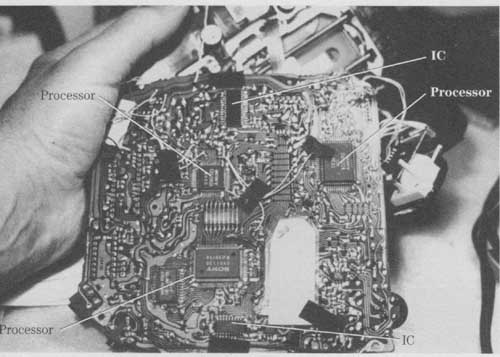
FIG. 30 A critical leak measurement of IC pins to ground can identify
a leaky component.
Intermittent problems:
The intermittent chassis is the most difficult problem to repair and can be very time-consuming. Try to locate or isolate the intermittent with all the symptoms that are produced. Monitor the suspected section with voltage and scope tests. Within the audio system, use the speaker as an indicator. An oscilloscope can be used in areas where waveforms are found.
Coolant and heat sprayed on the suspected capacitor, transistor, or IC might make it act up or quit. Several applications might be needed before you get any results. Most intermittent components are found by monitoring the chassis with a volt meter and scope until the unit acts up.
Intermittent parts in the audio stereo chassis can be located by comparing the signal in the normal channel. Critical voltage measurements on each channel at a given point can uncover the intermittent part. Sometimes just moving the board or component can cause the sound to come and go. Check for intermittent coupling capacitors, transistors, and IC components in the stereo channels.
 FIG. 31 Check for a poor board connection for intermittent operation in
a TV chassis.
FIG. 31 Check for a poor board connection for intermittent operation in
a TV chassis.
Overheated transistors or IC components in the TV chassis can produce intermittent symptoms. Intermittent horizontal circuits are very difficult, to find because derived secondary voltages are required to make the circuits operate. Look for small things, such as poor connections, bad soldered joints, poorly soldered transistor pins, defective or corroded sockets, and bad board connections.
Part replacement:
After locating the defective part, locating a replacement can be most difficult. Sometimes the correct part is hard to find. Substituting another component might be the only answer. Electrolytic and bypass capacitors, resistors, and large-wattage resistors are easy to find. Special transistors and IC parts can be replaced with universal replacements found in the semiconductor manual. Transformers, coils, motors, and original replacement parts might be difficult to locate.
Always try to replace defective parts with the original component. Critical parts found in special safety areas should be original part numbers. It’s difficult to substitute for the special tape motors found in VCRs or CD players ( FIG. 32). Tuners found in TV chassis or VCRs can be replaced with new units, or they can be sent in for repair at a manufacturer’s service center.
Besides local wholesale electronics parts stores, manufacturer’s service centers, and parts distributors, try obtaining certain parts from mail-order firms. It might take a few days, but they might have the part to fix that chassis that is collecting dust. Don’t overlook the fellow technician down the street. Sometimes certain parts might be found just next door.
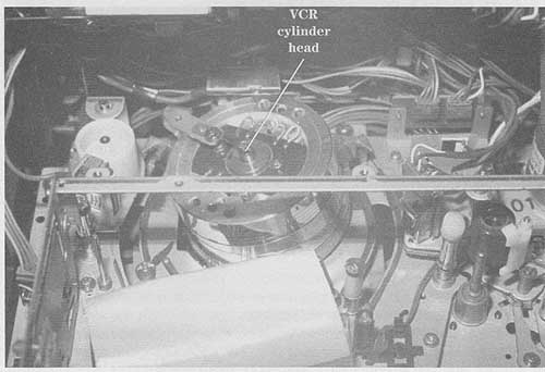
FIG. 32 Replace all motors and the VCR or camcorder head cylinder with
the original part number.
Way down under:
Surface-mounted components (SMD) are mounted under the chassis in the TV set. These components are found mounted and soldered directly upon the PC wiring, while standard parts are found upon the top side of the chassis board ( FIG. 33). Extreme care must be exercised not to flex the PC board or drag the chassis across the work bench to prevent damaging the SMD components.
The surface-mounted devices are soldered at each end to the foil of PC wiring. An SMD resistor or capacitor can be flat or round. It can be found mounted any where under the TV chassis. Notice that several fiat SMD parts are even mounted between the large IC that is mounted on top with the pin terminals soldered to the PC wiring ( FIG. 34).
SMD parts:
The surface-mounted device might consist of a fixed resistor, capacitor, diode, transistors, ICs, and microprocessors. You might find more than one resistor or diode inside one SMD component. Of course, transistors have three separate terminals, and IC components have many pin terminals ( FIG. 35). ICs, CPUs, and microprocessors might have gull-type mounting wings. Don’t be alarmed when a resistance measurement upon a diode- or resistor-looking device turns out to be nothing more than a solid feedthrough. These feedthrough devices attach two circuits together.
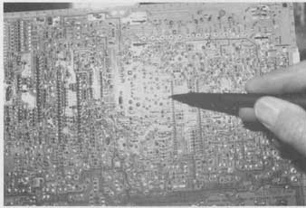
FIG. 33 The pen points at a small SMD component.
SMD components are tested in the very same way as those mounted upon the top side of the chassis. To take resistance, voltage, and transistor measurements, sharpen the points of the test probes. If a schematic or parts layout is not available, it’s very difficult to tell the difference between parts, Of course, a resistor will have resistance while a capacitor should not. A feedthrough SMD will have a dead short or zero resistance.
The digital transistor might have the base and bias resistors mounted inside the surface-mounted component, while the standard resistor has leads directly to the internal elements. Note that the PNP digital transistor has the base and bias resistors tied to the emitter terminal ( FIG. 36). Likewise, the NPN transistor is the same. When making transistor tests on digital transistors, allow for the resistor in series with the base terminal and a resistance leakage between the base and emitter terminals.
Removing surface-mounted components:
To remove a defective resistor or capacitor, remove the solder at one end. A solder wick and the soldering iron can be used at each end to remove excess solder. Hold the part with a pair of tweezers, and twist as the component is removed. Throw away all surface-mounted parts removed from the chassis. They should not be used, once removed.
To remove a transistor or diode SMD, melt the solder at one end and lift the leads upward with a pair of tweezers. Do this to each terminal until all are removed. Some larger components might be glued underneath. Cementing the new SMD is not necessary. Remove jagged or overlapped solder from the PC wiring. Clean off lumps of solder from the wiring with the soldering iron and solder wick.
FIG. 34 SMD parts mounted IC pin terminal on the PCB trace side.
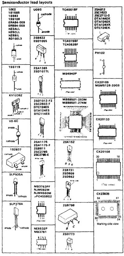
FIG. 35 The various SMD ICs and transistors found in a consumer electronic
product.
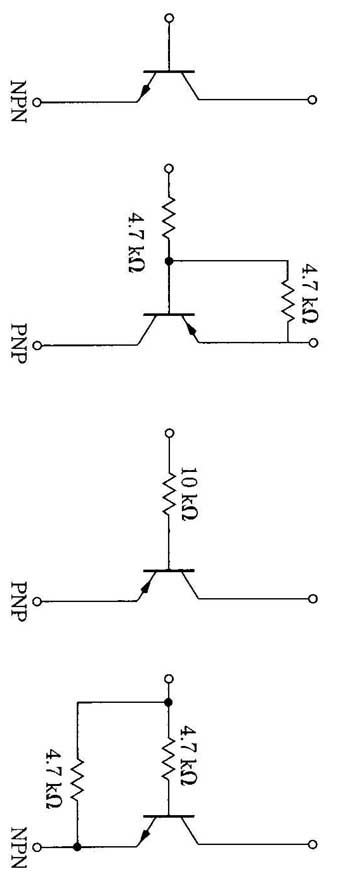
FIG. 36 Digital transistors have base and emitter resistors inside the
same body.
In removing flat pack ICs, apply the soldering iron to each pin terminal, and lift solder with solder mesh material. Another method is to unsolder one terminal with the soldering iron and pry up the pin terminal with a sharp tool. Some electronic technicians use a butane-fueled soldering pen, which is found at most electronic distributors. The pen is held about 1“ from the flat-pin terminal and pried up with a small screwdriver blade or sharp-pointed tool.
With the gull-wing IC or microprocessor, many terminals can be removed by cut ting each pin terminal near the body of the IC. Place a long resistor terminal along side the body and then cut each pin towards the IC body. When all pins are cut, lift the leadless body off the board. Remove each cut terminal with the soldering iron and tweezers. Be very careful not to cut into the foil pattern. Also, don’t apply too much heat on one area to lift the foil from the PC board.
SMD replacement:
Universal SMD fixed capacitors and resistors can be used to replace a defective component. These universal components can be purchased with a card of different values. Always use direct factory replacements with dual resistors and diodes, transistors, ICs, and microprocessors.
Remove any solder left upon the PC wiring with a desoldering braid or solder wick. Clean the entire area with cleaning fluid, acetone, and a stiff brush. Make sure the mounting area is clean and level.
When installing new SMD ICs and microprocessors, connect an electrostatic discharge strap to your arm and clip to the ground area of chassis. Position the replacement SMD IC exactly in the correct place. Observe terminal number 1. Place solder flux over each SMD pin. Tack down each corner terminal of the SMD part with solder. Carefully solder up each terminal pin, making certain two separate terminals are not soldered together. Check the connections out with the low resistance of the DMM.
FIG. 37 A card of SMD universal resistors.
EST FCC ID numbers
Every VCR, cordless telephone, personal computer, and microwave oven must carry an FCC ID number. The first three characters of that ID identifies the manufacturer of the product. When a unit comes in and the make is not known, look it up in FIG. 38. Often the standard life of TVs, VCRs, stereos, or other consumer electronic products is between 7 and 10 years. Of course, there are many electronic components out there that are quite a few years older. You might find that parts and service literature are not available over the 10-year period. Check the correct prefix of the manufacturer and contact them for special components.
Clean up:
Blow out dust and dirt from on top and inside the electronic chassis. Clean up the radio dial numbers and frequency letters before placing the product upon the finished bench. Wipe off the front of the TV screen, and wash the dial assembly and dirty knobs with window spray. Clean off the plastic or wood cabinet that might have color marks, dirt, and fingerprint smudges. Replace all chassis and back cover screws. Make that electronic component shine like new before it’s returned.
FIG. 38 The FCC ID numbers and letters found on every CD/DVD/BluRay, cordless telephone, personal computer, and microwave oven.
Also see:
Repairing the deluxe amplifier
. ===