Removing Frozen Yokes
Now and then the TV serviceman is plagued by the necessity of removing a "frozen" yoke. If solvent applied around the neck of the picture tube fails to loosen the yoke, many manufacturers recommend the application of a suitable AC voltage (25 to 50 volts) to the yoke's horizontal windings. To reduce the line voltage, a variable voltage transformer is often recommended. The use of this device may be impractical for at least two reasons: less expensive transformers of this type do not permit a sufficiently gradual variation of voltage output in the desired range, introducing the danger of yoke damage; and many service shops do not have such a transformer available at all. The following method requires an accessory that can be assembled easily and inexpensively:
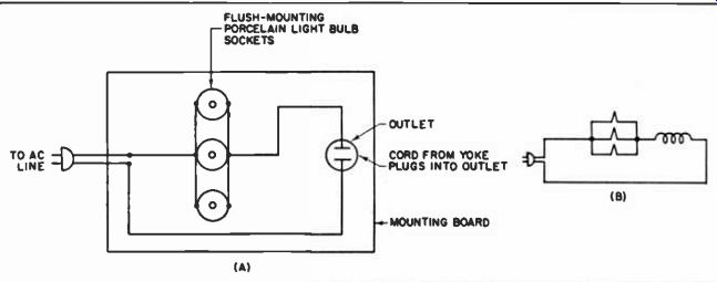
-------------- Set-up for removing frozen yokes. Porcelain sockets can
be readily mounted on a board.
Arrange three light-bulb sockets, an outlet and a line cord in the manner shown. Attach one end of a line-cord wire, to the other end of which a male plug has been connected, to the horizontal section of the yoke.
(First disconnect the yoke from the circuit, of course.) Insert this male plug into the socket on the test device. By screwing various sizes of electric bulbs into the three parallel sockets, enough heat will be generated in the yoke so that it can be slipped off. Use the smallest wattage (highest resistance) bulbs that will do the trick. Application of some vaseline or similar lubricant to the portion of the CRT neck over which the yoke must slide may prove helpful. Remove the yoke with a gentle, rocking motion.
Note that the light-bulb sockets are electrically in parallel with each other, but in series with the yoke and the Ac line. Using higher wattage bulbs or placing bulbs in parallel reduces the resistance in series with the yoke. This increases current and voltage in the yoke's windings.
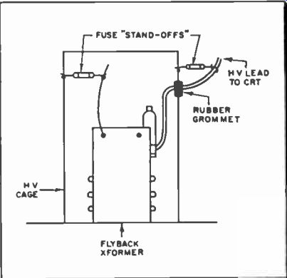
Unique HV Standoff
Don't throw those burned-out pigtail fuses away! When trying to dress leads inside high voltage cages, and in similar applications when it is desired to keep leads fixed in desired positions, the burned-out pigtail fuses can be used as anchors. Since the fuse is blown, the glass envelope provides effective high voltage insulation. As with cellulose tape, the applications for these fuse "standoffs" are only limited by the technician's ingenuity. The pigtails are used for tying purposes. Some possibilities are illustrated.
----------
Fuse Saver
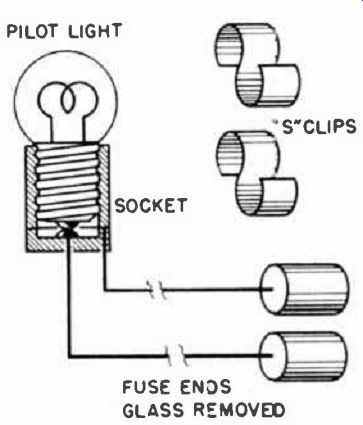
------------ Pilot light adaptor speeds troubleshooting.
When repairing a TV receiver having a defective or intermittent horizontal sweep circuit, continuous replacement of the fuse can be quite bothersome. I made a little gadget out of an old fuse, pilot light socket and some wire as shown in the diagram. Remove all the glass from the end caps of the old fuse. (No sense in ruining a new fuse.) Solder two wires to the caps and a pilot-light socket. A pair of "S" clips enables me to hook up my little device to any pigtail fuse. Where the fuse snaps in, just insert the end caps of this gimmick in place of the fuse.
The use of a pilot light in place of a fuse will permit an approximate overload of 1 1/2 times without blowing out and at the same time afford some protection. The brightness level in the bulb is a rough indication of the amount of current in the circuit. A 6.8-volt, 250-ma pilot lamp, #46 and a 2.5-volt, 0.5 ampere lamp, #43, can be used in place of 1/4 and 1/2 ampere fuses respectively.
Transformer Repair
---p41 While maintaining slight pressure on warped plastic wafers of a coil, heat is applied to correct intermittent failure.
Slug-tuned I-F and similar type transformers used in TV and radio, require capacitors to form parallel resonant circuits. On the older types these were regular capacitors which were wired inside or outside the transformer can. On current type transformers the capacitors are formed by silver-plating both sides of a piece of mica and then sandwiching it between two plastic wafers at the base of the transformer. The sandwiching forms the necessary connections by pressure contacts.
I have found that many of these transformers, especially those used in audio detector circuits, become defective due to warping of the plastic wafers. When this warping occurs it releases the pressure contacts and produces intermit tents, circuit failure after warm-up, and often complete circuit failure. This type of trouble is generally caused by mounting the transformer too close to a heat producing component, such as a power tube, high wattage resistor, or mounting the transformer directly above a hot tube on a vertical chassis. Trying to obtain exact replacements involves a considerable amount of time and using a universal replacement generally leads to complications-especially if the transformer is mounted on a printed circuit board. All these headaches are unnecessary as it is easy to repair this type of defect.
Remove the defective transformer from the chassis and then remove its aluminum shield, thus exposing the coils and capacitor sandwich. Handle the unit carefully as many of these coils are wound with very fine wire which is easily broken. Next, grip the sandwich wafers with a pair of long-nose pliers, as shown at left, and exert a slight pressure. While applying pressure, use a clean soldering pencil to melt the two plastic wafers together near the point where the pressure is being applied. Repeat this procedure on all four edges of the sandwich. This will restore the pressure contacts. The unit is now ready to be reassembled. After the transformer is reinstalled a slight touchup in alignment of the stage may be required.
Fusing the edges of the capacitor sandwich in this way makes future warping almost impossible at temperatures generally encountered in radio and TV receivers.
Transformer First Aid
Here is an idea I have used several times to repair TV sets with open 5U4-filament windings in the power transformer. I replace the 5U4 with a 6AX6 heater-cathode type rectifier tube. I have tried several other tubes of this type but find that the 6AX6 gives the best service. The change is as follows: Remove all leads to the 5U4 socket; connect the plate leads of the power transformer to pins 3 and 5; tie the cathodes, pins 4 and 8 together and connect the B+ lead to pin 4 or 8; connect the heater pins 2 and 7 to the existing 6.3-volt winding on the power transformer and tape the old 5U4 filament leads. The 6AX6 requires 2.5 amperes for heater current; be sure the transformer can handle the extra load.
So as not to compromise the built-in margin of safety, another alternative to replacing the costly power transformer, in the above situation, is to install a separate filament transformer capable of delivering 6.3-volts at 2.5-amperes. If a separate transformer were not used and if a cathode-to-heater short developed, 8+ would leak into the 6.3-volt filament string and cause much damage.
If a separate transformer is used, then the technician may as well get a 5-volt job and continue using the 5U4 tube type. -Ed.
Noisy Tuning Condensers
Quite often a small radio will come in with a complaint of noisy and intermittent tuning. This is often due to fine particles of the plating on tuning gang condensers flaking or powdering off the base metal of the plates, and shorting out as the plates are rotated. This difficulty can be quickly cleared up by removing the gang assembly from the chassis and giving it a bath in muriatic acid for a few minutes.
This acid, which is very inexpensive, can be purchased in a local paint shop.
The tuning assembly is then bathed in water, rinsed in denatured alcohol and allowed to dry.
When re-assembling the tuning unit into the set, make doubly sure that the oscillator and r-f trimmers are dry. Re-align the oscillator and r-f stages as usual, lubricate pivot points and bearings and--presto--clean, noiseless tuning.
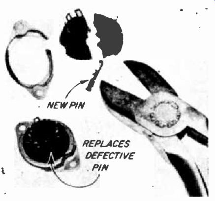
---------- A new socket pin avoids time-consuming replacement of an entire
defective socket.
Tube Socket Repair
On occasion, a tube socket pin may break and a spare pin is not readily available. Rather than replace the entire defective socket with a similar type usually stocked, repairing the socket will save considerable time and avoid the possibility of a wiring error.
Cut the bakelite of a similar type socket with a pair of diagonal cutters and remove a good pin. See above.
Then, remove the broken pin of the original socket by exerting pressure from the bottom with a small punch or screwdriver. Insert the new pin into the original socket from the top of the chassis, pulling it through with needle nose pliers.
Salvage Handy Connectors
Small 45 and 67% volt batteries are usually provided with one male and one female snap connector.
When these batteries are discarded, I remove the fiber strip holding these connectors and save it. A pair of these make a very good connector for speaker leads or other two-wire arrangements. They are heavy and make excellent contact.
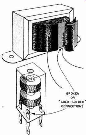
---------- Breaks usually occur at these points.
Transformer First Aid
What may appear to be a transformer replacement job in a fairly new set may in fact turn out to be only a minor repair to a major component. In many cases a winding which reads open or very high resistance may be due to a defective or broken solder joint inside the transformer, where the heavy leads are attached to the comparatively very thin winding ends. Power, audio output, I-F transformers, chokes and other coils may suffer from this difficulty. All that is needed is to clean and re-solder the joint to restore the transformer to operating condition. It is more likely that this condition will be found in new equipment. Breakdown in older transformers usually occurs within the windings. In some cases it is possible to dig the coil, find the trouble and correct it. The chances for breakdown are ever present in the latter procedure and is therefore not usually recommended. With a sharp knife, cut one layer or insulation at a time and fold back. Cut only as many layers as needed to expose the coil winding ends. Precaution against cutting too deep should be exercised to avoid damaging the transformer coil windings.
Extreme care should be exercised in preparing the short coil ends for connection, a break too close to the coil proper may terminate any further first aid procedure. Use fine emery cloth to remove the enamel coating. It is a good idea to provide strain relief on these leads. Fold the insulation back into place and tape.
Quick Fuse Mount
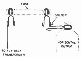
--------- Improvised fuse holder.
On sets not already equipped with a fused flyback and where space permits, I have been able to modify and satisfy at a very nominal cost.
Simply by soldering 2 spring clips and affixing them to the top of the 6BG6 or 6BQ6. Place an appropriate size fuse between these clips and the lead from the high voltage transformer. Of the 2 clip sizes available, select the smaller one to hold the fuse.
Noisy Tuning Condensers
Curing a noisy tuning condenser by flashing with high voltage is a pretty well known trick by now. But, that involves disconnecting all components from the tuning gang, such as the antenna loop, rf transformer, etc. This can be quite a tedious job on some sets. A high-voltage supply must also be available. Even so, I have occasionally run into stubborn cases which just won't clear up, with the flashing and burning technique.
The latest trick is one which requires no unsoldering or high voltage supply and even works in stubborn situations. Just grab that can of high-dielectric plastic spray and cover both the rotor and stator with a generous coating. Allow to dry thoroughly. The loose particles are trapped in the plastic. The gang works smoothly and without noise.
When repeated complaints occur or when flaking becomes excessive, the best solution is to replace the condenser. If you must effect a permanent repair on the old job, then remove the tuning gang from the receiver and strip it of trimmer mica and screws. Immerse the gang in a bath of killed acid (muriatie acid with some zinc) until the coating has been removed. Then thoroughly wash in a bath of alcohol to neutralize and stop any further action. Avoid excessive "cooking." -Ed.
Inaccessible Tubes
When it becomes necessary to replace the larger 6AF4 tube type, and only the smaller 6AF4A is available, the technician may find that the tube fits into a deep recess.
If the smaller 6AF4A tube is used, he will find much to his sorrow that he will be unable to remove it for future replacement. I recommend the use of a 3-inch length of 3/4-inch wide plastic high-dielectric tape. The smaller 6AF4A is pushed through the tape, gum side up, so that the pins make their own holes. The tape is then folded up along the sides of the tube and squeezed together so as to form a tab. This hint may be used in other inaccessible places provided the tube is not operating at a high temperature.
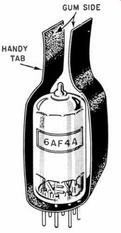
-------- Heat and shield conditions permitting, plastic tape forms handle
for miniature tubes.
Binding in Dual Controls
When two TV control knobs are mounted one in front of the other on concentric shafts, there is always the danger of their sticking together.
It seems that, if the hole on the outer (more forward) knob is deep enough, people adjusting their sets invariably manage to push this front knob against the inner one-thus making it impossible to turn one of them without having the other also move.
Since the cause is excessive depth of the hole in the outer knob, this trouble can be prevented by using little pieces of solder to fill the hole until its depth has been reduced by a satisfactory amount. With the right amount of filler, the outer knob cannot be jammed against the inner one.
Solder is the recommended material because it is easily mashed into the proper shape, and is thus prevented from falling out.
Component Installation
I've always run into difficulties trying to install some components into their respective holes in a printed circuit board. Attempting to space and thread long flexible leads of transistors, diodes, etc. was a tedious task until I clipped each lead, as illustrated here (above), a quarter inch shorter than the previous one. This enabled me to insert the leads one at a time without any difficulty.
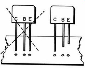
----- Ease the job of inserting individual transistor leads into their
mountings by cutting the leads to different lengths
Switch Replacement
To replace a defective switch mounted on the back end of a potentiometer, without having to go to the expense of a completely new combination control, I have been using this quick method. In some cases it isn't even necessary to remove the control from the chassis.
Pry the old switch off with a knife-blade or a small screwdriver.
Straighten the tips of the new switch, and cut them down to about 1/16th of an inch. With both control and switch in the on position, place the switch on the control and tack solder in two or three places. Before soldering, check to see that the control is functioning properly. -Ed.
---------- Switch assembly.
Tube Saver
The heat developed in and around the horizontal output tube in the TV receiver, often causes the top cap to become loose and unsoldered. Sometimes the cap remains firmly cemented to the glass and the actual electrical connection becomes intermittent and bad. Between the corroded wire and low-temperature solder used for servicing, it is difficult to establish a good connection just by applying the soldering iron to the top of the tube. If the tube is good, except for this condition, I change the connecter, on the lead from the flyback, to the spring type if it already doesn't have one. I then spread the spring coils over the wire projecting from the top of the tube. To assure a good connection the wire should be cleaned. This can be accomplished by carefully scraping with a knife blade or emery cloth.
When price is a factor; this idea should help improve customer relations. The spring-type connectors can often be salvaged from defective flyback transformers.
To avoid damage to the horizontal-output tube especially when it has been in service for some time, it pays to inspect the condition of the cap before attempting to disconnect the lead. Often the lead connection is stronger than the old bond between the glass and cap. A small screwdriver can be used as a lever to gently lift the connection without applying decapitating pressures. -Ed.
Overheated Resistors
Dual triodes used as TV RF amplifiers, such as the 6BK7, 6BQ7, and 6BZ7, often develop intermittent shorts. When such a defective tube is replaced, go a little further: check the voltage-dropping resistors to the tube. Frequently the tube short results in overheating of these resistors, causing an increase in their resistance value and a subsequent loss of gain. Turn the set on and let the resistors warm up for a while before measuring their value.' Replacing the resistors that have changed in value will restore the set to its original sensitivity.
Emergency Isolation
When the shock hazard becomes a problem especially when working on radio or TV sets whose chassis are tied to one side of the AC power line, an emergency isolation transformer can be quickly hooked up by using any two similar transformers.
Care must be taken not to exceed the transformer's wattage rating.
Two TV power transformers will do.
Where there are multiple windings, it is best to use the heaviest; this is usually the 6.3-volt filament winding. One transformer steps up as much as the other transformer steps down in a symmetrical back-to-back hookup, as shown in the diagram.
(Less a very small loss; the amount depending upon the efficiency of the transformer.) Exposed leads should be taped.
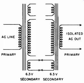
-------- Emergency power line isolation device.
Commercial isolation transformers are available. Some have provisions for raising or lowering the voltage to facilitate certain trouble shooting procedures. -Ed.
Case History File
When replacing components in TV chassis that have to be brought to the shop, I always circle the defective part on the schematic, as illustrated above. If it is an unusual kind of trouble, I will also make explanatory notes in the margin. This provides a case-history record on each schematic, and aids immeasurably in future troubleshooting of the same model.

---------- Circling a defective component and entering symptom on the schematic
simplifies future troubleshooting.
Intermittent Tube Filaments My method of locating intermittent tube filaments cuts down most of the time usually required to "nail" this type of trouble. When an intermittently-open tube filament seems to be present, it can be easily located by shunting a 3/4-watt, 125-volt neon lamp across the heater pins. When the filament opens for even an instant, the neon lamp lights up. I usually place the set on the bench, with the neon lamp hooked to a tube socket, while I work on another set.
If the neon lamp doesn't glow after a reasonable time, I move the lamp to the next socket, continuing this procedure until the open filament is found. On AC-DC sets, a flickering pilot lamp will often indicate the presence of this type of trouble. 50L6's have been found to be frequent offenders.
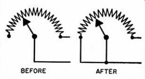
-------- Less noise, and greater life expectancy can be obtained from potentiometers
used in 2-terminal hookups, by connecting the unused terminal to the center
arm.
Quieting Controls
Potentiometers are often used as two-terminal controls in many TV, audio, and other electronic equipment. Noisy controls are quite common, regardless of how they are used. Quieter operation and longer control life can be realized by connecting the unused terminal to the center control arm as shown in the diagram. Should the arm fail to make a good contact, while it is being rotated, the entire pot is in the circuit, arcing tendencies and current surges are thus minimized. The unused portion of the resistance is shorted to the control arm, and does not affect the circuit in any way.
Remove & Replace Tubes

---------- A spin-tight wrench may be used to position the 1X2 tube type
in difficult locations.
Some of the new portable TV sets house the 1X2 high-voltage rectifier tube in almost inaccessible places. To avoid cramped fingers, scraped skin and loss of temper, I insert the cap end of the 1X2 into a 1/4 inch spin-tight nut wrench. If the tube fits too loosely, use tape to build up the area to form a snug fit. When in a hurry to pull a red hot tube instead of burning the fingers or troubling the housewife for one of her pot holders, use an empty tube carton.
Place the open end over the tube, squeeze adequately and pull. When removing or replacing a tube from a printed circuit board, use a rotary motion and avoid excessive pressure to avoid embarrassing breaks. A pin straightener will make life easier, and increase the useful life of a tube socket especially in a tube tester.
Seven and nine pin indexing tabs will cut down some of the time and patience required to install miniature tubes in out-of-the-way and out of the line-of-sight locations. To avoid short circuits when replacing subminiature tubes, avoid excessive length of tube leads. When removing tight top cap connectors from an old horizontal output tube use a screwdriver as a wedge between the cap and connector and avoid any pressure between the glass and cap.
Small Coil Making
Often a small coil is needed of an odd value not readily obtainable.
In such cases, a home-made coil can be quickly fabricated by using a small length of insulation from a piece of coaxial cable as the core.
Cut off the required length of cable; pull the core out from the shielding; and then extract the copper wire through the center. With the soldering iron, heat one end of the wire that will be used to wind the coil, and quickly poke this heated end through the plastic insulation (see the figure). Wrap on the required number of turns and cut the wire to size. Then heat this other end of the wire with the soldering iron and plunge it through the other end of the insulation. You now have a good, low-loss coil, as shown in the illustration.
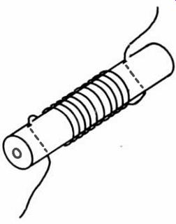
---------- Simple hand-wound coil from cable insulation.
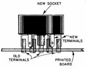
Socket Replacement
Some popular model television receivers use a tube socket that is mounted on metal posts on the printed circuit board. The contacts often break between the socket wafers. Since the replacement sockets when available are not better than the original, we replace them with regular molded sockets, resulting in a more permanent repair.
Carefully break the Formica wafers on the old socket and cut away the metal contacts, leaving the terminal intact on the board. Bend the soldering lugs of the new socket to lineup with the terminals left on the printed board. Slip the center ground contact of the new socket over the similar part of the old socket and solder the lugs to the appropriate terminals.
If the new socket has a mounting bracket, remove it before mounting.
------------
Replacing Socket Lugs
Undoubtedly many of your readers, at one time or another, have broken a lug in a molded socket. Instead of replacing the socket, they have tried to replace the lug, only to have the socket (in a. tuner, of course) also break. To remove the broken lug from the socket, solder a short length of No. 12 or No. 14 wire to the top side of the broken lug and simply pull the wire out. The broken lug will come out with it, and. a replacement may be readily slipped in.
Loose Flyback Ground
We encountered a severe frying and popping noise in a television receiver. The symptom was traced definitely to the flyback transformer.
At first, it was thought that the cause might be one or more defective condensers, resistors, or corrosion in the windings. Close observation of the picture showed no picture pulling, distortion or other adverse effects. Behavior was similar to that when a severe corona discharge is present. The trouble was finally traced to the fact that the iron core of the flyback transformer was not solidly grounded to the chassis, with arcing as the result. Simply tightening the two bolts that fasten the transformer to the chassis corrected the trouble at once.
Loose Miniature Tubes
How often have you run into trouble because a miniature tube would not stay seated in its socket securely? This difficulty, which occurs when the receptacles in the socket become worn or loose, can be remedied quickly: Remove the tube from the defective socket and secure another good socket from your stock. Start inserting the tube into the good socket, but only get it inserted half way. When the tube pins are half way in, give the tube itself a slight twist-just enough so that all of the pins are bent at a slight angle but all in the same direction, so that the spacing of the pins remains the same. Now, when you re-insert the tube in its original socket, you will find that you have a snug 'fit.
Go-No Go Tube Socket Test
To locate a loose pin socket on a 7 or 9-pin miniature tube socket: Carefully remove a pin from the base of a defective 7 or 9-pin tube.
Mount this pin in any suitable holder and probe each opening in the socket.
A snug fit indicates good contact. A loose fit points to a potential trouble spot. Bend the contacts to tighten, and retest. It may be necessary to replace the individual pin holder or the complete socket depending upon the circumstance. I would like to see this idea incorporated in a service tool with a 7-pin probe on one end and an octal on the other.
Determining Open Resistor Values
Occasionally I receive a set in the shop for which I have no schematic.
This doesn't pose a great problem as far as locating the trouble, but a problem does arise when the defective part is not marked with its value. I have found this especially true of wirewound resistors which are seldom marked, or have had their markings burned away by the high temperatures at which these units operate.
To determine the original value of an open wirewound resistor, I file away the insulation at the middle of the resistor, as shown.
This exposes a few turns of the winding. Using an ohmmeter I measure the resistance from this midpoint to each end. One of these readings will be infinity, indicating the open half. The reading obtained on the good half when multiplied by two will be approximately equal to the original value of the resistor. A reading will usually be obtained on one half since it is uncommon for more than one turn to open.
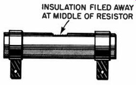
----------- Exposing center coils of a defective wirewound resistor aids
measuring its value.
Vector Socket
Inverted wafer socket permits testing tube voltages from top of chassis.
In many receivers, particularly in early model radios and some portables, components and wiring completely block the path of the underside of a tube's socket.
In the absence of a commercially available test socket, and when it becomes necessary to take readings from above the chassis, a wafer socket, with its lugs flattened, can be inserted between the tube and its socket. The exposed lugs provide readily accessible test points. Note, the wafer socket should be inverted, and the lugs should not come in contact with any chassis hardware.
There may be occasion to modify the wafer socket to make it fit into tight places. This can be easily accomplished with a file or grindstone.
Economy Pilot Bulbs
Instead of using 6-watt 115-volt bulbs as pilot lamps in set-ups of shop or test equipment, as in panel set-ups, use a 200,000-ohm resistor in series with a NE-2T pigtail-type neon lamp. Put this combination across the 115-volt line. This cuts current consumption from 6 watts for each bulb down to about 1/25 of a watt. Space is also saved by mounting the little bulbs in grommets with 1/4-in. inside diameter, for a perfect fit. These neon bulbs can also be used to replace the regular 6-watt lamps in dial lighting and indicator applications.
Transistor Mounting
In many cases where the transistor is suspected as being defective, it must be unsoldered from the circuit for a final check or substitution.
Whether it proved to be good or defective, either the old transistor or a new one must be replaced. If the area where the transistor mount is crowded with other parts, thereby making it impossible to hold the transistor while inserting it, try this suggestion: Wrap the top of the transistor with some tape, such as plastic electrical tape. This will make an easily held extension of the transistor height, as shown above. Tape only the top 1/8" of the transistor lightly, and then place it into its mounting holes. After soldering the leads in place, pull off the tape,
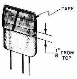
-------- Wrapping the top of a transistor with tape facilitates handling
the component in almost inaccessible areas of small radios.
Hot Penny Removes Tube Socket
I have recently had trouble replacing defective tube sockets on a 1958 automobile hybrid radio. The tube socket pins break very easily especially when inserting tubes with bent pins. In an effort to replace these sockets with an improved type, it is necessary to remove the old socket. Not having the special tools, I imagined that this would be a prodigious job. I tried melting and wiping off excess solder from each pin with a stiff wire brush, according to instructions received at one time.
After carefully melting and wiping off in this manner, I futilely attempted to pry the socket loose and almost cracked the board, but still no luck.
I then placed a copper penny over the seven pins and applied my regular solder gun. The socket almost dropped out by itself.
Keeping Resistors Handy
A neat, space-saving way for keeping an assortment of resistors handy to the service bench is to stretch a length of a discarded coiled heater element between two hooks above the bench. Bend a hook on the end of one lead on each resistor, and hook the resistors along the coil.
The color code will show readily and, if the resistors are arranged in the order of their value, a desired one may be selected quickly.
Shorted Tuning Condensers
Locating shorted plates in ganged tuning condensers may be simplified by using a strip of stiff paper, such as a calling card. Pass the paper successively between the different pairs of rotor and stator plates.
When the shorted plates are separated, the receiver will resume operation.
Transformer Replacement
Considerable labor can be saved when replacing the horizontal output transformer by eliminating the need for disassembling the high voltage cup under the high-voltage rectifier tube and replacing the filament leads on some TV receivers. This can be accomplished by leaving the transformer mounting bracket attached to the chassis and the filament leads attached to the tube socket. Remove the 2 nuts and U bolt holding the core to the bracket. Slip one side of the core out to free the filament winding, then remove the rest of the transformer. Install the new transformer in reverse manner, using original filament winding and transformer bracket.
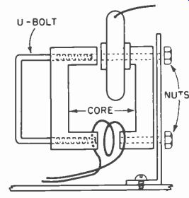
------- Removal of 2 nuts and U-bolt releases filament winding and speeds
flyback replacement.
Tube Kink
A defective 6J5 vertical-output tube located in a 630 chassis, which was in a home about 15 miles from my shop, gave me a hard time because I did not have a replacement or even a poor substitute with me.
What to do? I modified a 6K6 by snipping off part of pin 4 and soldering a jumper from pin 3 to pin 4. This tied the plate and screen together.
Pin 4 was cut just in case the socket connection was used as a tie point.
It worked very well. It saved me a long trip and the customer was happy. I replaced the contraption with a new 6J5 on my next visit to that area.