AC-only receivers
If there should be no reading across the mains lead when checked with an ohmmeter, connect the test prods directly across the set side of the on/off switch, as either it or the lead itself may have gone open circuit. The remedies here are obvious. It is rare for the mains transformer to give trouble unless subjected to gross overloading, so investigate all other possibilities before condemning it. It is worth remarking that a keen sense of smell is as good as a test-meter where transformers are concerned — the odor of a burned-out winding is quite unmistakeable.
Check any fuses with the ohmmeter — don’t trust to appearances. In addition, it is not unknown for a fuse holder in ostensibly perfect order to have developed high resistance contacts, breaking the input circuit even though the fuse itself is all night.
If there is no obvious fuse to test, have a close look at the mains tapping panel, because it often incorporated a small two-pin plug with a fuse in its body. Even where there was no fuse it has been known for these plugs to go open circuit and effectively disconnect the input.
Should all these tests prove negative, and the meter reveal that the transformer primary is indeed open, there is a problem, since replacements are rather expensive if bought new. It may prove to be more practicable to wait until a good second-hand component (perhaps from a similar set) can be obtained. When the work is carried out, first make a careful diagram of the original connections to the transformer including any colour coding for cables, showing the leads to the primary, HT secondary, rectifier heaters, LT secondary, etc. Don’t rely on memory — something unforeseen may delay the job by which time confusion has had time to set in.
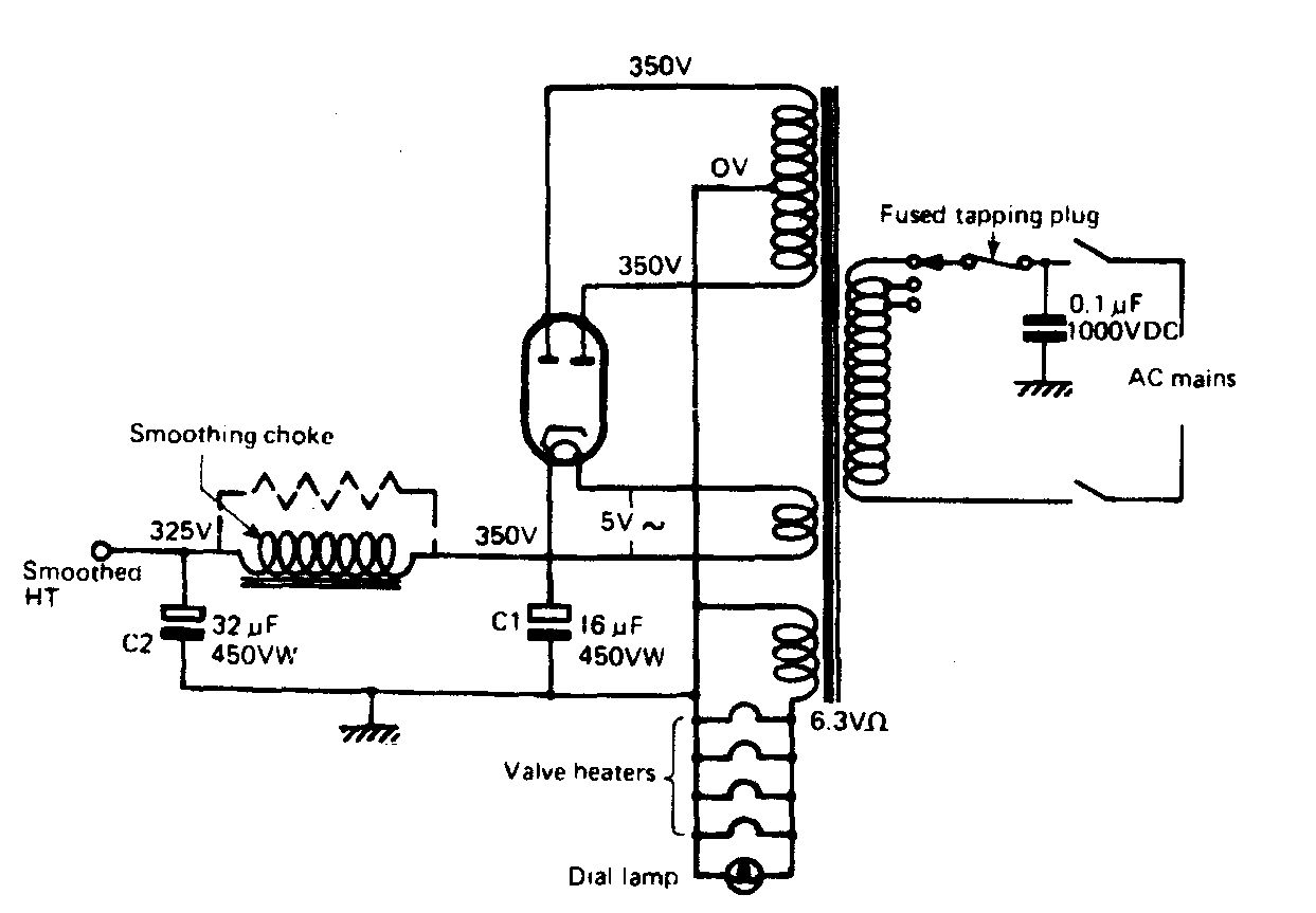
FIG. 1 Typical AC-only power supply unit
If the tube (valve) light up but no HT voltage appears the first step is to replace the rectifier valve. At this stage always test the AC voltage on the anodes of the rectifier valve. It may be anything between 200V and 500V, but the important thing is that it should be the same on both anode pins. Any discrepancy other than a volt or two inevitably points to a faulty mains transformer, which will overheat and destroy itself in time.
If the rectifier shows signs of overheating with reduced output, test for a short on the HT line, initially across C1. Where there is a very low resistance of a few ohms this capacitor is itself suspect, but a reading of up to 1500 ohm indicates that the fault lies on the other side of the smoothing choke or resistor, possibly due to C2 having shorted. The test meter should be transferred to this component, but the procedure is likely to be a little more complicated for this reason. Very often several HT connections will be found on C2. They should be disconnected one by one until the reason for the short is found. This procedure holds good right through the set. If need be, note the connection then unsolder or cut the wire, and test. The most elusive short may be traced in this way, with the exercise of patience — but do be careful to keep those notes!
Low HT volts, with a loud hum from the speaker, points to C1 having gone open circuit or low in capacity. If C2 goes faulty in this way the HT voltage will be normal and the hum not quite so bad.
Use the correct replacements
Proper electrolytic capacitors made especially for the job must be used in HT smoothing circuits, especially in the reservoir position. As has been explained elsewhere, the DC output from a rectifier carries an AC ripple which the reservoir capacitor must be capable of handling. If the HT current drawn by the receiver is, say, 75 mA, the AC ripple current rating of the reservoir must be at least 150 mA. Although the ripple current is not always marked on capacitors, those sold for smoothing purposes will have been designed to handle an ample amount for domestic receivers. When two or more capacitors of the same capacity are housed in a single can, for instance 8 ufd + 8 ufd the section intended to be used in the reservoir position usually will be colour coded red and the section for smoothing coded yellow. It can normally be assumed that when two different values are housed in a can, such as 8 ufd + 16 ufd the smaller value will be intended for the reservoir position.
Miniature electrolytic capacitors are not suitable for use in HT smoothing circuits and should be avoided.
Negative HT smoothing
This is more likely to be found in receivers made in the middle 1930s. Its presence is detected by the fact that the centre tap of the rectifier anode winding is not taken to chassis directly, but via the smoothing choke or speaker field. The reservoir capacitor is connected between the rectifier cathode or filament and the centre tap, making its negative side anything from about 50V to 150V negative with respect to chassis. The point to bear in mind when smoothing capacitors have to be replaced is that the new one may have to be insulated with a few turns of tape to prevent its case (which is usually connected to negative) being earthed by a fixing clip. If this is not done the smoothing choke or/speaker field will be shorted out. If a choke is employed the result will be a powerful hum from the loudspeaker, but if a field is used there will be no sound at all because the loudspeaker will not be energized!
Low voltage negative bias
Some sets have the centre tap of the HT winding returned to chassis via a fairly low resistor, perhaps about 50—100 ohm. This is not negative smoothing but simply a means of obtaining a few negative volts for bias purposes, typically in connection with delayed AVC. The reservoir negative terminal is usually taken to chassis as usual but there may be a fairly large value, low voltage electrolytic connected across the bias resistor. Check this if there is an HT hum not traceable to the main smoothing capacitors.
RF by-pass and other HT decoupling capacitors
Some firms, notably EMI, made a practice of wiring a paper capacitor across the HT line to by pass any KF energy that might appear on it and cause instability. These have been known to go ‘leaky’ or even dead short, taking the HT line down to chassis and causing severe overloading of the power supply stage in general. The value employed was generally from 0.05 ufd to 0.5 ufd and when fitting a replacement use a standard size non-inductive type meant for tubes (valves) radio use.
AC/DC receivers
As with AC sets, the switch should be checked first along with the mains lead, followed by the mains dropping resistor. Since the tube (valve) and dial lamps (if any) are in series, the failure of any one will extinguish all the rest. Dial lamps are more vulnerable than tubes (valves) and should be checked first. Two alternative means of wiring them into the circuit are shown in FIG. 2; (B) is to be preferred. R2 is an optional refinement which allows the set to continue working even if the lamps should fail.
The thermistor also is optional. It is a special resistor having quite a large resistance when cold (commonly 200 ohm) which falls to around 50 ohm when heated by the passage of current through it. It protects the tube (valve) heaters from harmful surges when the set is switched on from cold. Thermistors are robust devices, but they do sometimes crack, or have a connection fail.
If the tube (valve) are lit but there is no HT, try the rectifier. AC/DC types are far more likely to pack up altogether than are AC-only tubes (valves) due to a separate, highly insulated cathode which can be damaged by a short on the HT line. If R1 has gone open circuit and removed the anode volts from the rectifier, check C3, the anti-modulation hum capacitor.
The HT smoothing arrangements are very similar to those of the AC set, but as explained earlier, the voltage is normally equal to, or less than, that of the mains so arrangements are made to get as much of the available voltage as possible in to the anode of the output valve. Very often the HT end of the output transformer is taken directly to the cathode of the rectifier, with a fairly high value resistor (typically 1 k –ohm-5 k-ohm) used to ‘smooth’ the HT to the rest of the set. Check this resistor for damage from overheating. In the odd cases when the output transformer has an overwind for HT smoothing and this has gone o/c a conventional transformer may be used as a replacement, ignoring the overwind and taking the HT end of the primary to rectifier cathode.
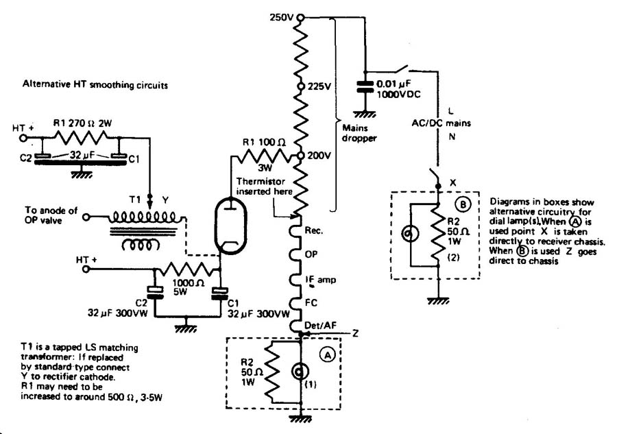
FIG. 2
Tracing HT shorts should be carried out as described for AC-only receivers.
When the mains dropper fails
Open circuits on mains droppers may be treated in two ways, according to the extent of the damage. When only one section of a multi-tapped resistor has gone it is worth checking to see if a slight rearrangement of the connections will put things right. For instance, with UK mains now standardized at 230 V any windings fitted exclusively for 240V and 250V may be adapted for other purposes. Otherwise, it is often possible to wire a replacement resistor across an o/c section to take its place. Connections here must be good and firm: use high melting point solder or nut-and-bolt joints.
Should the entire mains dropper be open circuit, all is not lost, even if the resistance value is unknown. Once the total voltage required by the tube (valve) and dial lamps is established, the correct resistance can be calculated by Ohm’s law.
A typical tubes (valves) line-up would be UCH42, UF41, UBC41, UL41 and UY4I. The voltages of the heaters are, in order, 14V, 12.6V, 14V, 45 V and 31V, a total of 116.6V. Two dial lamps of 6.3V each would bring this up to a shade under 130 V. Thus the dropper would have to make up the difference between 130V and the 230V mains. Referring again to FIG. 2, it will be noted that not only the heater current, but also the HT current, flows through the top part of the dropper. This must be taken into account when calculating. According to the data, the current under average working conditions is in round figures 70 mA. Added to the heater current of 100 mA, the total flow through R1 and R2 in FIG. 2 will be 0.17 A. Each resistor will be required to drop 20V at the given current so Ohm’s law gives us just under 118 ohm. The nearest commercial value of 120f ohms should be used. The wattage is given by 20V X 0.17A = 3.4W, so a 5W type will be well within its rating.
Moving on to R3, we find that this has to drop the remaining 70V (200 V minus 130V) at the heater current of 0.1 A. This works out to a convenient 700 ohms at 7W, and a suitable resistor should easily be obtainable. R4 is called a limiting resistor, and its purpose is to damp any surge of current through the rectifier when the set is first switched on from cold. A 100 ohm, 3W resistor makes a very good replacement.
Part AC-only sets
Generally speaking the power supply sections of these sets follow the same lines as those of AC/DC receivers apart from the use of an auto-transformer in place of a mains dropper and the same fault finding and repair techniques apply.
Experience has shown that the auto-trans formers used in these sets are extremely robust and unlikely to fail in normal use. However, if this does happen consideration should be given to converting the set to full AC/DC operation by replacing the transformer with a mains dropper.
Resistive mains cords
These were used in many small and midget AC/DC receivers, both UK made and imported (especially from the USA) from about 1933 to 1953 as an alternative to a normal mains dropper. Unfortunately replacement cords have not been made for very many years so the chances of finding spare lengths are very slim. Some old stocks may have survived in long-established radio shops but even then they may not be in usable condition. When resistive cords are left rolled up for years on end there is a tendency for o/cs to occur at short intervals along their length, rendering the whole thing useless, so if you do find a ‘new’ coil of line cord check it carefully. You might find some odd straight lengths that may happen to be of the correct resistance value but as this would fall into the category of a near miracle some more down- to-earth possibilities need to be examined.
Your course of action will depend to a large extent on the exact job done by the cord in a particular model. Most UK-built receivers were made to work with HT lines of around 200V, the least voltage that might be expected from the 200/250 V mains, so the rectifier anode was sup plied almost directly from the mains and the resistive cord had only to handle the heater current. In this case it may be possible to route a new conventional mains lead into the set via a voltage dropping device for the heaters, such as an auto-transformer, a mains dropper in a metal safety cage or simply a mains electric light bulb of suitable wattage. Note: this will always be higher than would at first appear likely to take account of the lower current the lamp will pass when in series with the heater chain. For instance, a 230V 100W lamp will pass about 0.43 A in normal service but will be very suitable for a 0.3 A chain. For 0.2 A chains use a 60W lamp, and this size probably will be suitable also for 0.16A and 0.15A chains because these are likely to add up to a much higher voltage than 0.2 A types. Finally, for 0.1 A chains try a 40W lamp.
Extra precautions necessary with AC/DC and part AC sets
It was common practice to use only a single-pole mains switch to break the side of the mains lead that went to the HT-line and the bottom of the heater chain, which in almost every known British set was the chassis of the receiver. The interesting situation arises that if the mains lead is plugged in to make the chassis neutral while the set is working, it will become live when switched off and vice versa, due to the path from the top of the heater chain back down to chassis. It is therefore essential to replace most carefully all the various devices such as covers for chassis and grub screws employed to prevent owners from accidentally coming into contact with live metalwork. It is also worth considering replacing the existing mains switch with a double-pole type which will break both sides of the mains input.
Note: it is not possible to switch all the conductors in a three-core resistive line cord, so always either switch off at the mains socket used to supply such sets or withdraw the plug.
Barretters
In place of a mains dropper, certain AC/DC and DC-only sets had a device known as a barretter. This resembled an old-fashioned light bulb, and used a principle which had been discovered many years ago, namely that a resistance wire made of iron enclosed in a hydrogen atmosphere tends to pass the same amount of current within quite wide variations of applied voltage. This is, of course, ideal for regulating the current through a series heater chain, especially where the mains voltage is subject to severe fluctuation. Barretters were made at one time or another to suit virtually any range of tubes (valves) drawing between 0.1 A and 0.3 A. The type of base varied widely according to type. Some had an Edison screw as used for US light bulbs, others had valve-type bases matching those employed in the receiver.
In the event of a barretter failure it is worth while making enquiries of the various vintage tubes (valves) specialists, because there is a very good chance of obtaining an exact or near-equivalent replacement. Otherwise, give consideration to the use of an ordinary electric lamp, as discussed earlier.
American radios often had special barretters or ‘ballast’ tubes incorporating shunt resistors for pilot lamps. Either glass or metal/glass envelopes were fitted, and the bases were either UX 4-pin or octal.
Comprehensive lists of both British and American barretters will be found in Google.
‘Watt-less’ droppers
Ever since the 1940s radio magazines have been talking about using large value paper capacitors in place of a conventional droppers in series-heater receivers, on the grounds that the capacitor consumes no power, produces no heat, cannot possibly go wrong and generally is just about the best thing since sliced bread. The fact remains that the idea was never adopted commercially except in one particularly horrible little television set which gave so much trouble that it had to be recalled for modification to a conventional dropper. However, for anyone keen to try the method, as an example, a dropper for a typical 0.15 A range of tubes (valves) operating from 230 V mains would be about 800 ft. A 4 ufd capacitor has a reactance of 796 ohm at 50 Hz and could thus be used as an alternative to a dropper or barretter or even an auto-transformer. Remember though, that all these are fail-safe — if they stop working it is because they go open circuit, preventing any voltage from reaching the heater chain. On the contrary, when a capacitor working under these conditions fails it is almost certain to go dead short and expose the chain to a catastrophic overload in which the tube (valve) are bound to suffer damage —Murphy’s Law.
Replacing ‘metal’ HT rectifiers
This term includes every type from the original old finned copper-oxide types to the later contact cooled models. They all shared a common characteristic of having a fairly high forward resistance, which means that they had an inherent current- limiting action so that when a set is first switched on there is a certain restriction on the output voltage and current. They were also all prey to the effect of falling output with age, and it is all too common to find that the HT in a set using a metal rectifier has dropped to half the normal figure. In such cases it is tempting simply to fit as a replacement a miniature silicon rectifier which produces no heat, cannot possibly go wrong and — well, you know the rest.
In fact, silicon rectifiers, good as they admittedly are, are not suited technically for use in vintage radio sets without special precautions being taken. They have an extremely low forward resistance which means that (1) heavy peak currents flow at initial switch-on and (2) the DC output is very likely to be equivalent to the peak value of the AC input. With (1), when a silicon diode is fed from a mains transformer the initial surge is capable of causing overload damage to the latter, while with (2) the voltage on the HT line may rise so much above the design rating as to cause component or even tubes (valves) failure.
To examine a typical case, consider an AC/DC receiver in which the original metal rectifier was fed with AC directly from the mains input. Its output would have been expected to be the equivalent DC voltage, say 230 V, and the ratings of the smoothing and other capacitors will have been designed to suit this voltage. A silicon rectifier used as a replacement might well produce a DC output of towards 100V more than that of the AC input so the potential danger of over loading is quite evident. This is of particular importance in mains/battery sets such as the Ultra ‘Twin’ series in which a small metal rectifier produced both the HT voltage and the LT for the tube (valve) filaments; an ill-judged replacement with a silicon rectifier could easily cause one or more of those filaments to burn out expensively.
The answer is to fit a suitable limiting resistor between the AC input and the anode of the silicon rectifier. A certain amount of experimentation may be needed to find the exact value required, starting with something likely to be on the high side for safety. In the Ultra ‘Twin’ the output from the original rectifier was measured for the service data as 223 V DC with an AC input of 230 V. The HT current consumption was 10 mA and the filaments drew 47 mA. Since a silicon rectifier may be expected to deliver well over 300 V DC, the limiter should initially be capable of dropping 100V @ 57 mA (i.e. the combined HT and LT current). For this a 2.2 k wire-wound rated at 5 W would be suitable. Check the DC output under working conditions and if necessary reduce the value of the limiting resistor a little at a time until the correct output voltage and current are measured. Note: in mains/battery receivers the usual practice was to run 1.4 V rated filaments at 1.3 V for longevity and to give a margin of protection against voltage surges. On no account should this voltage be exceeded in service.
A few very early AC-only mains receivers used metal rectifiers in voltage-doubling circuits which also must be treated with care when silicon diodes are to be used as replacements. It would be better to use a separate limiting resistor for each rectifier rather than a common one which might run too hot for comfort. Again work on the basis of starting with large values and reducing them if necessary until the correct output voltage is obtained. The same remarks apply to the replacement of bridge rectifiers such as the contact-cooled types used in receivers of the late 1950s.
Dealing with energized loudspeakers
The general design of these has been touched on in an earlier section. When the field winding is used in place of, or to augment, a smoothing choke for the HT supply of the receiver a failure of the winding obviously will stop the set dead. If a replacement speaker is not available consider substituting an LF choke or even a large resistor for the field and replacing the loudspeaker itself by a permanent magnet type. The DC resistance of the smoothing choke or resistor should match that of the old field winding so that the HT voltage remains correct. When a smoothing resistor is employed it should be mounted on an insulated tag strip in a place where it will receive some ventilation.
Conversely, if an energized speaker has suffered irreparable cone damage but the field winding is still in good order, it may be possible to remove the latter (complete, not just the winding) and to mount it, say, on the baffle board with wood screws where it can continue to do its job of smoothing the HT. A permanent magnet speaker may then be used without further modification being required.
A few sets, notably some American ‘midgets’, had energized speakers whose field windings were connected between HT and earth, being used as pure electromagnets. These speakers may be replaced by permanent magnet types without any bother, except that the HT should be measured to ensure that with a reduced load it does not become too high. In most midgets 90 V is quite sufficient, and above this the output tubes (valves) tend to dissipate more power than is good for them. An extra series resistor in the rectifier anode circuit is the best way to deal with this situation. Incidentally, it was not unknown for the speakers in these sets to be of the high impedance moving-iron type, and this should be checked if an output transformer is not immediately visible.
Note: whenever faults are found in a power supply unit that are the result of overloading, always check the coupling capacitor feeding the grid of the output tubes (valves) — see next section.