The tube (valve) used in the IF amplifiers of the very early superhets were ‘straight’ screen grids, but these were soon replaced by variable-mu types and then by RF pentodes. In all cases complete failure of the amplifier can be brought about by a screen-grid HT supply resistor going open circuit. In some cases a single resistor was used to supply either two IF amplifiers or a single IF amplifier and the frequency changer, the current passed being high enough to warrant the use of a wire-wound type. Always check these for signs of overheating. Some firms, notably EMI, slipped sleeving over such resistors, in which case look for signs of its having become brittle with heat. Any overloading may be due to leakage on an associated decoupling capacitor.
A common practice in the early 1930s was to seal most of the paper capacitors used in a set within a pitch-filled metal box sprouting a dozen or more soldering tags for connection purposes. Unfortunately, as so often happens to inaccessible components, these capacitors go ‘leaky’ and draw heavy current through the feed resistors. The easiest cure is to snip off the leads from the sealed box and to fit a replacement modern capacitor close to the tube (valve) holder. Whilst this works perfectly well, some purists are moved to take out the boxes, melt out the pitch and fit new capacitors in place of the old, subsequently re pitching the box and fitting it back as before. The writer leaves it to the individual to decide whether or not to go to this length, but if you do for goodness’ sake make a very detailed diagram of the connections before you start!
Cathode bias resistors seldom give trouble, nor for that matter do their decoupling capacitors. Although the latter have as much chance of going leaky as any other elderly capacitor, it really doesn’t matter very much as long as the capacity is unaffected. A leak of 50k-ohm on a screen grid decoupler could cause problems, but on a cathode decoupler connected in parallel with a resistor of only about 300-ohm maximum it is immaterial.
Deathly silence
Occasionally you may encounter self-oscillation in the IF stage. It is difficult to describe the effect of this except as a most unnatural silence which can almost be ‘heard’. This is due to two things: first the grid of the IF tubes (valves) is driven heavily negative by the oscillation and secondly the latter causes a large AVC bias to be developed. A strange concomitant is that the voltage as measured on the anode of the IF tubes (valves) will be very considerably higher than that of the HT line itself! The most likely cause is an 0/c screen decoupling capacitor.
Another source of self-oscillation
The majority of British screen grids and RF pentodes were made with ‘metallized’ envelopes, a thin layer of metal being sprayed onto the glass and connected down to cathode or a separate earth pin on the base. The metal screen thus provided protected the tube (valve) from mutual interaction with its nearby neighbors or other components. Some makes of tubes (valves), especially MOV, were prone to losing chunks of the metalizing over the years, to the detriment of the screening effect, resulting in IF instability. It may be possible to effect a cure by wrapping a layer of metal cooking foil tightly around the tube (valve) and earthing same to the original metalizing connection. This took the form of a thin wire sprouting up from the tube (valve) base and glued onto the metalizing with the aid of a thin washer. With some other makes of tubes (valves) the metalizing tended to stay intact but the earth connector came loose. The old engineers’ trick is to wind a number of turns of thin fuse wire around the metalizing near the top of the tube (valve) base and then solder them to the connecting wire. This simple trick can effect a wonderfully efficient repair and enhance an engineer’s reputation out of all proportion to the deed.
Beware
Many of the octal-based RF pentodes and ‘kinkless tetrodes’ made by M-OV were made without metalizing and metal screening were fitted with cans by the set-makers using them, chiefly EMI and GEC. This left a ‘spare’ tag on the tube (valve) holder which very often was used as an HT anchoring point. An electrically equivalent metallized tubes (valves) should never be substituted for the original in one of these sets as the metalizing will become connected to HT+ and therefore 200V DC or more above chassis.
Repairing faulty or damaged IF transformers
IF transformers fall into two main groups, those having fixed inductance coils trimmed by small variable capacitors, and those having adjustable iron-dust cored coils with parallel fixed capacitors. It has been known for the latter to change capacity with age, de-tuning the transformers and making it impossible to bring them back to correct alignment. In this respect be especially vigilant for small disc-like capacitors about the size and shape of a pajama coat button; these had silvered-mica elements which tended to crack. Replacements should be of the close-tolerance type. Sometimes the originals have odd values and it may be necessary to use two new ones in parallel to obtain these. If you can’t get the exact value, a pfd or two either way shouldn’t matter since the adjustment of the core should make up for this.
Trimmer capacitors were usually fitted with thin slices of mica to act as a dielectric. It is a brittle material which can and will break up under rough treatment, so take care if you need to adjust them (but see the later remarks on realignment before touching them!).
It is inevitable that at some time an IF trans former will be encountered which has suffered damage at the hands of an unskilled person. The most common victims are those with iron-dust cores, for these are easily damaged if an attempt has been made to adjust them with an ordinary screwdriver, a tool quite unsuited to the job. The result is all too often a core which is split and jammed in the coil former. There is a remedy, but it calls for a steady hand and much patience. The broken core must be drilled out with a fine drill, used in a hand brace, until only a shell remains. Extreme care must be used, as any deviation from a straight line will be likely to ruin the former and probably the winding as well. The remains of the core are then broken out little by little with the aid of a slim screwdriver.
When every last scrap has been removed the thread may be cleaned up by running a suitable size of bolt through its length. Replacement cores may be obtained as kits, or salvaged from scrap radio or TV sets. Smear them with silicone grease before fitting, and run them through the formers, end to end, using only light pressure and reversing the direction as required to pass any tight places. It is imperative that the tool used to turn cores fits the slot perfectly. It must not be a loose fit, or the slight to and fro movement will soon wear a slot into a useless hollow. Incidentally, many cores are double-ended, and one which has worn away at one end may still be usable if it can be eased out and reversed.
The time-honored method of making trimming tools among radio engineers is to obtain a hard (but non-metallic) knitting needle of the appropriate thickness and to shape it to fit the slot with a file or sandpaper. If the needle is brittle, so much the better, for the chances are that it will break before a core if the latter sticks. Later cores were of smaller dimensions than the original pre-war types, and some will be found to have hollow centers, either still slot shaped, or of hexagonal section. Tools to fit these may be obtained from component firms who advertise in such journals as Practical Wireless and The Radiophile.
It was common practice for manufacturers to seal cores after factory alignment to prevent movement in transit. Some used wax, others quick drying paint. Another method was to insert a piece of wool or thin rubber in the former to exert a gentle pressure on the core. Wax may be softened with a soldering iron, which should be applied for just enough time for the wax to start to melt, but no longer, or it could run down the threads and set again quickly. The core should be unscrewed whilst the wax is still soft, then both it and the former can be cleaned up properly. The kind of paint usually employed was a cellulose-based varnish, which will respond readily to a few drops of nail varnish removing fluid. As to how you more different ones across the required bandwidth. These may be identified in the IF data in Appendix 1 by groups of figures separated by dashes, e.g. 128.8—122.8—126.5—122.5 (the actual set is the Marconiphone Model 535). In this case, the first IF winding, that in the anode circuit of the frequency changer, is peaked at 128.8 kHz, the second winding, in the grid of the IF amplifier, is peaked at 122.8 kHz and so on. It is even more essential that ‘staggered’ IFTs should be adjusted and readjusted extremely carefully than with conventional IFTs.
Do not forget to remove the short on the local oscillator after the IF alignment is completed.
Aligning with a wobbulator and oscilloscope
This method has already been outlined in the section on instruments. In practice the output from the wobbulator is connected in the same way as a conventional signal generator and the input to the oscilloscope is connected between chassis and the diode load resistor near to the last IF trans former. The terminal on the wobbulator marked ‘X’ should be connected to that marked ‘X Plate’ or ‘X Plate Direct’ on the ‘scope. This synchronizes the two instruments and ensures a steady response curve on the latter.
The tuning control on the wobbulator is set for the nominal IF and the ‘sweep bandwidth’ control to about 25 kHz. The resulting response curve on the screen of the ‘scope should be something like that shown in FIG. 1 — but don’t be surprised it is anything but to start with. Adjust the trimmers or cores in sequence, a little at a time until the curve begins to come into shape and eventually approaches the optimum. It may not be possible in practice to attain an exactly symmetrical shape, but this is not so important as the avoidance of steps in
the sides, or nearby spurious peaks, which would bring about co-channel interference when the set was tuned to one of a group of closely spaced stations. Note that the top of the curve should be flattened off to give a sensibly even response over about 2 kHz above and below the nominal IF, and that it then falls away fairly steeply. This is a good compromise shape for a domestic receiver where reasonable selectivity has to be balanced against adequate bandwidth, to preserve the higher AFs.
Alternative IFs
When consulting the list of IFs in Appendix 1 you may find that occasionally more than one figure is quoted, such as ‘128 or 134’ (Cossor Models 634 and 635). The reason for this is to do with our old friend the image frequency, with its relationship between the IF and certain transmitter wavelengths. It was found that a slight change of IF was beneficial in certain areas of the country, the particular firm’s dealers in those parts being instructed to realign the sets as required. After sixty or more years the original need for the particular IF probably will have gone, but it is as well to keep to the one chosen for the set, because if this is altered all the RF and local oscillator alignment will have to be readjusted as well.
Beware of HT!
A final word of warning regarding transformers fitted with trimmer capacitors. These may need to be adjusted with a metal tool due to stiffness and if this proves necessary, take care, for trimmers across the primary windings will be at HT, normally 200 V and more in mains sets. Insulate all but the tip of the tool to prevent shocks or shorts.
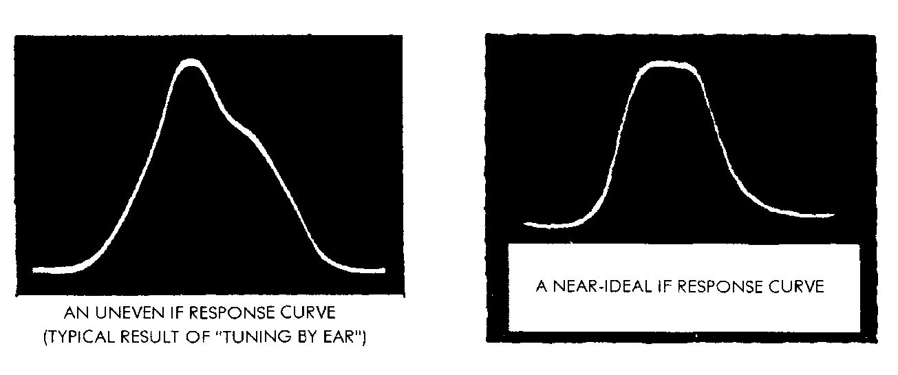
FIG. 1 -- AN UNEVEN IF RESPONSE CURVE (TYPICAL RESULT OF TUNING EY EAR)