The use of microphones and loudspeakers to address public gatherings was pioneered in the early 1920s and rapidly became widespread, especially as more powerful output tubes (valves) and loud speakers became available. When nowadays young people talk casually of 160W amplifiers in motor cars, it is interesting to look at the output powers considered suitable in the tube (valve) era, when watts really meant watts and was not a meaningless tag. Around 1930 a guide published on the work of wiring cinemas for talking pictures stated that between 3 W and 5 W was perfectly sufficient for medium to large halls, in conjunction with very efficient giant horn loudspeakers. Even then some patrons complained that the sound was too loud! Twenty years later 25 W was considered adequate for most general purpose PAs and in the early 1960s the present writer installed a complete 25-loudspeaker music system in a noisy factory using an amplifier with this output rating.
The term ‘high fidelity’ (usually abbreviated to ‘hi-fi’) came into use in the 1930s, when attention was being turned to amplifiers and loudspeakers that should reproduce speech and music, especially the latter, with as much faithfulness as possible to the original sounds. The amplifier is, of course, only a link in the chain between the sound, a microphone and a broadcast or gramophone record. As we have seen earlier, the frequency range of AM broadcasting was necessarily restricted in accordance with the channel spacing of transmitters, and well-recorded 78 r.p.m. records, with a range of between 50 Hz and 8000 Hz could comfortably provide better sound quality when reproduced properly. This superiority was extended further when the Decca Record Co. introduced its ‘FFRR’ (Full Frequency Range Recording) system in 1947, making it possible for 78s to reproduce from 20 Hz to 15 000 Hz. To complement the records Decca introduced new magnetic pick-ups with similarly extended frequency response and some excellent radio-gramophones and record players. When long playing (LP) records arrived a few years later the upper frequency response was enhanced still further, calling for even better pick-ups and amplifiers. Throughout the late 1940s and 1950s many well-known designers and manufactures produced a succession of continually improved amplifiers, although it must be said once the question of providing adequate frequency response had been settled much of the claimed advances lay in the reduction of distortion. This was carried to the point where improvements were being claimed in fractional percentage figures which makes it doubtful if even a highly trained musician could have told the difference. In fact, it used jokingly to be suggested that many hi-fi buffs spent more time listening for faults that in enjoying the music or song provided by records!
As regards output powers, G.A. Briggs, a leading authority on sound reproduction, observed that in most domestic listening conditions no more than 0.25 W was required, but amplifiers needed to have a much greater reserve power to preclude distortion on very loud passages of music. Ten watts maximum would have been considered more than adequate.
Design features
The design of PA and hi-fi amplifiers follows similar lines, bearing in mind that the former do not need to have as wide a frequency response as the latter, the circuitry of which is likely to be somewhat more complex. Designing amplifiers is an exceedingly involved subject, involving as it does considerations of such things as harmonic and intermodulation distortion and of different classes of operation such as Classes A1 and A2, and AB1 and AB2. In quoting examples we shall confine ourselves to designs using what are almost certainly the best known and most popular output tubes (valves), the PX4 and PX25 directly heated power triodes and the KT66 beam-tetrode. The first two date from the late 1930s and the third from 1938, and all remain extremely desirable today, it being not unusual to see good second-hand pairs of these tubes (valves) changing hands at between $70 and $220.
Output powers
The PX4 is capable of giving up to 13.5W in Class A push-pull with an anode voltage of 300V, this being more than adequate for domestic purposes. The distortion at maximum output is 2.5%, and is proportionally lower at less output. If the anode voltage is reduced to 250V the maximum output is 9W with a distortion of 2%. Both these outputs are achieved with virtual cathode biasing via separate centre-tapped heater windings for each PX4.
A pair of PX25s Class A will give 15.5W with an anode voltage of 400 V or 20W with 500 V applied. The respective distortion figures are 2.5% and 2%; note that the figure is smaller for the larger output. This is achieved with virtual cathode biasing. If fixed bias is employed and the tube (valve) operated in Class AB1 with fixed grid bias the output with 525V nominal on the anodes is raised to 26W, at the cost of slightly more distortion — 14%.
The KT66 is capable of giving much greater power outputs than the PX25 but with somewhat higher distortion figures. For instance, in Class A push-pull with cathode bias and 250V on the anodes, a pair will give 17W, with a distortion of 4%. At 390V on the anodes the power is raised to no less than 30W, with 6% distortion. The use of Class AB1 with fixed grid bias and a nominal HT of 510 V the power rises still further to 50W, with a better distortion figure of 5%.
The high power applications of the KT66 are largely confined to PA amplifiers. For hi-fi work the tube (valve) may be connected as triodes (anode strapped to screen grid) to give less distortion although at much reduced power. In Class A with cathode bias and 250V on the anode, a pair will give 4.5W with a distortion of 2%. Raising the anode voltage to 400 V results in an output of 14.5W with 3.5% distortion.
The Osram PX4 push-pull amplifier ( FIG. 1)
The first tubes (valves) (L63) operates as a ‘concertina’ phase splitter. As both the 10000 ohm anode feed resistor and 1000 ohm cathode bias resistor are by-passed the respective load resistors, both 2000 ohm are balanced. The anti-phase signals are fed to the grids of two more triodes operating as conventional amplifiers and used to drive the output tubes (valves) by choke- capacity coupling; note the use of a centre-tapped choke. There are 10000 ohm stoppers in each PX4 grid and 100 ohm stoppers in each anode. Each PX4 has its own heater winding on the mains transformer, center tapped to return to chassis via a 1000 ohm bias resistor by-passed by a 50 uF capacitor.
The Osram PX25 (Class A) amplifier ( FIG. 2)
Only the output stage is shown, with the tube (valve) driven by the centre-tapped secondary of a trans former the primary of which is in the anode circuit of a preceding driver valve, typically another L63. Ten thousand ohms grid stoppers are again fitted but the anode stoppers are omitted. Virtual cathode bias is again employed with centre-tapped heater windings for each PX25.
The Osram PX25 (Class AB1) amplifier
The driver tubes (valves) (L63) again works into a trans former, this time with two separate secondary windings for the PX25 grids. This enables the negative grid bias to be applied individually and to be balanced by the two 50000 ohm potentiometers shown below the lower PX25. In the initial setting- up procedure each PX25 would be tried on its own and the bias altered until each drew the same anode current. Note the D41 double-diode shunted across the grid circuits of the two PX25s. This unusual feature is intended to provide a low impedance path to earth should potentially harmful positive voltages appear on the grids, and it is not likely to be encountered in commercial amplifiers. The negative bias voltage is obtained from a tapping on one side of the main HT winding on the mains transformer, taken to a half-wave rectifier working ‘backwards’ with the output taken from its anode to provide —70 V after smoothing by a 50 000 resistor and two 0.1 uF capacitors.
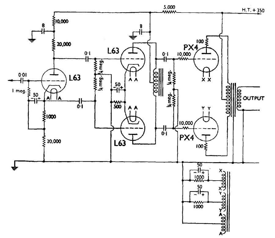
FIG. 1 The circuit of an amplifier using PX4s in push-pull
Note that the HT smoothing uses a ‘swinging’ choke, which helps to stabilize the output voltage. The 20000 uf bleed resistor connected from HT+ to chassis maintains a necessary minimum current through the choke.
The Williamson KT66 amplifier ( FIG. 3)
The Williamson amplifier was conceived especially to take advantage of the new ffrr records, and its performance shows how that aim was fully realised. Negative feedback from the secondary of the output transformer to the cathode of V1 helps the achievement of a very nearly constant frequency response from 10 Hz to 20000 Hz.
The first AF amplifier tubes (valves) (V1, L63) is directly coupled to the concertina phase splitter (V2, L63), the anode of the first being connected to the grid of the second. In normal circum stances the presence of the 100 V anode voltage of Vi on the grid of V2 would destroy it, but due to its operation with a large value cathode load resistor (R5, 22000 the cathode voltage is 105 V, so the grid is actually at —5 V with respect to it. Anti-phase outputs from V2 are coupled via 0.05 uF capacitors to the grids of the two driver triodes (V3, V4, L63). These in turn are resistance-capacity coupled to the grids of the two output tubes (valves) (V5, V6, KT66), and the inclusion of the potentiometer (Ri2, 25 000 ) between the two anode load resistors for V3 and V4 enables very accurate balancing of the drive voltages. Used in conjunction with the potentiometer (R17, 100 and variable resistor (R21, 100 ohm) in the common cathode circuit of V5 and V6 extremely good overall balance of the output stage may be achieved.
It will be seen that V5 and V6 are operated as triodes by having their screen grids and anodes strapped via 100 ohm resistors. Used in this manner they produce some 15W of output power at very low distortion.
Had the KT66s been operated as beam tetrodes the output power of this amplifier easily could have been doubled at the price of somewhat reduced frequency response and a higher percentage of distortion, neither of which would have been of great significance for PA work.
Preamplifiers ( FIG. 4)
It was usual for a hi-fi amplifier to be fed from a discrete pre amplifier incorporating facilities for tone control and for switching in different signal sources. There might, in addition be high or low note filters and the means of compensating for the different kinds of recording techniques used for 78 and LP records, British and American. General duty PA amplifiers usually had a built-in pre amplifier which included simplified tone controls and ‘mixing’ facilities whereby inputs from say, a microphone and a gramophone pick-up might be faded in and out as required.
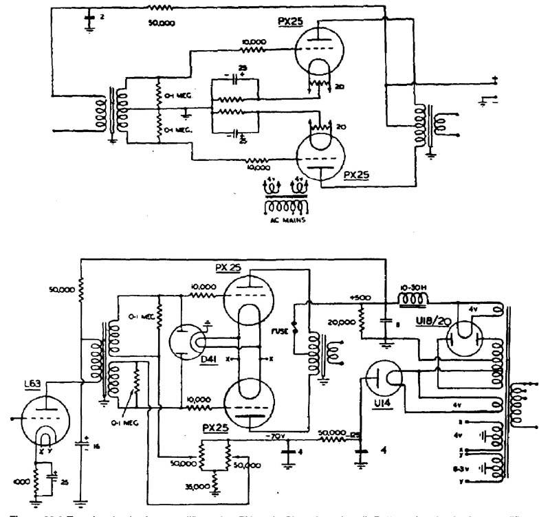
FIG. 2 Top: the circuit of an amplifier using PX25s in Class A push-pull.
Bottom: the circuit of an amplifier using PX25s in Class AB1 push-pull. Note
the separate rectifier used to provide negative grid bias.
A very well-known manufacturer of hi-fi amplifiers once remarked that he built his equipment to have a flat frequency response over a very wide range and that technically speaking no tone controls were either necessary or desirable, but he had to include them because the public demanded them. This is a very valid point which must have struck other designers but nevertheless all hi-fi preamplifiers incorporate some kind of treble and bass cut or boost controls, many of them being based on original designs by P. Baxandall.
A good example of a commercial preamplifier is provided by the Pye model PF91A (1955), which used two ECC4O double-triodes. Inputs were provided for a microphone, crystal or magnetic pick-up cartridges and inputs from a radio unit or a reel-to-reel tape recorder. The first tubes (valves) (V1A) acted as a straight amplifier, but its output was coupled to the second tubes (valves) (V1B) via an ‘equalization’ network which modified the response to suit the different inputs.
The output from V1B was resistance-capacity coupled to a third triode (V2A) via treble and bass controls which could modify the response to each over wide limits. V2A’s output was again RCC coupled into a switched filter unit which could limit the overall high note response to 4 kHz, 7 kHz or 12 khz (a fourth switch position cut out the filters completely).
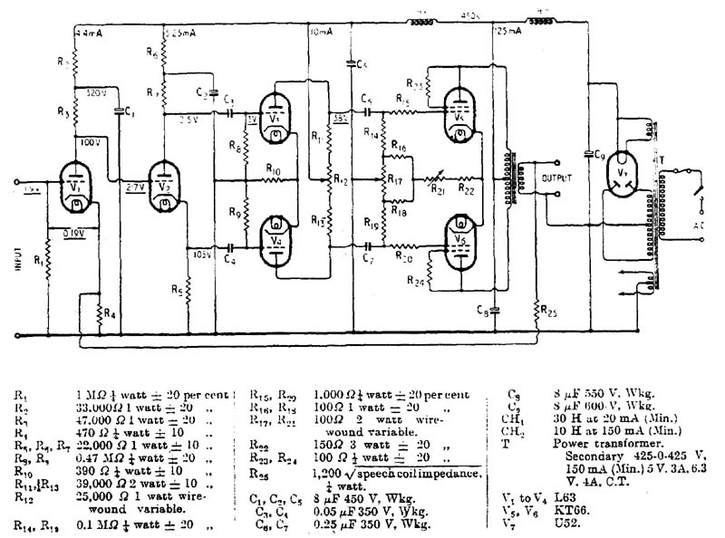
FIG. 3 The circuit and component values of the Williamson amplifier. (Reproduced
by courtesy of Wireless World)
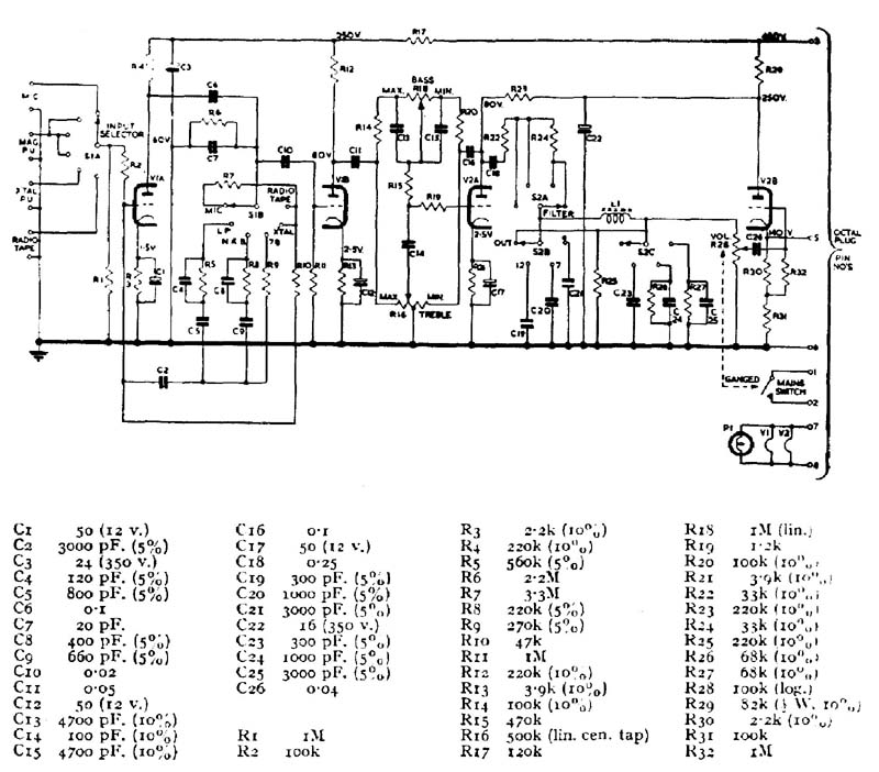
FIG. 4 Top: the circuit of the Pye PF91A preamplifier. Bottom: the capacitor
and resistor values
The output from the filter unit was taken to the grid of the fourth tubes (valves) (V2B) which was operated as what is called a cathode follower. In this the anode is taken directly to HT and the output obtained from a load resistor in the cathode circuit. This results in 100% negative feedback being applied to the stage, endowing it with excellent frequency response with very low distortion. In addition the input impedance is high and the output impedance low, making it useful for working into a main amplifier via long connecting cables which otherwise might be susceptible to hum pick-up. The price for all these advantages is a stage gain of less than unit — typically 0.9 — but this is of no importance when the preceding stages have an abundance of gain.
Incidentally, Pye’s advertised claim for the PF91A and its associated PF91 main amplifier (which used KT66s strapped as triodes) was an output of 12W with less than 0.1% distortion at 1000 Hz, and with an overall frequency response of between 2 Hz and no less than 160 kHz! Although, of course, far beyond the upper limit of audible sound, the very high treble response was considered to be valuable for the correct reproduction of transients in music.
Repairing amplifiers
Fortunately the technical niceties of amplifiers are academic as far as repair work is concerned because it only involves the original designer. All you need to remember is that amplifiers are only extended version of the output stages used in radio receivers, the servicing of which we have discussed. As with radio receivers the majority of faults will be found to be due to leaky capacitors, abnormally high resistors and bad previous repair work. There is absolutely no need to fear that amplifiers must be difficult to repair, provided they are tackled logically, stage by stage in the manner already advocated in this guide, with the knowledge of what the various tubes (valves) electrode and other voltages ought to be. At this point it must be mentioned that we ought to differentiate between grid bias provided by resistors in the cathode circuit of the tube (valve) and that provided by a source of negative bias, so from now on we shall refer to the first as cathode bias and only to the second as grid bias.
It is usual for there to be at least two stages preceding the output stage to provide initial amplification of signal from gramophone pick-up or radio and then to act as a phase splitter to drive the output tubes (valves). There may, however, be several tubes (valves) in each of those stages, especially in high power amplifiers where the output tubes (valves) require a considerable amount of signal voltage to drive them. In many cases the main amplifier is itself preceded by a ‘preamplifier’ which as well as building up the signals also provides for the switching in of different inputs and for controlling the tone. We shall look at these units later, after we have examined main amplifiers.
Power supply sections
These follow the same lines as for radio receivers except that the HT voltages involved are likely to be considerably higher. Whilst some small power amplifiers may manage with an HT line of 300 V, larger units may well have lines of 400 V or even more. The amount of anode current drawn by the output tubes (valves) in the bigger amplifier also is higher, with the HT winding on the mains transformer and the rectifier commonly being capable of supplying 250 mA. Choke-capacity smoothing is the norm although you may occasionally encounter the swinging choke method. More often than not there will be several stages of smoothing providing different levels of voltage for the various tubes (valves) stages. Older high power amplifiers often employed large paper capacitors with working voltages of around 600V in the reservoir and first smoothing positions; it is not unusual to find these still in perfect order after fifty and more years of use.
On the LT side there will usually be more windings than are found in ordinary radio mains transformers. When the PX4 (4 V @ 1 A) and PX25 (4 V @ 2 A) are used in the output stage each may have its own filament supply with one or more 6.3 V windings for the other tubes (valves). KT66s require 6.3V @ 1.27A each, usually supplied by a single winding but with one or more others to supply the other tubes (valves). A large rectifier such as the U52 draws 2.25 A @ 5 V. so the overall heater wattage of an amplifier may well amount to 40 W. With the HT supply wattage easily reaching 100W, the mains transformer is likely to be vary large and very expensive to replace. It thus behoves you to take extra special care to ensure that such items as grid coupling capacitors are changed at the least sign of leakage.
HT fuses
To their credit, many amplifier makers fitted a fuse in the return circuit of the HT winding centre tap to HT—. In the event of heavy HT current being drawn this offers far better protection to the HT winding than does a fuse in the mains transformer primary, which may not blow until the winding has been irreparably damaged. You are strongly recommended to install an HT fuse if none is already fitted. Use a ‘quick-blow’ fuse which will blow long before there is a chance of the winding being overheated.
HT—switches
Amplifiers used intermittently, as for occasional public address announcements, are usually silenced between periods of operation by opening the return circuit from the centre tap of the HT winding to HT— by means of a switch. This permits all the tube (valve) heaters to run at normal temperature and gives an ‘instantly-on’ facility. If HT should inexplicably be absent in such an amplifier, check that the switch is operating properly.
Negative bias supplies
Larger amplifiers may have a small separate winding to provide about 50—100V for a negative bias line. Half-wave rectification is usually employed with resistance-capacity smoothing. The current drain is almost infinitesimally small so the rectifier, which may well be a small metal type, will give very long service. If it should have to be replaced bear in mind the advice on the subject given earlier in this guide.
Output transformers
These again will be larger than in radio receivers due to the heavy anode currents they have to carry and the need for good low frequency handling. The secondary windings may be wound for various values of loudspeaker impedance. At one time the usual impedance for large hi-fi speakers in this country was 15 ohm, until the American 16 ohm became generally adopted. The two may be interchanged without more than academic problems. PA amplifiers often have a special ‘100V’ (500 ohm) output which can be carried over long lengths of connecting cables without incurring losses. Each loudspeaker connected into the 100V line has its own step-down transformer, normally with a multi-tapped secondary enabling from about 0.5 W to 5 W to be fed to the speaker as required by its situation. Be warned that without modification ordinary 15 or 16 ohm speakers cannot be used directly on 100 V lines, nor 100 V speakers used on 15 ohm or 16 ohm outputs.
Faults on and around output tubes (valves)
Because the output tubes (valves) in amplifiers are generally more powerful than in ordinary radio sets, and are capable of passing heavy anode currents, it is even more essential that they shall run with the correct grid bias. As always, check for leaky grid coupling capacitors, and if offenders have to be changed, check any cathode bias resistors and by-pass capacitors. In some amplifiers a single cathode resistor serves for both tubes (valves), in others there are individual resistors. In either case the values will have been chosen with care and must be adhered to if replacements have to be fitted. Some amplifiers used wire-wound resistors because it is easier to achieve close tolerance with this type. They have an added advantage that they will stand a considerable amount of abuse should they be forced to pass heavy current. It is possible to find examples that have run so hot that the ceramic covering has burned off and the resistance wire is blackened, yet they remain electrically sound. In fact, this ability to stand overloading does make it possible for the cathode voltage to rise to such an extent that any associated by-pass capacitor receives far too much voltage across it and fails explosively. The evidence of such an event is unmistakable, with the underside of the amplifier chassis peppered with bits of tinfoil and electrolyte.
Whether bias resistors have to be replaced or not, always check the cathode voltages on the output tubes (valves). When separate bias resistors are used markedly different voltages on each cathode will point to one or other of the tube (valve) drawing either too much or too little anode current. To cross-check that this is in fact due to a tube (valve) fault and not to associated components, change the tube (valve) over in their sockets and check the voltages again. Obviously, when a common cathode resistor is employed the voltages must be the same, so remove one tubes (valves) at a time and check the cathode voltage of that which remains. Then reverse them in their sockets and recheck the voltages. If these tests reveal that one of the tube (valve) must be faulty, replace it with a new one and check again. It is in fact desirable that both tubes (valves) should be replaced at the same time, if this is practicable from either a supply or financial viewpoint.
Preceding stages
Amplifiers tend to have a good deal of HT decoupling which implies that there will be a number of electrolytic capacitors that are potential sources of trouble, should they go either short circuit or open circuit. Short circuits will, of course, make themselves obvious by removing HT from the tube (valve) they help to feed, whilst open circuits are liable to cause instability and maybe even self-oscillation. If shorted capacitors have to be replaced, don’t forget to check the associated HT feed resistors.
It is essential to check that anode resistors, particularly in the case of phase-splitting stages, are of the correct value, as discrepancies will cause imbalances in the drive to the output tubes (valves). Use close tolerance replacements of ample wattage rating. Problems with tubes (valves) are not so likely to be associated with low emission as with heater cathode leakage causing hum and with micro phony. Replacement is the only cure for both.
Preamplifiers
Again the usual advice about checking components applies, with the additional note that in some preamplifiers the required accuracy of anode feed resistors is such that close tolerance (1%) types are fitted. The same must be used if replacements have to be made.
Most preamplifiers will be connected to the main amplifiers via a multi-core cable and plugs and sockets at either end. When the two units are fitted permanently in, say, a cabinet there ought to be no danger of intermittent contacts developing but the fact remains that they do happen on occasion. Beware particularly of poor earthing of screened cables and of screen to inner shorts on the same.
Be very wary of using a mixture of two makes of preamplifier and main amplifier, even if they do appear superficially to be compatible. HT and heater supplies are usually drawn from the main amplifier and the writer once saw the mains transformer in an amplifier burn out due to the fact that the preamplifier pressed into service had one side of the tube (valve) heaters taken directly to chassis, whereas the amplifier itself had a centre-tapped heater winding. The result of this was that half of the heater winding was shorted out at the pre amplifier end of the connecting cable. The resistance of the latter stopped this from being a dead short and the two units actually worked for several hours before the transformer erupted in an expensive pall of evil smelling smoke.