What you need to know about tuning
Coils have something in common with capacitors in that they too present opposition to the flow of AC, again called reactance, although, unlike capacitors, they present little or no resistance to DC. The reactance of a coil also differs from that of a capacitor in that it increases with frequency. This leads to the interesting and useful fact that if a coil and a capacitor are connected in parallel the reactance of each will be equal at only one particular frequency. At that point maximum voltage is developed across the two and the resonant frequency of the circuit is attained.
We now have to consider the question of phase. It is a massive simplification of a complex subject to say that it approximates to harmony and that things that are in phase assist each other whilst those out of phase oppose each other, but this is all that need concern anyone wishing merely to learn how to repair vintage radio sets. Once again there are numerous reference books available for anyone who wishes to pursue the subject further.
When an AC voltage f is applied to a coil L and capacitor C in a parallel circuit the voltages developed across each are exactly in phase and equal, but the currents are out of phase and cancel each other out at the resonant frequency. At this frequency and at no other, maximum voltage is developed yet no current flows through the circuit.
The parallel circuit just described is called a rejector circuit because it rejects all frequencies save those chosen by the operator. If, however, the coil and capacitor are wired in series a different effect is obtained. This time the voltages occurring at resonance will be of opposite phase and thus oppose each other. The result of this is that there is zero voltage drop across the circuit which then behaves as a virtual short circuit limited only by the resistance of the wire making up the coil. This means that signals at the resonant frequency will pass straight through the circuit but all others will be blocked. This type of circuit is called an acceptor because it accepts just the selected frequency and no other.
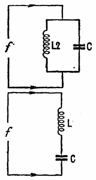
FIG. 1
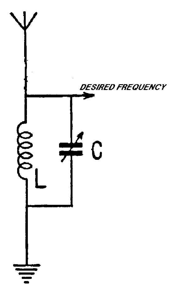
FIG. 2
If we replace the fixed capacitor in the circuit by a variable type the resonant frequency may be varied over a range determined by the maximum and minimum capacity of the capacitor plus the inductance value of the coil. For instance, a variable capacitor of 500 pfd maximum in parallel with a coil of 200 microhenries (200 pH) will cover the medium wave broadcast band of 200 m to 550 m (1500 kHz to 545 kHz), and enable the circuit to resonate at any desired frequency within it.
At this point we need to look at one of those anomalies that can so easily confuse anyone learning about vintage radio. When you tune a radio set it is natural to assume that you are selecting a particular station and rejecting others, so you might well imagine that the tuning knob operates the variable capacitor of an acceptor circuit. Not so; tuning is almost in every case carried out with a rejector circuit, so what you are doing is accepting all the stations you don’t want and rejecting the one you do! This needs to be explained.
Imagine the rejector circuit being connected to an aerial and earth system. At any time of the day hundreds of different frequencies put out by hundreds of broadcasting stations will arrive simultaneously. To all those differing from the resonant frequency of the circuit the latter will act as a short circuit and they will be returned to earth, leaving maximum voltage at the resonant frequency available for use at the point marked on the diagram.
A use for the acceptor circuit
Sometimes it is handy to be able to select just one particular frequency and to suppress it rather than make use of it. This happens when a radio set is sited near a very powerful transmitter which threatens to ‘swamp’ it, that is, to break through onto other stations. A case in point occurred when the BBC opened a high power transmitting station at Droitwich in the mid-1930s; many sets of the day located fairly close to the site were unable completely to tune it out and it appeared as a constant background to other stations. To over come this new receivers were equipped with a ‘Droitwich rejector’ and you will probably come across sets with this feature. The ‘rejector’ in fact usually consisted of an acceptor circuit that could be tuned accurately to the Droitwich frequency and short circuit it out. You will find as we go along that apparently contradictions in terms are not uncommon in vintage radio.
Frame aerials
It is possible to wind the tuning coil of a receiver on a large former which itself can pick up signals from radio stations without the need for an outside aerial or earth. They were, of course, widely used in portable and transportable receivers, very often being wound on a wooden frame just big enough to fit snugly inside the cabinet. Frame aerials have directional properties, maximum signal strength being received when the side of the frame is pointing towards the station. Apart from portability, they are also useful for separating two competing stations on nearby wavelengths.
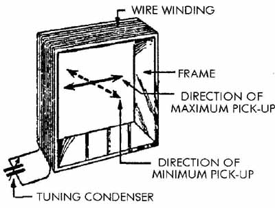
FIG. 3
Air cores and iron dust cores
So far all the tuning coils we have considered have been ‘air-cored’, which does not necessarily mean that they are wound on thin air! Some short wave coils are wound with thick wire which needs no former, but these are called ‘self-supporting’ coils. It is coils wound on some kind of non-metallic former, such as a hollow paxolin tube or a wooden dowel, that are known as air-cored. It is not possible to use a soft-iron core to increase the inductance because it would introduce too many losses, but early in the 1930s it was discovered that powdered iron bound with some glue-like medium can be molded into highly effective cores for coils. Iron-dust cores, as they are called, increase inductance values and enable coils to be smaller in physical size yet to be more efficient than air-cored types. A later development was to make the cores movable within the cores so that the inductance could be altered over a limited range, thus enabling coils to be matched closely, a very important
property in radio receivers. There are two popular methods of making the cores adjustable, the first being to form them with a screw thread which fits into internal threading in the coil former; the second is to have smooth cores into which are molded thin brass rods, threaded to fit into a fixed nut at one end of the former, so that turning the rod moves the core to or fro.
Permeability tuning
An extension of the movable core principle is to reverse the usual tuned circuit by having a coil of variable inductance in association with a capacitor of fixed capacity. This sort of tuning was very popular in receivers featuring push button tuning, employing a selection of coils each with a limited frequency range, e.g. 200—300m, 300—400m and so on. It was also occasionally used in the main tuning in compact sets, particularly automobile receivers where a conventional tuning capacitor would have required too much space.
Ferrite rods
Appearing towards the end of the tubes (valves) era was a remarkable non-metallic magnetic material called ferrite which, like iron dust, can be molded into any convenient shape but which has far greater powers of enhancing inductance. Miniscule coils employing ferrite cores can be made, but the best- known use of the material is the ferrite rod aerial, which took the place of the conventional frame aerial in portable and transportable receivers.
We have now seen how it is possible to tune in desired radio stations. We now need to know the principles on which they work, which in turn will enable us to understand how radio receivers work. First, though, we need to look at the device that made broadcasting possible, the valve.
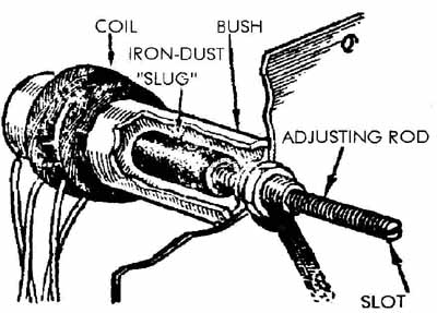
FIG. 4 A typical arrangement for a coil fitted with an iron-dust core having
a threaded brass rod for adjustment purposes.