What you need to know about tubes (valves) (part 2)
High, medium and low impedance tubes (valves) each have certain advantages over the others which make them suitable for specific jobs in a radio receiver. Taking them in order, high impedance types are best suited to what are called resistance- coupled amplifiers, used to build up weak voltages or signals. The circuit of a typical example, with batteries to supply the filament, the anode voltage and the grid bias, is shown in FIG. 1. As mentioned in the previous section, the optimum value for the load resistor in the anode circuit of the triode is usually calculated to be about 2 or 3 times that of the Ta of the tube (valve) and is typically of between about 50 k-Ohm and 1 M-Ohm. Also, as mentioned earlier, the voltage from the battery used to supply the anode is dropped across the load resistor according to the current passing through the valve, which again is dependent on the grid voltage. A varying voltage on the grid, such as might be obtained from a microphone, causes the anode current to move up and down, thus altering the amount of voltage drop across the load resistor.
Once again, the voltage swing here is much greater than that at the grid. It is also in the opposite phase, an important point which gives the tube (valve) its ability to oscillate, of which more later.
Note that in the diagram the incoming signal to the grid is between the latter and the GB battery, whilst the output is between anode and HT battery. For practical purposes the impedance of new batteries may be taken as very low, so the incoming and outgoing signals are effectively both with respect to filament (as batteries age the impedance rises, so they are usually by-passed by a large value capacitor to offset this).
Normally the amplified signals at the anode are coupled by a capacitor to the grid of another tubes (valves) used either to provide further voltage amplification or to drive a loudspeaker (we shall look at this application shortly) with the value of the con denser chosen to have a low reactance at the lowest frequency expected to be handled by the amplifier.
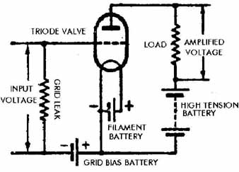
FIG. 1
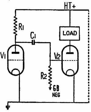
FIG. 2 How one amplifier tubes (valves) may be used to drive another. Typical
values for the components: R1, 100 K; R2, 1 M; C1, 0.01 F.
In all radio receivers there is what is called an ‘earth line’ to which the negative of the HT and LT batteries and the positive of the GB battery are connected. In the vast majority of sets likely to be encountered by the reader the earth line will be the metal chassis on which the set is built, therefore it is customary to refer to these as inputs and outputs, and voltages to be referred to as ‘with respect to chassis’. These terms will be used extensively through this guide. In this respect, in the diagram the resistor in the grid labeled ‘grid leak’ is provided to allow any electrons on the grid (which eventually would build up as a negative voltage) to leak away back to the filament. In each and every tubes (valves) application there must be a return path between grid and filament or chassis.
Another type of amplifier, and one which was used extensively in the 1920s and early 1930s, employs an inter- tubes (valves) or audio-frequency (AF) transformer in the anode circuit instead of a resistor. The DC resistance of the transformer primary, through which the anode voltage passes, is relatively low and little voltage drop takes place. However, its AC impedance may be quite high, in the neighborhood of several thousand ohms and for optimum performance is best ‘matched’ to a medium impedance valve.
In this type of amplifier the change of voltage at the anode is very small although the ‘a fluctuates considerably in accordance with the signal input to
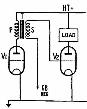
FIG. 3 The circuit of a transformer-coupled amplifier the grid. This effectively
results in a steady DC ‘a plus an AC component, which induces voltage into
the secondary of the transformer. Typically this would give a step-up ratio
of between 1:3 and 1:5 (although as much as 1:7 might occasionally be encountered),
providing a high value of ‘drive’ at the grid of the next valve.
Before we move on to low impedance tubes (valves) it is worth looking at two variations on transformer coupling which were both very popular in tubes (valves) radio sets. One drawback of the steady DC passing through the primary of the transformer was that it tended to magnetize the laminations and inhibit its performance. To get over this problem the parallel- feed (‘parafeed’) transformer circuit was developed. In effect it is a combination of resistance and transformer coupling, with the primary of the latter being fed via a capacitor from the anode of the valve. Thus only the AC component passes through the primary and no magnetizing takes place. Because of this parafeed transformer laminations may be made of very small size from a light steel alloy and the complete job is only a fraction of the size of a conventional type.
A further development of the parafeed technique is to use an auto-transformer with a single tapped winding, which simplifies and cheapens manufacture and enables an even smaller finished product to be made.
Low impedance tubes (valves) are used chiefly in the output stages of receivers to drive the loudspeaker. For this job power is required, calling for a tube (valve) which will pass a fairly heavy anode current, and typical battery output triodes of the 1920s had an impedance of between about 2000 Ohm and 4000 Ohm, and passed a current of between about 10 mA and 20 mA.
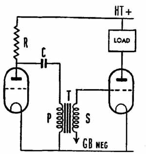
FIG. 4 The circuit of a parallel-fed or ‘parafeed’ transformer coupling in
which no HT current passes through the primary. Typical values for R: 50 K;
for C, 0.25 F.
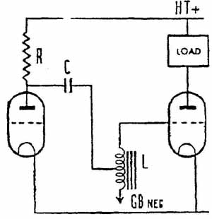
FIG. 5 Parafeed coupling using an auto-transformer
Before going into this application further we need to look at the different types of speaker. The earliest were effectively just a large earphone attached to a horn which amplified the relatively weak sounds it produced.
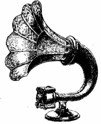
FIG. 6 A typical horn loudspeaker of the early 1920s (Amplion)
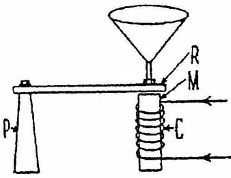
FIG. 7 Diagrammatic layout of a moving-iron loudspeaker. Reed ‘R’ to which
the cone is attached, is mounted on pivot ‘F’ a very small distance from magnet
‘M’ on which is wound coil ‘C’.
The end result was a surprisingly large amount of volume but with an extremely restricted frequency response, despite the claims in advertisements for ‘life-like tone’!
By the late 1920s horn speakers were obsolete and the reader is very unlikely to come across one except as a collector’s item. They were superseded by the moving-iron or ‘cone’ type in which a reed-like armature was held close to a small permanent magnet on which was wound a coil corresponding to one of those in an earphone. Attached to the armature was a paper cone flexibly mounted on a metal frame to permit it to move to and fro. Variations in current through the coil caused the armature and thus the cone to vibrate and thus reproduce the speech or music from the set. Moving-iron speakers were much better than horns and despite the upper and lower frequency response still being limited, can still sound surprisingly good if heard in isolation, and not compared with modern types. They lasted well into the 1930s and the reader has a fair chance of coming across one.
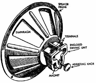
FIG. 8 An actual moving-iron loudspeaker in chassis form. The adjusting knob
alters the spacing between reed and magnet.
The impedance of the coil in a moving-iron speaker was probably in the region of 2000 Ohm, suitable to provide a reasonable match if wired directly into the anode circuit of one of the battery output triodes mentioned above. As with inter- tubes (valves) transformers the passage of DC through the winding caused a magnetic effect, and care had to be taken to wire the speaker in such a way that the magnetism aided and did not oppose that of the permanent magnet, which otherwise would gradually have been demagnetized. For this reason some sets used a similar arrangement to that used for parafeed transformers. A large LF choke with a suitable impedance took the place of the loud speaker winding, with the latter fed via a capacitor of about 2 pF, which permitted the AC component to pass but blocked the DC current. This system was particularly favored in the early mains powered sets (q.v.) which have much more powerful output tubes (valves).
By far the best loudspeaker design to appear in the 1920s was the moving-coil type. Despite being nearly 75 years old, its principle is still being used today in countless millions of radio sets and amplifiers. FIG. 9 shows how it works. At the centre of a light cone, very flexibly mounted, is a small cylindrical coil (the speech coil) wound on a thin former. The speech coil sits within the poles of a circular magnet, and is coupled to the output valve. When the varying voltages produced by speech and music are passed through the coil the electro magnetic effect which is produced either assists or opposes the existing magnetic field and causes the coil to move backwards or forwards, in turn moving the cone and producing a faithful reproduction of the original sound.
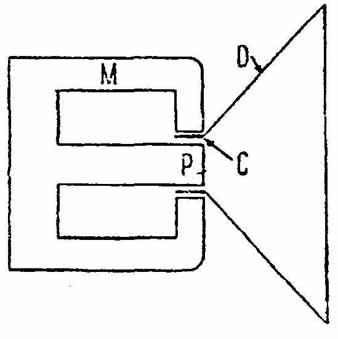
FIG. 9 Diagram of how a moving-coil loudspeaker works. Mounted on the diaphragm
D’ is the speech coil ‘C’ positioned around the centre pole ‘P’ of the magnet
‘M’.
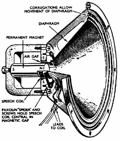
FIG. 10 A typical moving-coil loudspeaker of the mid-1930s. Note the output
transformer mounted on the chassis. A common practice.
The speech coil consists of only a few turns of fairly thick wire and thus has an impedance of only a few ohms (in practice between about 2 ohm and 16 ohm). This is far too low to match even the lowest impedance output tubes (valves) and so a step-down transformer has to be used. This brings us to another tubes (valves) characteristic which is always quoted with respect to output tubes (valves). It is termed the optimum load, abbreviated to Ra with upper-case K to distinguish it from Ta for tubes (valves) impedance. The required ratio of the output transformer, as it is called, is obtained by taking the square root of the Ra divided by the impedance of the speech coil. To take a practical example, to match a tube (valve) with a recommended Ra of 9000 ohm to a speech coil of 3 ohm, divide the last figure into the first to obtain the answer 3000. The square root of this is just under 55, so the transformer ratio would be 55:1.
Note that all early examples of the moving-coil speaker used an electromagnet, called a field magnet, rather than a permanent type as in the 1920s and early 1930s — it was not easily possible to make the latter of sufficient power. Typically the magnet was energized by a 6V storage battery, which made such speakers expensive to buy and own. A short-lived development was the field coil which could be energized from the mains and thus gave rise to the name ‘mains energized loud speaker’. This term is all too often misapplied to later types with fields powered by the HT supply of mains operated receivers, properly known as ‘HT energized speakers’. Always be suspicious of any speaker described as ‘mains energized’ because there is a 99% chance that it won’t be!
The development of new alloys in the later 1930s made possible small and efficient magnets (and in turn smaller speakers for portable sets), but energized types remained popular for certain jobs right into the 1950s and they will often be encountered.
The triode as oscillator
In the circuit of FIG. 11 is shown a simple oscillator circuit working on the feedback principle. L1 and L2 are respectively the primary and secondary of a high frequency transformer: in addition L1 and C1 form a tuned circuit. The action of the circuit is as follows: assuming that the LT battery is already connected, as soon as the HT supply is switched on (t anode current will start to flow in the tube (valve) (t As the current passes through L1 the resulting magnetic effect causes a voltage to be built up across L2, which is wound so that the voltage is positive on the grid with respect to the filament. As we have seen, making the grid of a triode positive increases the anode current and thus increases the positive grid voltage still further. This action continues until the peak current of which the tube (valve) is capable is reached (t2), the time taken to attain this being determined by the resonant frequency of L1 and C1. At this point the anode current begins to fall back (t3), causing an opposite voltage to be built up across L2 and making the grid negative with respect to filament and thus further reducing the anode current. Eventually cut-off point (t4), is reached, and with anode current ceasing, the negative voltage on the grid collapses, permitting the tube (valve) to start drawing anode current again and repeating the sequence of events over and over again as long as the HT supply is connected. The result is a continuous oscillatory voltage built up across L1 and C1 at their resonant frequency. By choosing suitable values of inductance and capacity for L1 and C1 any desired frequency of oscillation may be obtained.
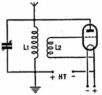
FIG. 11
In the next section we shall look at how the two abilities of the triode to amplify and to oscillate are combined to make possible the broadcasting of speech and music as electromagnetic waves. This in turn will enable us to discuss how the latter may be received and converted back into audible sounds.