A. INTRODUCTION.
Many factors must be considered in the correct selection and application of resistors, and it is imperative that the correct type, wattage rating, resistance value and mounting be chosen to accomplish the desired results. In subsequent paragraphs an endeavor is made to list the more important or critical factors involved and to furnish helpful data for use as a starting point prior to actual tests. Some of the factors and data have been reviewed previously in Section III, TYPES OF RESISTORS, and in these instances, further discussion is purposely omitted to avoid repetition.
As mentioned in the introductory sections, a standard method of testing resistors is established on which catalog ratings are based. In ninety-nine out of one hundred resistor applications, the standard test conditions do not prevail. Four basic factors that should be remembered when applying resistors include:
a. Resistors are generally mounted in housings or enclosures and with other components, thereby restricting free ventilation.
b. Other components may be damaged by heat generated by a resistor.
c. Temperature of components may increase the temperature rise of a resistor beyond a safe value.
d. High momentary surge voltages may cause excessive voltage between resistor coils or windings.
B. GUIDE FOR RESISTOR SELECTION.
When determining the type and rating of a resistor, the following data will serve as a guide:
1. Load versus Temperature Rise Curves - These curves for Vitrohm resistors are given on Page 60.
2. Derating Curves for Various Ambients--The curves in Figure 4-3 show how the power handling capacity of a Vitrohm resistor is reduced as the ambient temperature rises. For example, a resistor is rated at 100 watts for a 300°C rise, at an ambient temperature of 40°C. If the resistor is operated at an ambient temperature of 100°C, it must be derated by 31 percent, and its actual rating at this ambient temperature (340°C hot spot) is 100 x .69 = 69 watts.
3. Derating Curve for Various Altitudes-The curve in Figure 4-4 compares ratings of Vitrohm resistors at various altitudes from sea level up to 80,000 feet, under constant ambient temperature conditions ( 40°C). From sea level up to 2,500 feet full nominal watt rating is retained, but for higher altitudes the rating of the resistor must be reduced.
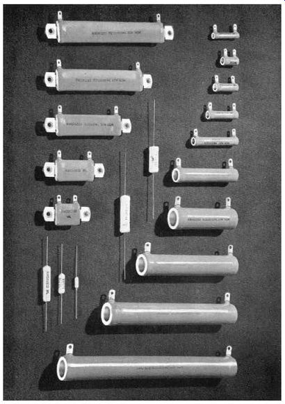
Figure 4-1. Typical Vitrohm power resistors designed and manufactured in accordance
with Military Specification MIL-R-26.
In selecting resistors for airborne equipment operating at high altitudes, the derating percentages given in Figure 4-4 are used to further derate in order to compensate for lower atmospheric pressure.
NEMA and ASA recommend that control apparatus designed for operation at altitudes above 6,000 feet, but not above 15,000 feet, shall be derated as follows:
a. Continuous-duty resistors shall be de-rated to 75 percent of their normal wattage rating.
b. Intermittent- and starting-duty resistors shall be applied on a duty cycle selected on the basis of the next higher "time-on" classification.
4. Derating Curves for Grouping Resistors - For Vitrohm tubular resistors see curves on Page 61.
5. Derating Curves for Enclosures-Refer to curves on Pages 61 and 63.
6. Intermittent-duty Curves-For Vitrohm and Rib flex tubular resistors see Pages 67 and 87 respectively.
For Edgeohm resistors refer to Page 94.
7. Thermal Capacity--In some applications, using non-embedded resistor construction, it is necessary to calculate the temperature rise of res1st1ve conductors that are under load for very short time intervals such as one or two seconds. In such applications the heat absorption characteristics rather than the radiation or convection qualities become increasingly important.
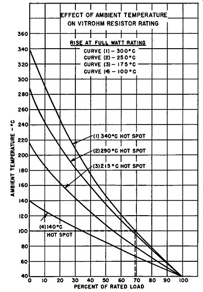
Figure 4-3. Effect of Ambient Temperature on Vitrohm Resistor Rating
Assuming that a ribbon-type resistor such as Edgeohm is subjected to a current of 100 amperes for two seconds, the temperature of the ribbon is calculated as follows: With a resistive conductor having specific heat of 0.1, a total weight of 0.04 pound and a resistance of 0.1 ohm, the wattage dissipated becomes:
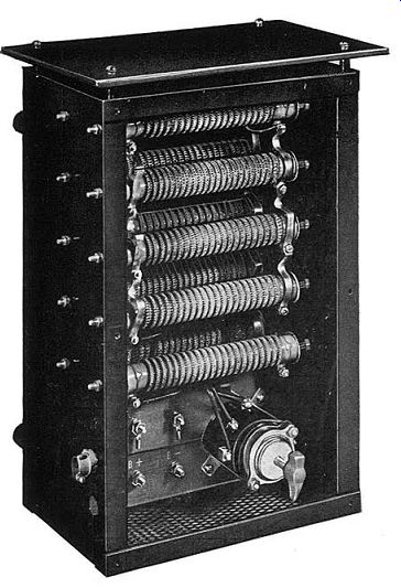
Figure 4-2. Battery Charging Resistor Assembly using Ribflex Resistors mounted
in Dripproof Enclosure. Enclosure cover removed.
W = 1002 x 0.1 = 1000 watts
Since one watt is equivalent to 3.412 BTU per hour, 1000 watts equals 1000 times 3.412 or 3412 BTU per hour. The BTU per 0.04 pound for two seconds is:
2 X 3412
= 47.4 BTU
0.04 X 60 X 60
Since one BTU will raise the temperature of one pound of material having a specific heat of unity one degree Fahrenheit, the temperature rise of the ribbon equals:
47
.4 = 474°F or 263°C
0.1
8. Maximum Voltage Limitations--Data for Vitrohm tubular resistors are given on Page 65.
9. Surge Voltage of Steep Wave Front-In applications where extremely high-voltage surges of steep wave fronts are known to occur for very short time intervals ( milli-seconds), surge-wound resistors should be used.
Surge-wound resistors have wider spacings between turns at each end of the tube. This construction is used for protection against high voltages between turns at the ends of the winding. It also affords additional insulation resistance between turns.
10. Rating versus Number of Taps - Multi-tapped resistors have the same free-air watt ratings as those with only two end terminals. Because of this it is unnecessary to lower the rating of a resistor with one or more taps. However, multi-section resistors do require derating since the external radiating area is less than that found on multi-tapped units.
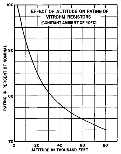
Figure 4-4. Effect of Altitude on the Rating of Vitrohm Resistors
C. ABNORMAL OPERATING CONDITIONS.
In the following paragraphs are discussed several abnormal operating conditions where Vitrohm construction is particularly recommended.
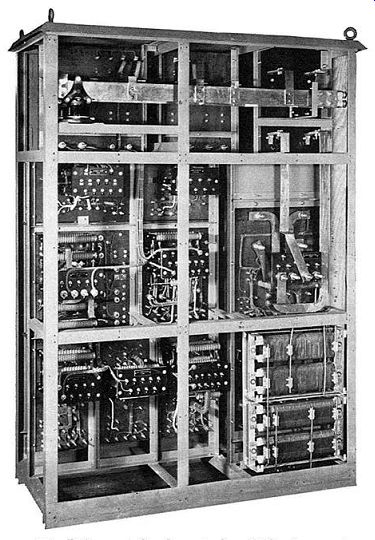
Figure 4-5. D.C. centralized control cubicle for engine room auxiliaries built
by Ward Leonard. Banks of Ribflex resistors are used for motor starting and
accelerating purposes. For motors above 25 H.P. Edgeohm resistors (lower
right) are used.
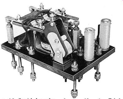
Figure 4-6. Special heavy-duty relay assembly using Tubular Resistors with
flexible wire lead terminals
Photo courtesy of Electric Regulator Corporation
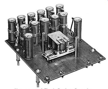
Figure 4-7. Miniature direct-acting voltage regulator utilizing Adjustohm
tubular resistors.
1. High Humidity - Resistors operated in damp places, indoors or out, must be protected by a coating which will not permit moisture to enter and cause deterioration to the resistive conductor. The crazeless enamel used in the Vitrohm resistor precludes any possibility of electrolytic action, by completely sealing the resistive conductor against entrance of moisture.
2. Corrosive Atmosphere--Many acid or alkali fumes can cause rapid deterioration of a resistor surface, there by exposing the conductor to the damaging atmosphere.
The vitreous enamel of the Vitrohm resistor is resistant to many acids and alkalies and can therefore be operated in such atmospheres without any precautionary measures other than covering the terminals with a protective coating.
3. Vibration and Shock--Resistors used in mobile equipment or in locations where severe vibration is encountered must be so constructed that their function will not be impaired. Vitrohm resistors, because they are a homogeneous mass, have great mechanical strength to withstand severe physical shock or continual vibration without damage.
4. Overloads--High momentary overload conditions impose considerable strain upon a resistor due to the strong induced magnetic forces. The high heat conductivity and the intimate contact of the vitreous enamel with the resistive conductor of Vitrohm resistors ac counts for their ability to withstand heavy momentary overloads.
5. Salt Atmosphere--Operation of resistors in the presence of salt atmosphere can prove troublesome unless the resistors are either suitably enclosed, or are capable of withstanding the corrosive action of salt. The protective covering of Vitrohm resistors makes them suitable for operation in such atmospheres without en closures of any kind.
Photo courtesy of Westinghouse Electric Corp.
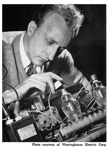
Figure 4-8. An ignitron welding control unit used for welding aluminum aircraft
subassemblies undergoes test. Vitrohm tapped resistor, a vital component, is
illustrated in lower right hand corner.