THE AB BOX
THE ULTIMATE TEST of any audio equipment is the listening evaluation. Often we make comparisons to a known standard. Thus the AB Box: a method of comparing high level sources, phono preamps, power amps, speakers, and even phono cartridges.
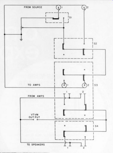
Fig. 1
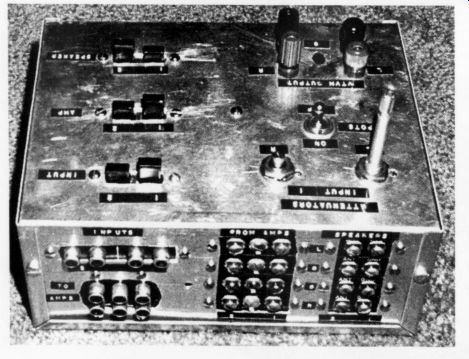
Fig. 2
Finding appropriate switches was my most difficult problem. The Switch-Craft "Multi-Switch" (available from Bur stein-Applebee) is well suited to this application. This set of ganged double throw units rated at 3A at 125V will handle about 100W into 4 ohms.
Fig. 1 is the circuit diagram for one channel of an AB box. The level controls match levels between two components: for example, two speakers of differing efficiencies may be compared by simultaneously operating switches S1 and S4, using the level controls in the circuit with the more efficient speakers.
You may want to consider adding switching for the VITVM output so it can be connected to either the amplifier input or the amplifier output (4PDT required).
Another improvement would incorporate four-way switching facilities.
Fig. 2 is a photo of my AB box to give an idea of layout. The chassis is 6" x 8'' x 3.5'' Bud Box. I have used my box for comparing:
1. Double Advents vs. single Advents.
2. Double Advents vs. Magneplanar (biamped).
3. Different bass speakers with the Magneplanar tweeter-midrange.
4. Power amps.
5. Phono amps.
No problems have occurred. The switching transients (as observed on a scope) are acceptable for 100 watt amps.
RICH F. DAVIDSON; Idaho Falls, ID 83401
RE-POWERING SP-3A-1
I AM DELIGHTED that many people are now building their own versions of SF 3A-1. It is a great preamplifier. However, I believe its maximum performance cannot be obtained unless the B+ voltage fed to V1 and V4 is actively regulated.
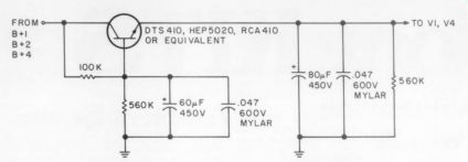
-------- The circuit above will produce good results.
Of course you need not use these exact values. The result is a tightening of the low end and improved high end purity. I have been using this modification since January 1976 with no problems. I know of two other friends who have had similar results.
Audio Research have yet another modification of their own to the SP-3A-1.
This improves transient response while increasing the gain of the high level amplifier (preceding the tone control amplifier). The modification is: 1) remove C47 (5pF), 2) remove R68 (301k, 1 percent), 3) substitute a jumper wire for C39 (1.0 uF, 100V).
This will increase the gain by 3dB along with the aforementioned benefits.
To change the subject, I hope people with Dynaco Stereo 70 amplifiers or others of similar vintage and design will consider that an astonishing improvement in its performance is possible by modification. This can be achieved by combining the basic principles of the ''Brute'' Stereo 70 (appeared originally in Stereophile, 4 / 66. Reprints are available from TAA for $1.50), with some of the design ideas used in the Audio Research D-76 (See TAA 1 7 76). The D-76 has an even larger B+ reservoir than the '“Brute'" 70 and provides voltage regulation of the input stage B+.
Before the D-76 schematic appeared in TAA 1 had rebuilt my Dyna Stereo 70 on a single chassis with two power transformers, two 14 henry Paeco filter chokes (surplus). In other words, a basic power supply very much like that of the original Brute-except my B+ reservoir for the output transformers consists of 350 uF / channel (if I had it to do over I would increase this to more than 500 uF / channel). I went beyond the Brute design by using two active regulators for the 7199 input / drivers, one feeding both pentode halves--the other both triode driver halves. These regulators are, in principle, exactly like the SP-3A-1 regulator: a Zener diode referenced capacitance multiplier, and series voltage regulator (all in one, of course).
Improving the power supply in this way effects a great sonic improvement. I also recommend strongly the replacement of all resistors in the cathode and plate circuits with metal film types. This applies to all amplifiers, such as the SP-3A-1.
These resistors have a definite effect on the sound quality, even carbon film resistors are not as good.
The R-C rolloff network between the pentode plate-triode grid and ground should be minimized (larger resistor, and / or smaller capacitor which will still permit good square wave performance).
This will reduce the load on the pentode plate circuit and improve sound quality.
Partial cathode coupling of the output tube cathodes to the output transformer secondary with the 4 ohm tap grounded as in the ARC D-76 will permit a further improvement which can be quite astonishing. Output tube balance is set with a DC ammeter as shown by the phone jack test points shown in the D-76 schematic.
The partial cathode coupling is a form of negative feedback from the transformer secondary to the output tube cathodes and apparently improves (obviously to the listener) the linearity of the output tube / transformer combination.
Incidentally, the Audio Dimensions manual (issue 3 / 76 p.43) is very good and has some excellent ideas. One or two of my ideas on the Stereo 70 are derived from it-mainly the modification of the rolloff circuit between the two halves of the 7199.
ROBERT K. LeBECK, JR. Mountain View, CA 94040
GETTING THE MOST OUT OF A KENWOOD KX-1030
THE KENWOOD KX-1030 CASSETTE DECK is an excellent three head deck when used properly. Although Kenwood included a built-in dual frequency oscillator with front panel bias adjustments, they neglected to include front panel adjustments for record calibration level, did not design the metering arrangement for easiest use, and do not give proper instructions for setting the bias.
I will discuss how to use the deck properly to achieve the best results. With some lack of convenience you can obtain these results without making any modifications to your deck; however, I will also discuss the necessary modifications for those who prefer to make them.
Kenwood's instructions do not mention that you must turn the Dolby off before adjusting the bias for equal outputs at 400Hz and 10kHz. If you don't and the record calibration levels are not correct, the Dolby circuitry will change the output at the 10kHz frequency and give a false reading, leading to an incorrect bias adjustment.
It is extremely important that in addition to adjusting the bias you also adjust the record level for each channel. If you have a Phillips screwdriver (to take off the deck's top cover), and a small jeweler's size screwdriver, and keep you deck where you have access to the top as well as the front, you can make this adjustment each time you adjust the bias.
Remove the six screws holding the top cover and slide it off. Near the circuit board back you will find two pots marked “VR11" and ''VR12''; these control the record calibration level for each channel. If you have not modified your metering circuit as described below, be sure that the output volume controls are at maximum before you proceed further.
Once you have adjusted the bias for each channel, adjust VR11 and VR12 for a reading of 0dB on the meters with the output volume at maximum. When switching from source to tape you will note they should be the same. Make sure you adjust the pots when the 400Hz signal is generated (recording light is off) to get a more precise adjustment. If you leave the screws off the case you can lift it off whenever you readjust the bias and be able also to readjust the record calibration level. When the record levels are correctly adjusted the Dolby circuitry will be able properly to decode the signals on the tape.
Otherwise the sound will suffer, since the Dolby circuitry will seriously degrade the frequency response.
You can easily forget in the rush of things to turn the output level controls to maximum before adjusting the record calibration level; then you wonder why the recording doesn't sound so good. To prevent this you can modify the deck so the meters always read the full output of the tape, rather than being affected on playback by the output level controls. To make this modification, cut two paths on the circuit board to switch S20 (monitor switch) and solder the terminals together as shown in Fig. 1. You must take off the bottom cover plate to gain access to this part of the circuit board.
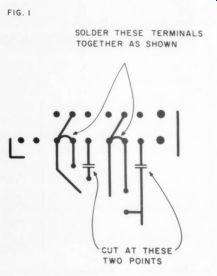
FIG. 1 SOLDER THESE TERMINALS TOGETHER AS SHOWN
All adjustments can be made externally if you remove VR11 and VR12 and rewire them to a dual 20K pot mounted on an outside panel. If you can do a nice job of cutting the front panel (I can't un fortunately), this can make your 1030 a truly easy-to-use outstanding deck. About the only location on the front panel where there is any room available is the upper right hand corner, around where the word “Dolby'' is printed.
An alternative location for the pots is on the back panel. This is far less convenient for making adjustments, but they would be much easier to install and would involve a shorter run for the wires from the circuit board.
Correct steps in calibrating the Kenwood KX-1030 using its internal oscillator are:
1. Adjust output levels to maximum. (omit if you made this metering modification.)
2. Turn Dolby off.
3. Turn on the ''osc."
4. Adjust bias for each channel for equal output of the two frequencies generated by the internal oscillator.
5. Adjust record calibration pots for 0dB. To check this adjustment, switch between source and tape. Levels at 400Hz should be the same.
6. Turn the oscillator off and turn the Dolby back on.
One other valuable feature of the 1030 not even mentioned in the instruction manual is it can be operated with an external timer start. Set the machine up with a timer with the record and play switches depressed. Also depress the pause switch so that the capstan is not against the pressure roller. (Be sure to leave the power on.) When the external timer turns on the power to the deck, the pause switch will automatically be released after some 10 seconds delay and the deck will start recording. Or you could set it up to play so it would wake you up in the morning.
Enjoy!
ROBERT SELLMAN, Haddon Heights, NJ 08035
MORE KT88 SUBS
THE RECENT WEALTH of comments from TAA readers regarding substitutions for the KT88 tube prompts me to share my experiences and observations. First of all, as John W. McConnell (TAA 4 7 78, p-52) notes, the 6550 tube will not work in circuits with adjustable bias where the control-grid resistance exceeds 50k (or 250k for cathode-bias circuits). This is due to grid emission of the output tubes, which causes a disastrous change in grid bias. This bias drift, which will occur under suitable conditions with any tube, appears to be a notorious fault of the 6550-even circuits designed specifically for this tube may require frequent read adjustments. Dropping the value of the grid return resistor helps, but this usually places an excessive load on the driver stage.
You may be able to circumvent this problem by using a combination of grid and cathode bias, but the best solution is probably to choose a more suitable tube.
Mr. McConnell's statement that screen grid voltage is limited to 400 in the 6550 is not quite correct; most tubes permit screen-grid operation at up to plate potential provided the screen is connected to either the plate or a suitable tap on the primary of the output transformer.
Some late-production 6550's have another problem which can cause mysterious fuse failures or even tube destruction. Most old-timers will recall that on the old metal output tubes, pin number 1 was always grounded. In later all-glass tubes, this pin was either missing or dead-ended inside the tube, so constructors often used the corresponding socket terminal as a tie point. However, with recent production runs from at least one manufacturer, grounding this point will result in severe internal arcing.
(There is no similar danger with pin number 6, which is also often used as a tie point).
The 6550 has other disadvantages besides its relatively high cost. Not the least of them is its distortion before feedback which, at about 3 per cent, is a little high. The 8477, recommended by J.A. Thompson (TAA 1/78, p. 46), is both cheaper and lower in distortion under similar conditions. It also has twice the transconductance of the 6550, so its open loop gain will be higher and its closed-loop distortion even lower, but this still is not the best choice. Mr. McConnell's suggestion, the 6L6GC, is much better.
The tube-manual data do not permit direct comparison as the 6L6 requires a somewhat higher plate load, but the distortion is very low and the mismatch is in the direction that reduces both power output and distortion.
I have tried all tubes in my Dyna Mk. III over the past few years in an effort to obtain the lowest distortion before feedback. The best tube I have found so far is the 7027A (By GE). I have been running this tube for about a year, most of the time triode-connected (390 resistor between pins 3 and 4; wire to pin 4 disconnected). As a triode, the tube puts out about half of normal power and almost no higher-order harmonic distortion. One can dramatically reduce veiling by also adding cathode feedback, as in the Stereo +70 mini-mod (TAA 4 / 76, p. 13), but this mod may cause motorboating under certain extreme operating conditions.
I will be glad to send a copy of my modifications to anyone sending me a stamped, self-addressed envelope. I believe any further increase in performance would involve redesign, not just simple modification.
BOB MCINTYRE; 1532 Daytona Drive, Toledo, OH 43612
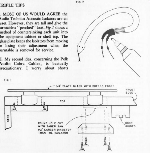
TRIPLE TIPS
1. MOST OF US WOULD AGREE the Audio Technica Acoustic Isolators are an asset. However, they are tall and give the turntable a ' 'perched'' look. Fig. 1 shows a method of countersinking each unit into he equipment cabinet or shelf top. The lass plate keeps the Isolators from moving r losing their adjustment when the turntable is removed for service.
2. My second idea, concerning the Polk Audio Cobra Cables, is basically precautionary. I worry about shorts evolving where the small enamel wires leave the braid and converge to the end connector. You can reduce the risk of a short by completely coating that area with silicon bathtub sealer (see Fig.2). A good application of this seems to cut down the scuffing and flexing of the intertwined conductors.
3. Finally, the Hafler 101 preamp will prove to be an audio amateur's delight (like the PAS-3X, the PAT-4 etc.) However, it has an audible 120Hz buzz when used with lower output cartridges such as the Satin. This buzz, caused by an internal ground loop, can be cured by a few inches of extra wire and a ground lug (Fig.3.).
Other Hafler tips:
a. Having the tone controls switched “out” noticeably rounds off a 10kHz square wave which indicates a supersonic rolloff and possible reduction in slewing capabilities of the high level section. (I haven't decided if I can hear a difference).
b. By all means, use an oscilloscope and a square wave generator to ''zero'' the tone controls.
c. If the pilot light does not go out completely when the unit is turned off, the disc capacitor across the switch is leaking.
If this bothers you, replace the disc with a high quality unit.
JOHN T. PHILPOT
South Holland, IL 60473
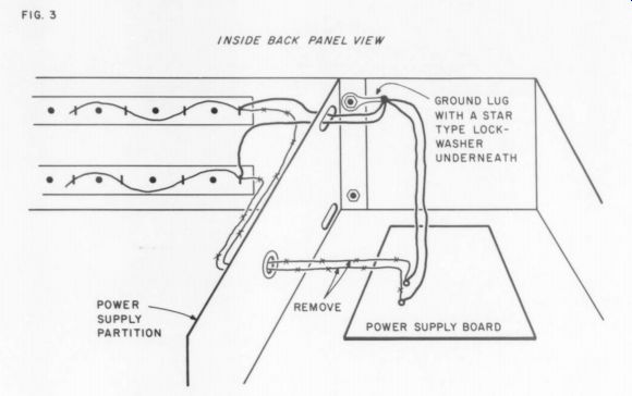
-------- FIG. 3. INSIDE BACK PANEL VIEW
Also see:
Audio Aids, 1/1979, by readers Squires, Hill, Caldwell, Thompson, Winn, Hardwick, Moritko, and White
Build A Microphone Preamp (Audio magazine, Feb. 1979)
Test Reports: Heath's ID 5252 Audio Load, Heath's IG 1275 Sweep Generator