GET A LOAD OF THIS
by Fred M. Gloeckler
THE HEATH MODEL ID-5252 Audio Load is a simple device: four resistors in a box. It's designed to be used as a load for testing audio power amplifiers. It also makes a dandy space heater.
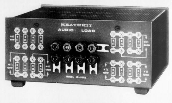
Each resistor is rated at 8 ohms +1 percent at 60 watts dissipation, and is connected to its own pair of five way binding posts. Using the interconnecting links provided, the following load combinations can be obtained:
-------------
---
Power Dissip watts
8 60 16 120 4 120 32 240 2 8
Resistance ohms
Quantity
240 240
---------
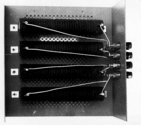
The resistors are mounted in a well ventilated case. Diagrams of the most commonly used load connections flank the binding pats. Flexible l cables connect the ID-5252 to the amplifier under test.
Assembly should take t than an hour. Heavy buss wire connects the resistors to the binding pets. A fairly hefty (50 watt) soldering iron will help ensure solid joints.
Heath supply enough material to make four three-foot long, 12-gauge, two conductor cables with large spade lugs on one end and small lugs on the other. I chose to fabricate two six-foot long cables with large lugs on both ends. The small lugs won't fit the binding posts often used on high powered amplifiers. Heath should provide additional large lugs so the constructor can have a choice.
The four resistors measured 8 ohms +0.56, -0.15, +0.46, and +0.56 per cent respectively when cold. Naturally, when measuring such low resistances, the effects of the meter leads must be subtracted from the readings.
Feeling sadistic, I paralleled all four resistors and connected them to a DC power supply adjusted to 21.9 volts directly across the load (240 watts dissipation). after cooking for a while (though the smell was not exactly delicious), I re-measured one of the resistors. It increased in value very slightly--approximately 0.2 percent.
While I didn't measure case temperature, I do believe Heath's warning that it can approach 231 degrees at full load. Be sure the load box has unobstructed air circulation and can't be accidentally touched when you're testing at high powers.
The round trip resistance of the six-foot long cables was 0.024 ohms, which creates a 0.3 percent error when in series with an 8 ohm resistor. Incidentally, the meter I used for resistance measurements has a specified maximum error of 0.23 per cent at 8 ohms.
When I used a scope to display phase shift patterns, each resistor's reactive component was mainly inductive and, at 100kHz, measured about five per cent of the nominal resistance rating. This works out to an inductance of approximately 0.65uH. The cable inductance was on the order of 1uH.
The interconnecting links permit rapid change of load configuration and minimize the number of test leads to get tangled.
The 12-gauge cable appears ideal for speaker wire (it looks like overgrown zipcord). It would be nice if Heath offered it separately as I haven't seen it anywhere else. (DB Systems, Box 187, Jaffrey Center, NH 03454 now offers such cables.-Ed.) The ID-5252 meets all its specifications and fills a definite need on the test bench.
A novice can assemble it. The $44.95 price seems a bit steep. Do-it-yourselfers may want to investigate the editor's dummy load in TAA issue 2/72.
I highly recommend the ID-5252. Note that you need two for simultaneous testing of both channels of a super power stereo amplifier.
PS. This postscript is aimed at manufacturers of binding posts and ad Test Reports dresses a bothersome problem with equipment from many sources, including some I've built. Why don't binding posts tightened finger tight, grip spade lugs securely? It seems whenever an even light torque is applied via the wire, the lug springs loose. Perhaps a washer would help. The posts on the ID-5252 do have hexagonal flats which can be tightened with a wrench .not too hard, please.
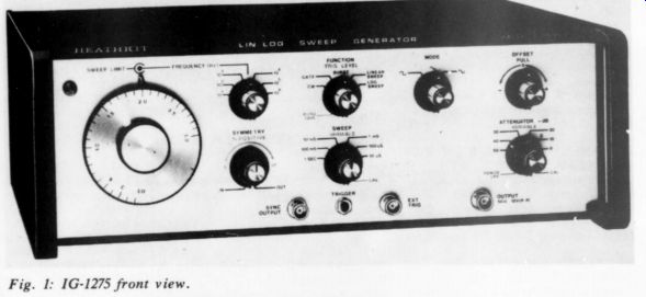
Fig. 1: 1G-1275 front view.
HEATH COMPANY Model IG-1275 LIN /LOG SWEEP GENERATOR
by WALT JUNG
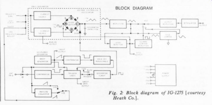
Fig. 2: Block diagram of IG-1275 [courtesy Heath Co.].
HEATH'S MODEL IG-1275 LIN / LOG Sweep Generator introduced in 1977 is a high performance solid state function generator producing the basic waveforms of sine, square, and triangle waves over a wide range of frequencies and amplitudes.
The user can sweep the output frequency over a 1000 / 1 range in either a linear or a logarithmic fashion. In addition to the generated signal's output, sweep (and gate) voltage outputs are available to drive chart recorder inputs for automated X-Y plotting of frequency response. Fig. 1 shows the IG-1275's front panel. The instrument sells for $319.95 in kit form or for $430.00 assembled, from Heath Company, Benton Harbor, MI 49022.
From these basic functional characteristics you will note the IG-1275 might have been designed with the audio test bench in mind. ''Is it useful to an audio amateur?'' and ' 'To what degree?'' are a pair of logical questions. I hope this report will answer these questions, and some general ones on function generators as well, to your satisfaction.
As regards specifications, Heath rate the IG-1275 to perform in accordance with the ratings listed in Table 1. Most of these specifications need little interpretation for the readers, so I shan't discuss these in detail. However, the following ones are of significance to the audio amateur.
The IG-1275's output source is rated at 50 ohms and can deliver 10V pp into such a load or 20V pp into an open circuit. This low output impedance makes it relatively immune to loading effects such as would be encountered in an audio circuit. The 50 ohms output impedance is maintained constant by the 10dB per step attenuator, which follows the output amplifier as illustrated in the block diagram of Fig. 2.
The output selector switch selects one of the basic waveforms (all of which are simultaneously internally generated). The main generator (within the box in Fig. 2), operating in conjunction with the level detector, generates the basic triangle wave. The level detector drives the square shaper / amplifier which generates the square wave. The buffered triangle wave drives the sine shaper circuit which generates the sine wave.
Heath list the IG-1275's basic frequency range as 3Hz-3MHz, but the actual range is greater than this, as these numbers correspond to the full scale limit of a given selected range. The lowest range of x 10, combined with the dial vernier range of 0.03-3, allows a lower limit of 0.3Hz. As you will note from Table 1, the ...
----------
TABLE 1:IG-1275
Performance Specifications.
This unit operates to specifications at 25°C. +5 C ambient after 1/ 2 hour warmup.
Output: 50-ohm source-short circuit protected. 20 volts p-p open circuit. 10 volts p-p into S50 ohm load.
Output Flatness: +0.1 dB to 300 kHz. +0.2dB to 3 MHz.
Output Waveforms: Sine-Triangle-Square. Symmetry continuously variable 5% through 95% to 300 kHz.
Frequency: 3 Hz through 3MHz in 6 range steps on primary decade. 0.03Hz on third decade of X10 range.
Sine Distortion: 1% Less than on the through 10^1 frequency ranges. Less than 0.75% on the 105 frequency range. Harmonics 30dB down on the 10^4 frequency range.
Triangle Linearity: No deviation greater than 1% to 300 kHz.* Square-Wave Rise and Fall: Less than 60nS.
Dial Accuracy: +3% of full scale (10% through 10^6. +4% of full scale at 10°.
Attenuator: 0 to - 50dB in 10dB steps. Variable control 0 to -20dB.
"DC Offset: Signal plus offset, limited to +-10 volts open circuit or +- 5 volts into 50 ohm load.
Time symmetry: Within 1% of full period through 300 kHz.
10! frequency range. Less than 0.5% on the 102
Sweep Generator: 6 ranges. 10 -us through 1-s. Each range may be extended by 100 with the variable control.
Sweep Output: Supplies 0 to 4.5 volt linear ramp at sweep generator rate from a 1000 ohm source.
Sweep Gate Output Connector: Supplies high TTL level for duration of sweep or burst.
Analog Output Connector: Supplies 0 to 6 volts DC for 3 decade span. Less than 100 ohm source.
Sync Output Connector: Supplies 1.5 volt (minimum) peak-to-peak signal from a 50 ohm source.
Voltage Control Input Connector [VCO]: 0 to +5 volts signal for a 3-decade span. 8k ohm input impedance.
External Trigger Input Connector: +(250 mV to 4 volts) with 10k ohms. Triggers on positive slope.
Operating Temperature: 0° to 40°C ambient. Power Requirements: 100 to 135 volts, S0-60Hz, 20 watts maximum. Switch selectable for normal or low line. (200 to 270 volts, 50-60 Hz. switch selectable).
Dimensions: 15" wide, 11-7/ 8" deep. 5-3/ 8" high. (38.1 cm wide, 30.2 cm deep, 13.7 cm high).
* Applicable only on top decade of each frequency range.
* Operates to specifications at 25°C +5°C ambient. All specifications after 1/ 2 hour warmup.
--------------------
...instrument maintains output waveform flatness to within 0.1dB up to 300kHz, a very useful feature for frequency response tests.
As the block diagram implies, you can tune the IG-1275 to a given frequency by three means: the frequency dial, an external VCO input (rear panel), or the sweep input from the secondary generator (shown in the lower part of Fig. 2). The manual tuning arrangement on the front panel consists of a large circular dial calibrated from 0.03 to 3. For manual (non-swept) use, this dial adjusts the output frequency, which is the dial setting times the range multiplier -0.3 x 10 equals 3kHz, for example. For swept operation, an outer lever control knob, when positioned to the desired point on the circular dial, adjusts the circuit to a variable upper frequency limit. The generator then sweeps between the lower limit as set by the circular dial and that set by the outer lever.
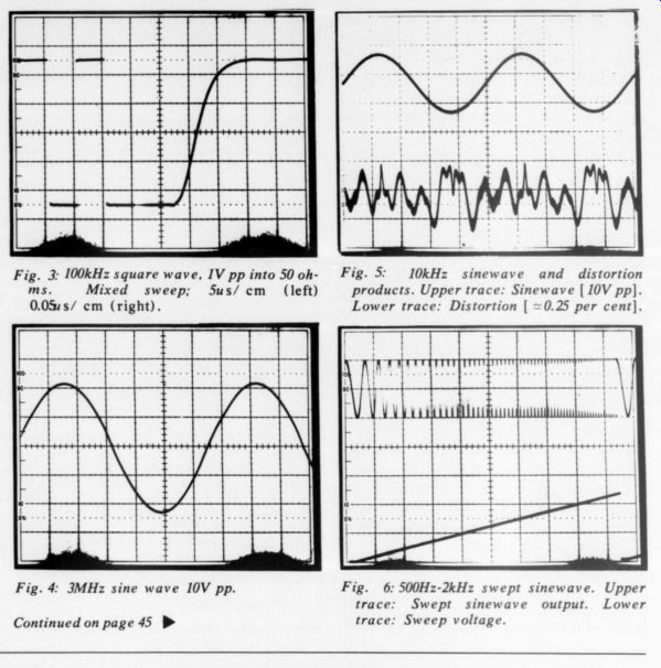
Fig. 3: 100kHz square wave, IV pp into 50 ohms. Mixed sweep; 5 us/ cm (left) 0.05us/ cm (right). Fig. 4: 3MHz sine wave 10V pp. Fig. 5: 10kHz sinewave and distortion products. Upper trace: Sinewave [ 10V pp]. Lower trace: Distortion [~0.25 percent]. Fig. 6: 500Hz-2kHz swept sinewave. Upper trace: Swept sinewave output. Lower trace: Sweep voltage.
The secondary generator part of the block diagram consists of the operational blocks also shown in Fig. 2. In addition to the sweep mode described, which can be selected as either a linear or a logarithmic tuning voltage / frequency relationship, one can operate the generator in a triggered or burst mode, with timing parameters controllable over the ranges shown in Table 1. Also, as I noted, auxiliary voltages are available from these circuits for external uses.
Six different supply voltages power the IG-1275: 15, #15, sad 423V. IC regulators stabilize all but the +23V levels. Operation is from AC sources of either 100-135V or 200-220V, 50-60Hz nominal sources, with transformer taps to optimize for high or low line conditions.
CONSTRUCTION
Discussions such as the above, while necessary to a review of this kind, can never really get the reader into the 'feel"' of how well an instrument is made and how it performs. However, one can obtain a good indication of the complexity and sophistication of this generator from an appreciation of its internal parts and the time necessary to build it. It took me no less than 14 hours to build this kit.
Beyond this you should allot another two hours for setup and calibration adjustments. You might make the setup in less time; 1 had a couple of diodes back ward, and correcting such minor mistakes
does consume time. Depending upon your overall level of experience, the above times might be higher but I doubt they would be much lower.
This kit is complex and not one I would recommend to the inexperienced. Just the test and calib. Of the manual, for example, occupy 10 pages.
Further, you will need a scope plus AC and DC meters as a minimum, and prefer ably also a counter, an HF AC meter, and a THD analyzer to accomplish these tests.
On the other hand, I hope these words of caution do not unduly scare anyone off.
The kit manual is one of the finest I have ever seen, with detailed pictorials in booklet form, and even troubleshooting logic trees to isolate faults.
A look inside the generator gives one a glimpse of construction techniques and component quality. The circuitry is divided into three boards. The ICs use sockets to ease troubleshooting, parts are of good quality, particularly at critical points: for example, this kit uses more precision (1 per cent) film resistors than any other I have seen-you can spot many of them on these boards.
The kit uses a large number of trimmer pots to set up calibration, and most of them are the open frame carbon type. I suppose their attractive low cost is the chief reason for including trimmers of this type; but trimmers and controls are a major source of problems, and this type of control is one of the least reliable. I would like to see some multi-turn cermet trimmers used in a device of this performance class. I am surprised Heath would include ceramic deck, silver contact switches, and BNC connectors in this instrument, but not a comparable quality trimmer.
PERFORMANCE
Before discussing the IG-1275's performance, some comment is in order on what one ought to expect from a function generator.
First of all, perhaps not everyone is aware of the fundamental difference between the more familiar sine wave generator and a function generator. A sine wave oscillator of the Wien bridge (or other) RC circuit variety generates high purity sine waves such as a basic output; other waveforms such as square or triangle waves, if desired, must be generated separately. A function generator naturally generates a triangle and square waveform, and the triangle can be shaped into a sine wave. Beyond this, another key difference is that the function generator can easily be voltage tuned or swept; this is a major task for an RC sine wave oscillator. On the other hand, however, function generators produce sine waves by a shaping technique which is quite distortion-prone, while RC sine wave oscillators easily produce distortion levels well below 0.1 percent.
So one might more aptly describe the difference between the two types of instruments in terms of their uses. You use sine wave oscillators for distortion and frequency response tests and gain checks, while function generators are useful for a variety of tasks. You can easily make transient response tests-such as rise time, fall time, and slew rate-with the function generator's square wave output, while the triangle output serves to rapidly check for crossover distortion, general linearity, and clipping levels. The sine wave output is most useful for gain and frequency response checks; its distortion is generally too high for testing the current class of amplifiers, being typically in the 0.5-1 per cent THD class and rising at higher frequencies. Those are the major performance differences; we now discuss some selected IG-1275 performance patterns.
Fig. 3 illustrates the relative quality of the IG-1275's output square wave. This photo shows 100kHz square wave into a 50 ohm load at a 1V pp level. The left portion of the photo is a time base of Sus / cm, while the portion to the right is at 50 nanoseconds / cm (100 times faster). Note that the rise time is on the order of 60ns as is the fall time (not shown).
Quite often in function generators the waveshape quality deteriorates rapidly at higher frequencies. Although this is true to some extent in the IG-1275, the 3MHz 10V pp sine wave shown in Fig. 4 is still of reasonable quality. At lower frequencies (as the sine wave distortion specification implies) distortion is much lower.
Fig. 5 shows a dual trace display of the IG-1275 output (top) and the distortion products with the fundamental filtered out (bottom). The conditions are a 10kHz, 10V pp sine wave, and the distortion measures about 0.25 per cent. Low sine wave distortion in a function generator, particularly over a wide frequency range, is a particularly tough circuit nut to crack.
The IG-1275 uses a six segment waveform shaper, with four separate trims to minimize distortion.
Fig. 6 is a dual trace photo of a linearly swept waveform (top) and the sweep voltage (bottom), showing the direct control of generator frequency by a voltage. Although I show a sine wave output here as one example, the output could just as readily be a square wave or triangle, if desired. I purposely kept the swept frequency span narrow here so that individual cycles could be seen and also seen to be increasing. Were a greater span used, or the sweep logarithmic, the relative frequency change would not be as apparent.
SUMMARY
I find the IG-1275 to be a highly useful audio bench tool, almost as useful as a THD analyzer and scope. The design is relatively sophisticated, as is the completed kit's performance. For this reason not all audio amateurs will find this kit immediately useful.
For those who take their audio lab work seriously, I would rate the IG-1275 well worth considering as a standard tool. The construction and parts selection quality (except as noted) are good, and the instrument should give good service for years to come. If you add a plotter, an instrument of this type can make frequency response measures a snap.
Also worthy of mention is a companion kit, the IG-1273, a function generator similar to the IG-1275 but without sweep capability. It is available in kit form for $189.95, or assembled for $240.00.
++++++++++++++
Also see:
Audio Aids, 1/1979, by readers Squires, Hill, Caldwell, Thompson, Winn, Hardwick, Moritko, and White
Build A Microphone Preamp (Audio magazine, Feb. 1979)
LETTERS (with CORRECTIONS)