The Advent MPR-1 Microphone Preamp--A two-channel, transformer input, control-less amp for Advent's 201A.
BY FRED M. GLOECKLER, Contributing Editor
WHEN ADVENT designed the model 201 cassette recorder, they left out the usual mediocre microphone preamplifier and offered the MPR-1 as a high quality outboard preamp to live recording enthusiasts. Perhaps unique to the consumer market, the MPR-1 incorporated input transformers so it could be used with professional quality, low impedance microphones.
Since the MPR-1 no longer is in production, Advent graciously has permitted us to offer it as a construction project. It easily can be adapted for use with equipment other than Advent's.
CIRCUIT DESCRIPTION
Fig. 1 is the MPR-1 schematic diagram. Only one of the duplicate channels will be discussed.
The input transformer, T101, has a 1 to 10 turns ratio which provides a 20dB voltage gain. The transformer minimizes noise generated in the input stage and permits use of balanced microphones and cables. The input impedance, set by R101 as reflected back to the transformer primary winding, is nominally 1,000 oh ms. This is typical of high quality mike preamps which, generally, do not match the low (150 to 200 ohms) microphone output impedance. Several professional condenser microphone manufacturers specify their mikes should not be loaded with less than 1k ohm.
The input transistors, Q101 and 103, are connected as a ''long-tail'' differential pair. The DC operating level is set to half the supply voltage by R121 and 122.
Q101 is biased through the transformer secondary. Q105 is a current driver for Q107, the output transistor.
Feedback resistors, R117 and 107, set the amplifier gain to 40dB for a total gain, including the transformer, of 60dB.
----------------
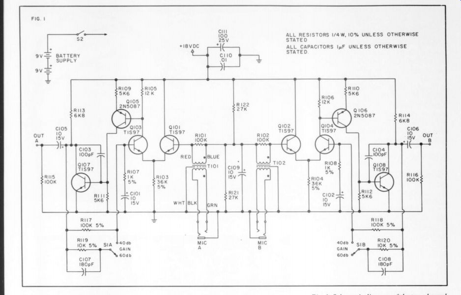
Fig. 1: Schematic diagram of the two channel amplifier. Note the bilateral channel arrangement.
------------
Parts List:
R101,102 100k R103,104 36k 5% R105,106 12k R107,108 1k 5% R109,110 Ské6 R11, 112 S5k6 R113,114 6k8 R115,116 100k R117,118 100k 5% R119,120 10k 5% R121,122 27k All resistors 1/ 4W otherwise.
10% unless designated C101,102 C103,104 C10s,106 C107,108 C109 C110 C111 1: F@15V radial lead 100pF 1 F 15V radial lead 180pF 1 F 15V radial lead
0.01 ceramic 25V 10 F @ 25V radial lead T101,102
Mike input transformers, Advent, special. Turns ratio 1:10.
Q101,102,103,104,107,108, TIS97 or (preferred) Hitachi 2SC 1345E Q105,106 2NS087
Gold plated phono jacks with insulating bushings used on the prototype are available from:
Component Systems, S556 Personality Ct., Indianapolis, IN 46227
------------------
Switching in R119 and C107 reduces the gain by 20dB. C101 rolls off the amplifier low frequency gain to unity at dc.
Power must be provided by an external dc supply. While the nominal supply voltage is +18Vdc, as furnished by Advent's model 201 recorder or 300 receiver, the circuit will accept a range of +12 to +20 VDC. A pair of 9 volt batteries in series will work well since the current drain is about 3 milliamperes.
CONSTRUCTION
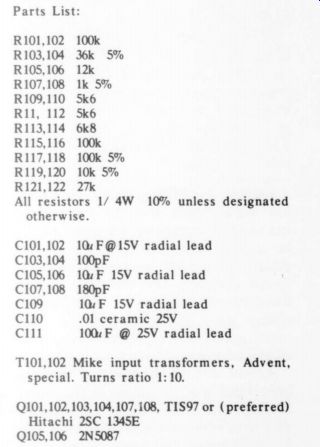
The circuit board component layout is shown in Fig. 2. The short resistor symbols indicate vertically mounted resistors.
Start assembly by inserting and soldering all resistors which lay flat on the board (long resistor symbols). Mount the transistors, vertical resistors, and disc capacitors. Be sure to orient the transistors as shown in the diagram. Observing polarity, install the electrolytic capacitors. If the board mounted gain switch is used (see below), install it.
Advent originally used selected (for low noise) TIS97 transistors in the input circuit. They switched to a Hitachi 2SC 1345E which didn't require selection.
Both have the same lead configuration.
With the green, white and black wires facing the front of the board, press the transformer mounting tabs into the appropriate circuit board holes until the transformer is seated. Clinch the tabs against the foil and solder. Insert the red, white and blue wires into the indicated holes and solder.
Because the MPR-1 works with very low signal levels and the input transformers are unshielded, the board should be installed with care. Use a steel en ck to provide magnetic shielding. Avoid mounting the unit near power transformers or motors. The supply voltage must he well filtered. A self- contained, battery supply minimizes risk of ground loops.
Advent secured, the b at the two transformers or motors. The supply voltage must be well filtered. A self contained, battery supply minimizes risk of ground loops.
Advent secured the board at the two front holes and by means of the board mounted gain switch. 25 / 32"' standoffs were used between board and chassis and 3/32" standoffs between switch and chassis. Naturally, a hole has to be cut in the case for the switch actuator. If you want to remote the gain switch or fix the gain using jumper wires, drill another mounting hole in the board as shown on the component layout.
Advent used 1/4" phone jacks for the inputs. Female XLR-type connectors, made by Cannon, Switchcraft, Amphenol and others, are a better choice. They are almost universally used in the U.S. for professional microphone interconnection.
The contacts are less prone to deposits and other problems which may prevent good connections in low level circuits. A positive latch prevents accidental pull outs. Wiring for XLR-type connectors is shown in Fig. 3. While the pin assignments may seem arbitrary, they are not.
Pin 1 is grounded because it engages before the others. Pins 2 and 3 are connected to preserve polarity if your microphones are wired to international standards.
Positive acoustic pressure produces a positive voltage on pin 2 with respect to pin 3. The input connectors should be grounded at the spot where the supply ground connects to the board. Ground the case only in one place, near the input connectors.
Terminal pins originally attached output and power leads to the circuit board. If you use them, make sure they are firmly soldered to the foil. The commercial MPR-1 had short shielded cables, terminated in RCA plugs, for outputs and power.
My prototype has a homemade steel case, XLR-type input connectors, gold plated RCA output jacks, and a pair of 9 volt transistor radio type batteries for power. the case is styled after Advent's and was cut from steel salvaged from an old chassis. Fig. 4 is the layout diagram for the bottom half. Due to some fuzzy thinking, the prototype isn't quite high enough for the input jacks. The dimensions on the diagram have been corrected.
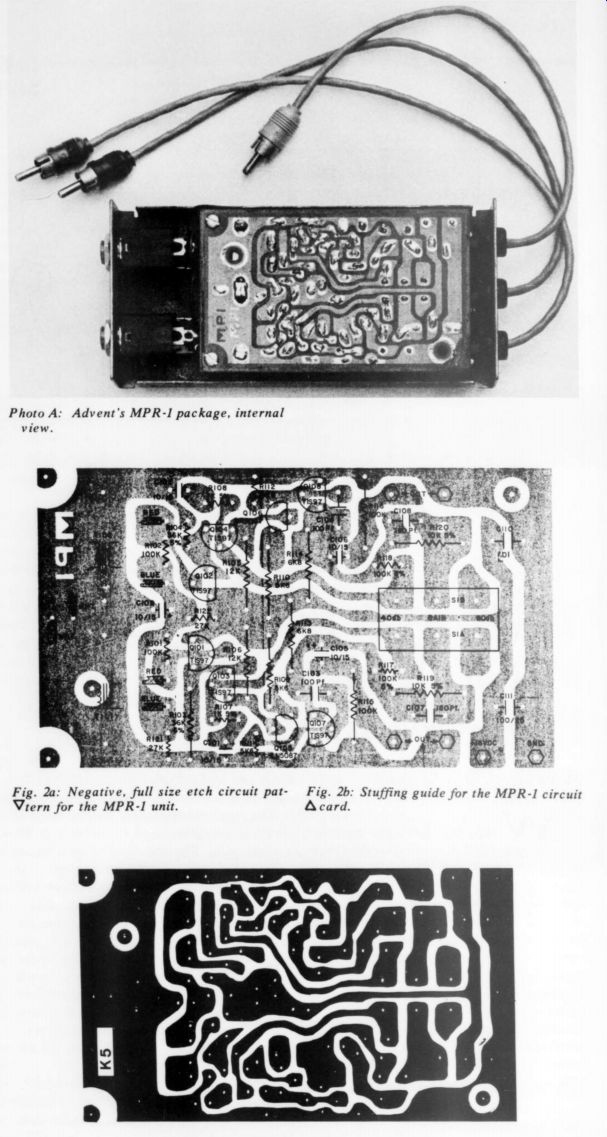
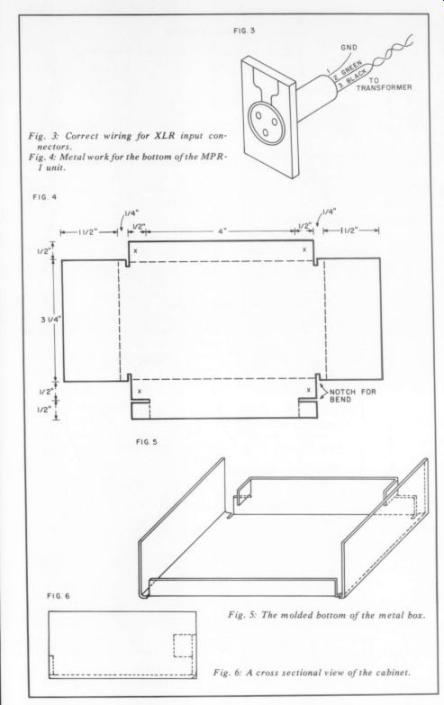
Fig. 5 is a perspective view after bending.
Make sure the sides fall inside the edges of the ends as shown in Fig. 6. The internal ''ears'' secure the batteries. You may want to provide cutouts in the high side to aid battery removal.
A detailed drilling pattern is not provided since dimensions will vary depending on the jacks, gain switch, etc., used. One side of the board boxes in the batteries. There is a close fit between the input jacks and batteries.
The cover is a simple ''U'' fastened to the sides of the bottom with four screws.
Glue some foam to the cover to keep the batteries in place.
PERFORMANCE
-------
TABLE 1
Chan. A
39.5dB 59.4dB
Chan. B
39.5dB 59.5dB
Lo Gain
Hi-Gain
Output Noise (Hi Gain, 20kHz NBw)
Equiv. Input Noise
-60dB .7V -64dB .7V
-119.4dB .7V. -123.5dB .7V
----------------
The output noise measurements are pretty crude because there was a lot of meter ' 'needle bounce'' caused by low frequency noise. While the equivalent input noise is good for a consumer type unit, the better professional mike preamps have some 4 to 8dB lower noise. The output noise should decrease 20dB for the LO GAIN position. The input was terminated with a 270 ohm resistor for the noise measurements.
The MPR-1 is sensitive to magnetic fields. As a rough check of the shielding efficiency of the steel case, I set the preamp on top of my Heath IM-5258 Harmonic Distortion meter. Hum was 15dB lower with the cover in place than when removed. The preamp had to be a foot away from the meter before the hum became unmeasurable. Clearly, care must be taken to position the MPR-1 away from power supplies and other hum sources.
Frequency response is plotted in Fig. 7.
The response will vary for different source impedances (210 ohms was used). The response, while not ruler flat, is fairly decent. Low frequency response can be boosted a bit by increasing C101 and 102-at the cost of more low frequency noise. In a dc coupled preamp, the same transformer was down only 0.8dB at 20Hz and 0.4dB at 70.
Distortion is plotted against output level in Figs. 8 and 9. The apparent leveling off or increase in distortion at low output levels is caused by noise rather than distortion products. The maximum output definitely is affected by the load resistance.
The input impedance of any device fed by the MPR-1 should be at least 10k ohms.
Slew rate limiting is evident at ultra-sonic frequencies. (Dashed lines mean I was too lazy to take enough data to determine the shape of the curve.) The variation of input impedance with frequency is shown in Fig. 10. I do not know what effect the falling impedance at frequency extremes has on microphone output. Some additional investigation is needed here. Phase response is shown in Fig. 11.
CONNECTING THE MPR-1
Much of the material in this and the following section has been adapted from Advent's instruction booklet.
The MPR-1 was designed to work with microphones having an output impedance ranging from 50 to 600 ohms. If your microphones have selectable impedance, use the value closest to 200 ohms. If you have the choice, it is best to use a balanced configuration to minimize pickup of hum, RF interference and other extraneous noise. Be sure all microphone connectors are firmly mated.
-----
Photo A: Advent's MPR-1 package, internal view.
Fig. 2a: Negative, full size etch circuit pattern for the MPR-I unit.
Fig. 2b: Stuffing guide for the MPR-1 circuit card.
Fig. 3: Correct wiring for XLR input connectors.
Fig. 4: Metal work for the bottom of the MPR -I unit.
Fig. 5. and Fig. 6.
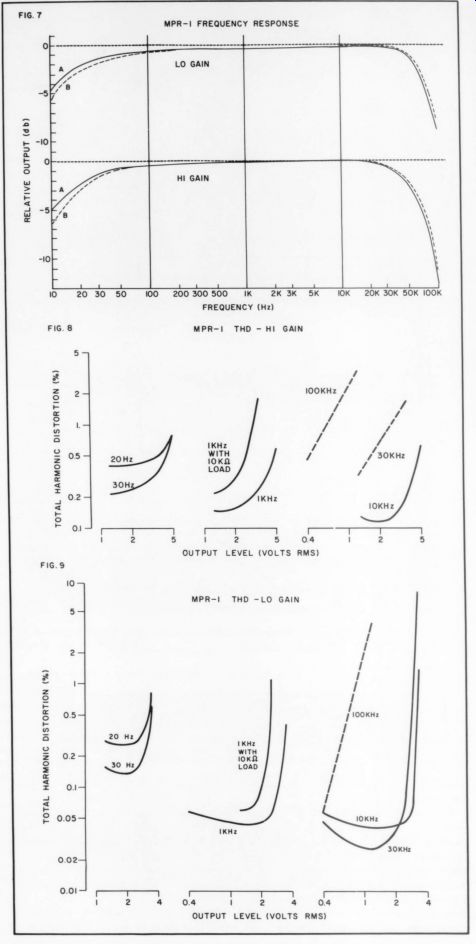
Fig. 7-9.
-----------------------
Balanced Microphone Connection:
The microphone cable should be terminated in a 1/4'' 3-conductor (stereo) phone plug or male XLR-type connector which mates with the MPR-1 input jacks. Connect the wire as follows:
Red to Tip (2)
Black to Ring (3)
Shield to Sleeve (1)
Pin numbers for XLR-type plugs are enclosed in parenthesis. Should your wires be colored differently, the manufacturer didn't observe the standard. In any case, both microphones of a stereo pair should be wired exactly alike to preserve proper phasing. If your mikes don't have two wires, in addition to the shield, they can't be used in a balanced configuration.
Unbalanced Microphone Connection: The microphone cable should be terminated with a 1/4'' 2-conductor (mono) phone plug or XLR-type plug as follows:
Center Conductor to Tip (2)
Shield to Sleeve (1 & 3)
Output Connections: The left and right outputs of the MPR-1 should be connected to the corresponding high level inputs on the recorder or amplifier. Do not connect it to low level microphone inputs as gross overload probably will result.
-------
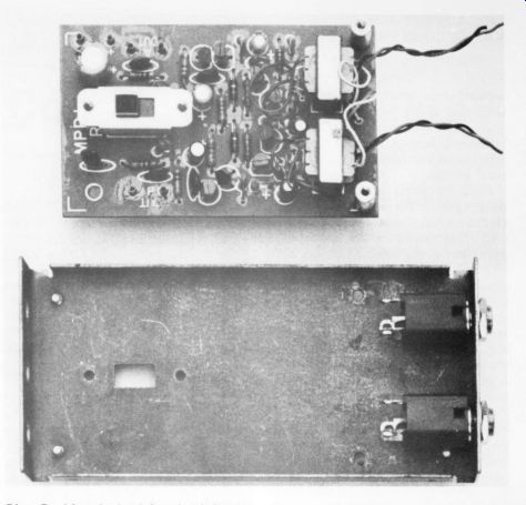
Photo B: Advent's circuit board and chassis. A Note the board mounted gain switch.
Alternate off-board mounting is discussed in the text.

Photo E: Internal view of the author's MPR 1.
------------------
USING THE MPR-1
Proper mike placement depends upon the kind of mikes being used, the acoustic environment, and the particular subjective sound balance you wish to achieve. Experiment liberally with placement, keeping in mind that minor adjustments can have great effect on the tonal balance.
Once the mikes are placed, set the MPR-1 gain switch to 40dB and adjust the recorder's input level controls to give a “0” level indication for sound levels equivalent to the loudest passages to be recorded. Only if it is impossible to obtain the desired volume with the record level controls all the way up should you switch to the 60dB gain position. Do not use the high gain setting unnecessarily as overload may result. Don't be concerned if the record level controls must be quite high to obtain the desired level using the low gain position on the MPR-1.
The peak record level which gives best results depends upon the type of music you're recording. Trial and error is the best way to find the optimum level. If you can't experiment, it's better to err in the direction of slightly under-recording.
Some condenser microphones, usually the professional types, have output sufficient to overload the MPR-1, even set for low gain. Even if this is the case, you may i to attenuate the microphone input. Similar problems may occur when recording voice or brass instruments with extremely close microphone placements.
The MPR-1 gives the live recording enthusiast the opportunity to adapt high quality, low impedance microphones to audiophile recording equipment at moderate cost.
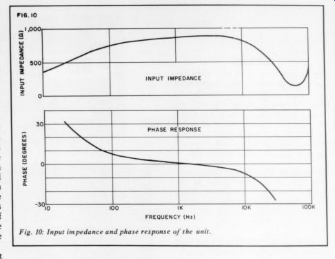
Fig. 10: Input impedance and phase response of the unit.
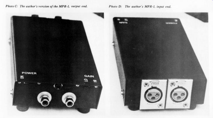
Photo C: The author's version of the MPR-1, output end. Photo D: The author's
MPR-1, input end.
-----
Also see:
Build A Microphone Preamp (Audio magazine, Feb. 1979)
A Comparison of Preamplifier Construction Projects, by S. A. Rossmassler--A reader builds four units with helpful tips