A Comparison of Preamplifier Construction Projects--A reader builds four units with helpful tips.
by S. A. ROSSMASSLER
BUILDING preamplifier / control units for me is one of the most satisfying forms of audio enthusiasm. I can think of at least three good reasons. First, it offers much opportunity for detailed, careful, and involved construction while requiring only a relatively small outlay for parts and materials; second, it allows the builder to provide himself with exactly the type and degree of physical interaction he wants with his audio system; third, the unit is visible when completed, and the builder can literally point with pride to his creation. Of course, like any form of audio construction, building preamplifiers should lead to better sound, too, and the improvement in sound can be expected to track with the quality of construction.
TAA has done well by the tribe of preamplifier builders. We have been offered at least four complete start-from scratch designs, plus any number of modifications and add-ons to existing units. Special attention has been given to the familiar Dynaco preamps. Indeed, as I've been writing this article, Issue number 1, 1978, has appeared, with the exciting remake of the PAT-5 by Jung and White. What more could possibly be needed? Well, perhaps with all these choices available to them, some TAA readers (those who have not yet joined the preamp builders' guild) might like a report on what the water's like, from someone who has been swimming for quite a while. So in the following paragraphs I offer a com parison of several preamp construction projects, involving different approaches and different circuits. I'll emphasize construction, not circuit design, since I have no expertise in the latter area.
However, I will attempt to give some measurements showing results. Finally, I can't resist including a few construction tips based on my own experience-special techniques, precautions, and ways of avoiding trouble.
We could go all the way back to the mid-1950's and start with the WA-P2 monaural preamplifier from Heathkit, but that's really a reminiscence, not relevant to today's needs. Instead, we'll start of with two of TAA 's finest, the Williamson Twin Twenty Preamplifier(1) and the Meyer Super Op-Amp(2). These units give us a chance to explore differing control capabilities, and offer some variety in the completeness of parts supplied to the amateur. This last point may be important to some readers, and I'll come back to it frequently.
WILLIAMSON 20/20 PREAMP
Here the amateur builder can take a big step beyond the total package kits which Dynaco and Heathkit offer. D. and H. just about eliminate any chance of failure. Their 'I will hold your hand' instructions are literally models of clarity. (Since I spend almost half my working hours writing about science and the results of science, I can briefly switch from my amateur hat to my professional hat in order to say that the Dynaco and Heathkit construction manuals contain some of the best, most unambiguous technical writing available anywhere.) But a semi-kit like the 20/20 preamp gives you more learning opportunities. The TAA write up offers enough guidance to almost guarantee success, with plenty of chance to gain practical experience with decisions on chassis layout, choice of switches and potentiometers, selection of hardware, wires and lead placement, grounding practice, etc.
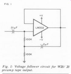
Fig. 1: Voltage follower circuit for W20/ 20 preamp tape output.
I've built two 20 / 20 preamps. The first was intended for a son who needed a versatile To Tape Deck output and had little shelf space. The former requirement led me to add a buffer output stage to the low level To Tape output, coming from the top of the volume control. I used LM302 voltage followers in the recommended circuit from National Semiconductor, shown in Fig. 1. With an input impedance of over 1 megohm, and an output impedance of less than 10 oh ms, it works fine.
The other requirement for this preamp meant | had to bend one of my preamp principles and put the power supply in the same enclosure with the active circuitry.
A surplus library shelf bookend of heavy gauge steel gave me a good internal shield between the transformer and the 20 / 20 high frequency filter.
The second 20 / 20 preamp was for my own use. Since my tape deck has 200k oh m input impedance, I didn't use the voltage follower circuit. But I did tuck all the 60V AC power supply components in a separate enclosure, with a six foot cable and an Electro-Value polarized plug and a matching socket at the rear of the preamp box.
This statement leads me to my first construction tip: always use polarized plugs and jacks for power supply leads. In more general terms, in all audio construction, it's common sense to use different types of connectors for the four categories of inputs and outputs (low level, high-level, DC, and AC). I use RCA plugs and jacks for most low-level signals. They are far from ideal and need repeated maintenance, but they assure compatibility with other components.
BNC connectors are just too expensive.
For certain low-level signals, phone plugs and jacks are obviously desirable if you can afford the space. For low-impedance high level signals, especially speaker leads, I use dual banana-plugs and jacks wherever possible. I never use household connectors for anything except 120VAC.
My 20/20 preamp went together easily and resulted in a compact, smooth handling, versatile unit. The single large circuit-board reduces layout choices, and calls for a convenient-sized enclosure. The Old Colony kit is almost complete, and gives the builder an insight into the world of high-quality parts. The tone controls are gentle, but effective. In the section below on measurements you will find S/N figures for this unit, with some necessary explanations. (The Williamson didn't show up as well as I'd expected!)
SUPER OP-AMP
Dan Meyer of Southwest Technical Products is a long-standing proponent of differential-input configuration preamplifiers. This is quite a different circuit from the 20 / 20 preamp, and apparently provides reduced interaction between the phono cartridge and the preamp. I ordered the 195 preamp stages from SWTP. They come as a partial kit: circuit boards, transistors, resistors and capacitors-no switches or potentiometers.
Instructions are adequate, and of course the TAA article tells the builder why, as well as how, certain things are done. But this unit takes the amateur one step further toward independence and requires quite a bit of planned purchasing. No power supply parts are included (unless you buy the complete 198 kit with enclosure, front panel, etc.). I ordered most of the needed feedback parts and the potentiometers from ElectroValue.
I built my Super Op Amp as a low-level phono preamp only, with switching and volume controls for all sources. There are no tone controls and no second stage of amplification. As the section on measurements will show, the output voltage is lower than on commercially available preamps (I could have gone to a higher voltage power supply to get more output). You can see from Fig. 2 that this preamp, with a separate power supply, is compact. The row of pushbutton switches near the bottom of the front panel provides for many options-monaural operation, choice of two tape inputs, etc.
Bearing in mind the comments of our Editor (appended to the original article), I wired the RIAA contour feedback elements on 1" x 1: pieces of Veroboard, and then stacked the assembly directly above the main boards, held there by two of the resistor leads (Fig. 24). The unit went together easily, except for the push button switches which required rectangular holes. the simplicity of the circuit made for a small number of parts. Performance is excellent, perhaps for the same reason.
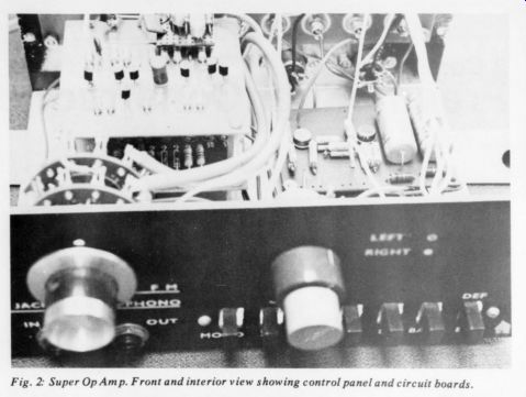
Fig. 2: Super Op Amp. Front and interior view showing control panel
and circuit boards.
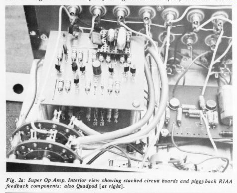
Fig. 2a.
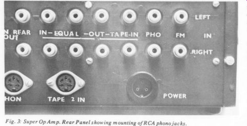
Fig. 3.
Fig. 3 shows the back panel of my Super Op Amp, almost completely devoted to Input / Output jacks. I include this picture because it introduces my second construction tip, which deals with mounting the 10 to 20 or more RCA phono jacks needed for inputs and outputs in the typical preamplifier. One of the joys of home building beyond the ''everything included'' kit stage is the opportunity to do it a little better. Paired and multiple arrays of RCA jacks in commercial kits and even many ready-to-use components are typically cramped, and make for poor contacts. I mount each jack 3/4'' to 1" from all neighbors and have plenty of finger room. Fig. 3 shows the results of the procedure which I describe below:
1. Lay out the spacing for the desired number of left-right pairs of jacks on a blank piece of glass-epoxy (not phenolic) board, 2 1/4'' – 2 1/2” wide, and long enough to suit your needs (4” – 12” in most cases). Pencil a center-line the length of the board, then a pair of guide lines, 0.5" above and below the center line. On these guide lines, mark the location of the jacks at 3/4'' (or 1” if you're feeling generous with space) intervals. Use a square to make sure that the locating points for each top / bottom pair are not skewed. Then mark locations for four mounting holes at the corners of the board (see Fig. 4). If the board is over six inches long, add two extra mounting holes midway along the length for rigidity.
2. Prick punch all hole locations. Drill out the four or six mounting holes with 1/8" bits (for number 4 screws) or 9 / 32"' (for number 6 screws). Mark the top of the board ''Top / rear.''
3. Clamp the board firmly on the outside of the rear panel of the chassis, parallel to the top and bottom thereof. Drill mounting holes in the rear chassis panel, through the mounting holes in the epoxy board.
4. Attach the board to the outside of the rear panel with four nuts and bolts. Remove clamps. Drill 1/4'' holes in the board and the rear panel simultaneously.
5. Remove the board. With your trusty Greenlee punch or your swifter Unibit, enlarge the 1/4'' holes in the rear chassis to 12'. Mount the RCA jacks (with washers and ground contacts) in the 1/4'' holes in the board. Attach the board on the inside of the rear panel with the top up and the "Rear'' side in contact with the panel.
Everything will fit. Only a 1 /16" ring separates the chassis from the body of the jack. No ground loops, because you can wire the grounding leads in accordance with the best principles (3), and nothing touches the chassis until you make it do so.
I included a Quadpod in my Super Op-Amp, and found it added to the richness of sound on some, but by no means all, records. The addition was easy, because I could tap off the main power supply.
Incidentally, the +15VDC power supply was originally built following Dan Meyer's instructions. When I took the unit to a McIntosh Clinic, they reported very low distortion (below 0.01 percent THD) but substantial hum. So I rebuilt the supply, adding two 1000 uF filter capacitors ahead of the specified stages, and dividing the resistance values to give three RC stages. Hum is now very low, as shown in the measurements section.
THE MINI AMP
My next step in increasing builder autonomy came when I decided to build a compact, independent phono preamplifier stage, based on the National Semiconductor LM381A IC. An article by James P. Holm(4) aroused my interest. I wrote to National, and they sent me their book of Applications Notes(5) which I have found valuable for many purposes, including general education. AN-64 and AN-70 provide a full set of equations for tailoring the LM381A feedback circuits to meet any need.
Specifically, I wanted some of the same features that Mr. Holm included-a compact, battery-powered phono preamp with moderate output. My calculations led to values which differed slightly from Holm's (see Fig. 5). The convenience of a battery-powered preamp, only 2” x 4” x 1- 5/8", has made the unit helpful in several emergencies, though I don't use it regularly. I use two 9V transistor batteries, held against the chassis by a short length of aluminum right-angle. The Veroboard circuit is mounted on four standoffs.
My own experience and that of several friends indicates that, while the LM381A is a good performer, it is by no means exceptional in low-noise capability, so I don't see that it could be modified to make a moving-coil preamp. The National Semiconductor Application Note suggests that S / N ratio can be improved by using a single-ended rather than a differential input configuration. However, without the differential input, the input circuit would be affected by the cartridge becoming a part of the feedback loop, and I would also expect somewhat more THD.
The chief interest of this unit is that the parts had to be procured without assistance. This process is full of learning experiences-involving dimensions of capacitors, improvised terminals, etc. It helped me get ready for my next undertaking, which is also the last I'll describe here.
THE LEACH PREAMP
Audio Magazine doesn't have as many good construction articles as TAA, but this one intrigued me(6,7,8,9). In the first place, it tied in with my earlier experience with the Super Op Amp, while promising further refinements: a second differential stage, and an ultra low frequency cut-off. I read the article carefully, and noted that Professor Leach also believes in keeping power supplies in separate boxes (good man!).
I ordered the circuit board and the matched pairs of transistors from the designated source (Components, P. O. Box 33193, Decatur, GA), and the resistors from the Components Center in New York City, a TAA advertiser.
Capacitors came from ElectroValue. By the time everything had arrived, Professor Leach had announced a slight change in a few values. By the time those were obtained, he offered a modified (and obviously much improved) power supply in place of the one I'd just completed. Then some changes in the modified power supply, and further revisions to the low level circuitry.
Now I have the greatest respect for anyone who admits his errors in public, and equal respect for the enthusiast's desire to make everything as close to perfect as possible. But the series of changes in the parts list for the Leach preamplifier brings into the open a difficulty which all audio amateurs face.
Parts are hard to get, and shipping takes a long time. You can't get top quality resistors or capacitors at the hobby electronics stores. You can't buy from the supply houses in ones-or-twos quantities.
Allied (and many other suppliers) have a minimum order fee. By the time I had my Leach preamp put together, I had spent over $200 in Leach-oriented purchases. I have enough parts on hand to put another one together for less than $25, and maybe I will; but the first one was expensive, and took a long time from start to finish.
Incidentally, I'm very pleased with the Leach preamp. It's the best assembly job I've done, and it sounds very, very clean. Measures better than any of the others, too.
GENERAL CONSTRUCTION FEATURES
As noted above, power supplies should be physically separated and shielded from low-level signals. This precaution requires an additional chassis and a connector cable, but it also means that the control unit can be quite compact. If your listening-room decor permits rack mounting of components, the standard 19'' width available means you can mount a preamplifier and some other item side by-side.
Obviously, if you've gone to the trouble of separating the power supply from the preamp itself, you won't want to put the AC on 7 off switch in the preamp box.
Therefore, you are led to mount a total system AC control switch somewhere convenient, and have it control two or more multi-socket AC receptacles.
Choice of chassis units for a preamp usually winds up (for me, at least) with the question ''What size Mini-box is best?'' Mini-boxes are easy to work with, because the two interlocking U-shaped pieces give access to front (for controls), back (for connector sockets), and bottom (for attaching circuit boards, etc.). Only a masochist will choose a closed steel box, with five sides rigidly attached, for a home-brew preamp.
MEASUREMENTS
This whole project is concerned with construction more than analysis of performance, but I did promise some measurements. Lacking THD and IMD analyzers, and without a set-up for taking photographs of oscilloscope displays, I settled on signal-to-noise ratios as one essential criterion for a good preamp. My test gear consists of a medium green IG-18 signal generator and an IM-5238 AC voltmeter.
Even before the Jung and White article in TAA 1/78 p.7, 1 had decided to measure S/N under three conditions:
open input socket, shorted input socket, and with a phono cartridge (in this case, a Stanton 681 EE) attached to the input socket. The basis of comparison was a 10mV, 1kHz sine wave input, with volume control set for 2V output and then not changed. Two units (Super Op Amp and Mini Amp) did not provide 2V out with 10mV input, so I used full output as my basis for calculations. Since the IM-5238 reads directly in dB, the mathematical calculations were within my capabilities. ''Noise'' was taken as the total (unweighted) output with no-signal input.
In order to provide a benchmark of known performance, I also measured my faithful Crown IC 150 preamplifier, and included its performance in the results, which are given in Table 1.
I present these results with some hesitation. It's not surprising to see less noise with shorted input than open input.
But clearly, one channel of the Williamson is sick; perhaps I did a poor job when I replaced a faulty transistor in the input stage during its early history.
-----------------
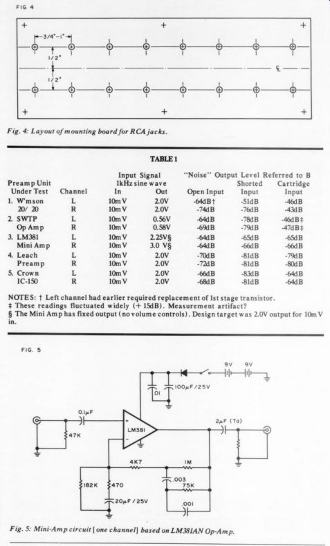
Fig. 4: Layout of mounting board for RCA jacks.
TABLE 1: NOTES: t Left channel had earlier required replacement of Ist stage transistor. These readings fluctuated widely (+ 15dB). Measurement artifact? The Mini Amp has fixed output (no volume controls). Design target was 2.0V output for 10m V in.
Fig. 5: Mini-Amp circuit [ one channel] based on LM38IAN Op-Amp.
------------
Moreover, a 20-30dB increase in noise level with phono cartridge attached to the input (right hand column in Table 1) occurs for three of the units-Williamson, Super Op Amp, and Crown (although the numbers for the Super Op Amp are hardly better than guesses).
These results scream for further instigation, which I propose to undertake.
Was the phono cartridge adequately grounded? Do both channels of the cartridge need to be attached to the preamp? What about different cartridges? Incidentally, my results for the Crown unit with shorted input agree with Crown's specifications and the results of an equipment review of a few years ago (10). This fact makes me feel much better about offering Table 1 for public inspection.
FUTURE PLANS
As I already mentioned, the S/N measurements need to be explored. I feel that in theory the grounding practice recommended by Leach (6) could be improved, but the performance obtained following his instructions was really excellent. Can further improvement be realized in practice? If I can teach myself how to make photographs of CRT sine and square waves without major investment in camera equipment, I'd like to follow up on the present article with some further performance details. In addition, I have two more preamps to build: a two-stage version of the Super Op Amp and a JW revision of the PAT-5. If our revered Editor offers any encouragement, I'll be back in a year or less with Part II covering all of the above.
SUMMARY
I have built four different preamplifiers, starting in each case with a published schematic, but with varying approaches to physical design, layout, and parts acquisition. I enthusiastically recommend all four approaches to audio amateurs.
Scratch building is the most educational way to go, but it costs far more than buying a semi-kit from Old Colony or some similar organization which can save by large-scale purchase of primary components.
REFERENCES
1. Williamson, R., "The 20-20/ Mark II Preamp," The Audio Amateur, Vol. II, No. 2 (1971).
2. Meyer, D., "A Super Op-Amp Preamp," The Audio Amateur, Vol. III, No. 1 (1972).
3. Taylor, P. L., "Grounding in Audio Circuitry," The Audio Amateur, Vol. V, No. 3 (1974). (published February 1975).
4. Holm, J. P., "A Quiet Phonograph Preamplifier," Audio 56:10 (October 1972).
5. Linear Applications, February 1973. AN 64, LM 381 Low Noise Dual Preamplifier; AN 70, LM 381A Dual Preamplifier for Ultra-Low Noise Applications. National Semiconductor Corporation, 2900 Semiconductor Drive, Santa Clara, CA 95051.
6. Leach, W. M., "Construct a Wide Band width Preamplifier," Audio, February 1977.
7. Leach, W. M., "Wideband Preamp Addenda," Audio, April 1977.
8. Leach, W. M., "Leach Preamp Addenda," Audio, September 1977.
9. Leach, W. M., "Wide Bandwidth Preamp Corrections,' Audio, January 1978.
10. "A Great Preamp from Crown International,” High Fidelity Magazine, December 1971.
-----
Also see:
Build A Microphone Preamp (Audio magazine, Feb. 1979)
Audio Aids: by readers Davidson, LeBeck, Sellman, McIntyre, and Philpot
Test Reports: Heath's ID 5252 Audio Load, Heath's IG 1275 Sweep Generator