by Leonard Feldman
Co-channel Interference
Examining the difference between the propagation of FM and AM broadcast signals, we see two outstanding advantages of wideband FM (as presently broadcast) : outstanding fidelity and reduced interference. The term "interference" applies to more than merely "static." It covers any voltage arriving at the input of a receiver or created within the circuitry of the receiver itself which "interferes" with satisfactory reception of the desired station signal.
For a better understanding of FM, we shall therefore next examine the significant forms of interference prevalent in radio broadcasting and show why these forms of interference are less dominant in FM reception than in AM reception.
A frequent annoyance in AM listening (particularly at night, when reception range increases) is the piercing whistle heard when two stations are operating within the same channel.
This whistle is produced whenever the frequency difference between the stations is equal to an audible frequency.
In the case of adjacent channels (10 kHz apart) , the whistle is often eliminated in quality AM receivers by the incorporation of a "10 kHz Whistle Filter." This circuit effectively suppresses all frequencies around 10 kHz without significantly attenuating desired frequencies (5 kHz and below, for AM). In this instance, however, we are discussing Co-channel interference, where two stations (however distant from each other geographically) are occupying the same assigned channel but, because of permitted tolerances, may have carrier frequencies several hundred cycles apart. Since the two carriers are so close in frequency, both signals pass through the circuitry of the AM receiver until, at the second detector, the beat note appears. In typical AM situations, the interfering.
signal will be noticed when it is only Moo as strong as the desired signal.
Contrast this with the 'situation in FM, where, as we shall soon see, the desired signal need be only twice as strong as the interfering signal to completely over-ride it! Fig. 1 represents two r.f. signals, differing slightly in frequency and considerably in amplitude. The resultant waveform (derived by algebraically adding the instantaneous amplitudes of each) is shown in the lower portion of the drawing. You will note that the resultant's amplitude varies at a rate equal to the difference between the two frequencies from which it is derived. If the two frequencies differ by, say, 400 Hz, the amplitude of the resultant will increase and decrease 400 times per second. This AM variation, applied to an AM receiver, would of course be detected in the course of the normal functioning of this type of receiver, producing the familiar "beat note" previously mentioned.
While the effect observed in Fig. 1 may be correctly termed a form of undesired "amplitude modulation," a second, less obvious form of modulation takes place in such situations-phase modulation. That is, with respect to the larger (desired) of the two signals shown in Fig. 1, the added resultant waveform alternately leads and lags by some finite number of degrees. The degree of phase lag or lead depends upon the relative amplitudes of the desired and undesired r.f. signals.
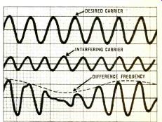
-------- Fig. 1 An interfering carrier added to a desired carrier of
somewhat lower frequency results in the production (af ter detection) of a "beat" frequency.
For illustrative purposes, let us suppose that the undesired waveform is 1/2 as large as the desired signal. Under these circumstances, the phase shift (lag alternating with lead) will amount to 30 degrees. Now, phase modulation is really just another form of FM modulation. In fact, many forms of FM transmitter systems employ simple phase modulation as the first step in the creation of wide-band frequency modulation. So in the context of our analysis, the two terms may be thought of as being synonymous.
To summarize, whenever two signals (close in frequency) appear at the input of a receiver, their resultant will be amplitude and phase modulated. In AM sets, the amplitude variation creates the "beat" or whistle note. The phase modulation adds a small amount of frequency modulation. Both of these new components constitute a departure from the original signal and, in an FM set, must be eliminated. Amplitude variation is by far the simpler to remove. This is done by means of "limiter" stages to which we shall devote considerable discussion in later installments. For the moment, Fig. 2 will serve to illustrate the principles of limiting. Since an FM receiver need sense only changes of carrier frequency, we can, by use of proper circuitry, "slice off" any amplitude variations without removing any desired intelligence from the signal.
The undesired phase modulation is not so easily eliminated. We can quickly show, however, that its effect on performance will be minimal compared with the normal or desired frequency excursions caused by the program information.
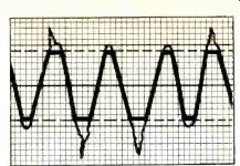
Fig. 2--Limiter circuits in FM receivers "slice off" amplitude
variations caused by all forms of interference. Therefore, the waveform distortion
does not affect the recovered signal.
Using the example cited earlier, it can be shown that if the desired and undesired signal differ in amplitude by two to one and in frequency by 400 cycles, then the indirect FM produced by the resultant phase modulation will be ±200 Hz. That is, the resultant carrier will have an added frequency shift (over and above that caused by normal program material) of 200 Hz above and below the central or nominal frequency. If we compare this shift with the normal maximum deviation of 75,000 Hz authorized by the FCC for wideband FM we see, that the maximum signal-to-interference ratio is 375:1 or better than 50 decibels. To put it another way, this little bit of undesired "FM" interference will be all but inaudible under these conditions.
And, bear in mind, that these conditions, as stated, were quite extreme. It is not usual to have an interfering signal nearly half as great as the desired signal. More typical might be ratios of 1 to 10 or 1 to 20, in which case the effect of the undesired "FM" would be far less.
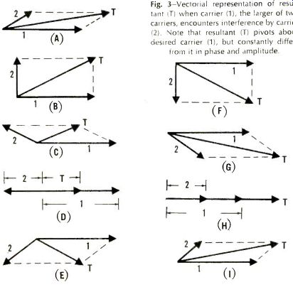
Fig. 3--Vectorial representation of resultant (T) when carrier (I),
the larger of two carriers, encounters interference by carrier (2). Note
that resultant (T) pivots about desired carrier (I), but constantly differs
from it in phase and amplitude.
Strong Signal Domination
A series of vector diagrams, shown in Fig. 3, will help to bring home the concept of "capture" of the stronger of two signals in FM. While the full specification of capture ratio (ability of a receiver to favor the stronger of two FM signals received on the same frequency) depends in part upon certain facets of the receiver design itself, the ability of FM in general to discriminate against an only slightly weaker of two incoming signals is inherent in the FM system, rather than in one given receiver design.
In all of the diagrams of Fig. 3, let us assume that vector 1 represents the desired carrier, "rotating" at 100 mHz.
Vector 2, the undesired signal, is also rotating, but at a frequency of 100.005 mHz, 5,000 Hz higher in frequency than the desired signal. (All rotations, by the way, will be assumed to move counterclockwise.) Since vector 2 is rotating slightly faster than vector 1, it will, in effect, pull ahead of vector 1 as we look at the successive diagrams. The resultant vector, T, will also rotate. If we "stop the action" at various points in the rotation of vector 2 relative to vector 1 and examine resultant T we see that it fluctuates or "wobbles" about vector 1.
In Fig. 3C it has shifted to its maximum position ahead of vector 1, whereas at 3E it has fallen maximally behind vector 1. The back and forth fluctuations of the resultant vector T represent the phase modulation of the resultant carrier. Note, however, that the resultant is wobbling back and forth about vector 1, the larger signal.
Thus, vector 1 (the desired signal) and the resultant vector T have the same average frequency. The signal heard in the loudspeaker of the FM set will be determined primarily by vector 1. If we were to make signal 2 the larger of the pair, the resultant would swing about vector 2, and it would predominate.
Further examination discloses that the amplitude of resultant vector T differs from that of desired vector 1, but we have already stated that these amplitude variations are readily eliminated by means of limiters in the design of the given receiver. The phase modulations of the resultant, while still present, represent a minimal FM deviation compared with the normal program deviation and can therefore be largely ignored. Once the ratio of the interfering to desired signal reaches 1:2, the effect of the smaller signal upon the larger becomes negligible, whether the interfering signal is another, distant station or any other form of random noise.
(Audio magazine, Jan. 1968)
Also see:
AUDIO EQUIPMENT PROFILES (Jan. 1968)
Audio, ETC, by Edward T. Canby
Classical Records, Edward Tatnall Canby
= = = =