University Sound "Studio Pro 120" FM Stereo Receiver
MANUFACTURER'S SPECIFICATIONS
Total Music Power (IHF): 120 watts at 4 ohms, at 0.8% THD. Continuous Power (RMS): 30 watts per channel at 8 ohms, 0.3°/o THD. Power Bandwidth: 10 Hz to 40 kHz, at 0.3°/o THD. IM Distortion: Less than 0.5°/o to rated output. Frequency Response, 1 Watt: 10 Hz to 100 kHz +0, -3 dB. Noise and Hum: Tape monitor, -83 dB; AUX,-80 dB; Phono, -60 dB; Tape Head, -63 dB; all below full output.
Input Sensitivities: Tape Monitor and AUX, 0.4 volts; Tape Head, 1 mV; Phono, 4 mV. Damping Factor: 50:1. FM Sensitivity (IHF): 2.3 microvolts. IF Image Rejection 90 dB. Alt. Channel Selectivity: 55 dB. FM Frequency Response: 20 Hz to 20,000 Hz ± 0.5 dB. FM Stereo Separation: 40 dB at 1 kHz. FM Distortion: Less than 0.5°/o for 75 kHz deviation. Dimensions: 16 3/8 in. x 4 1/2-in. x 12-in. deep. Weight: 17 lbs.
University Sound has been quietly engaged in manufacturing of electronic equipment for military purposes for some years now, but has restricted its consumer activities to transducers until now! With the introduction of its "Studio Pro 120" FM stereo solid-state receiver, the company embarks on a new road.
It has done so with a receiver which, through its excellent performance, functional design, company wherewith all, and price ($379.50), is destined to be a formidable competitor to other receivers.
The Studio Pro 120 does not feature any design breakthroughs in the sense of a radically new device or circuit.
Rather, it incorporates good design philosophy that takes advantage of the state-of-the-art devices and circuits available to engineers. The unit includes 31 silicon transistors (including a front-end MOSFET), 21 diodes, and two of the latest integrated circuits, for example. And starting from scratch, the company was not locked into designs that would be costly to change in one fell swoop. The result is a sensibly arranged front and rear panel layout, a refreshingly handsome appearance, and some extra comforts that will be noted later.
Operated by gold anodized, solid aluminum knobs, primary control functions include the usual selector switch, dual bass and dual treble controls (clutch operated for individual settings of left and right tonal response), balance control, gain control and tuning control. The smooth mechanical action of all of these, including the flywheel action of the station selector, rivals that found in some professional equipment. The front itself is a tasteful, gold anodized, brushed aluminum panel, complemented by a matching anodized dust cover (supplied at no additional cost). As shown in Fig. 1, two walnut side panels (optional at extra cost) may be affixed to "dress up" the unit for open-shelf installation.
Secondary controls are actuated by eight "rocker" switches. These include a speaker-remote switch, MPX, high frequency and low frequency filters, tape monitor switch, loudness contour switch, stereo mono switch, and FM mute switch. All of these switches are arranged so that, in their often-used position, they are similarly depressed. A stereo headphone jack completes the front panel layout.
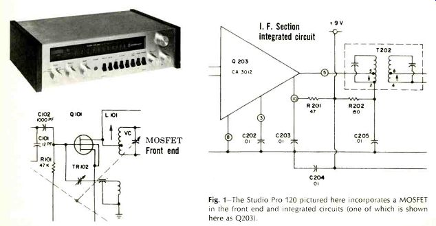
Fig. 1-The Studio Pro 120 pictured here incorporates a MOSFET in the front
end and integrated circuits (one of which is shown here as Q203). I. F. Section
integrated circuit
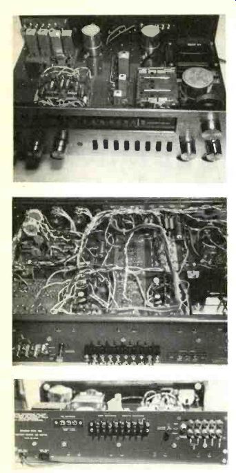
Fig. 2--Silver-plated etched circuit boards, interwired by harnessed wiring,
contribute to the Studio Pro 120's professional appearance with the case removed.
Neat rear panel layout includes a chassis ground binding post for connection
to a turntable's chassis.
The softly illuminated tuning dial area includes a positive-acting FM Stereo indicator light (which during all tests, instrument and listening, was never triggered by interstation noise or any other form of non-stereo interference). An illuminated center-of channel tuning meter, found to be precisely aligned for perfect tuning, is also located on the front panel.
The rear panel, fully as large as the front panel, serves a dual function. It acts as a massive heat-sink for the four power output transistors (which are mounted on the inaccessible side) and provides a mounting surface for an 8 terminal barrier speaker strip, the inputs and tape outputs, a mixed-channel (L + R) output for use with a third channel power amplifier, a convenience a.c. outlet, and FM antenna terminals.
The "local" connection on the antenna strip was found to be superfluous since, in the case of this receiver, 200,000 microvolts of r.f. input applied to the "distant" antenna terminals did not cause even a trace of overload.
The Studio Pro has some welcome conveniences, including three 1 ampere circuit breakers which re-set automatically (two for the speaker channels and one for the power line) and a thumbscrew binding post for connection of a ground lead (for hum reduction) from a turntable base plate.
Circuitry
The completely shielded r.f. section of the receiver consists of a MOSFET r.f. amplifier, followed by a second bipolar transistor r.f. amplifier, a separate converter and a local oscillator, both of which are also silicon units. The FM i.f. section is comprised of two new RCA CA-3012 integrated circuits (each of which does the job of 10 transistors, and a variety of diodes and resistors). A conventional ratio-detector circuit completes the i.f. chain. Multiplex decoder circuitry includes five silicon transistors (one of which is used to actuate the stereo indicator light), two 1N87 diodes in a 38 kHz doubler circuit and four balanced 1N542 diodes in the demodulator bridge circuit.
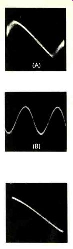
Fig. 3--At only 5 uV r.f. input, sweep alignment response at the tuner's
output exhibits linear trace (A) of over 300 kHz. This accounts for absence
of bandwidth distortion in equivalent resultant sine wave output (B), taken
at 75 kHz deviation. Note that only a trace of noise is evident at this low
level. Quieting is 48 dB at this signal input strength.
Fig. 4 Detector output at 25 AV input and sweep of ±400 kHz is almost perfectly linear, resulting in a distortion figure for FM of only 0.5 % for 75 kHz deviation.
All low-level audio stages feature 2N2712 silicon transistors. A total of sixteen are used for dual preamplifiers, tone control stages (feedback or Baxandall circuit), and low-level amplifying stages. Complementary driver stages for each channel consist of a 2N3053 (NPN) and a 2N4037 (PNP) combination which drives the 2N5037 output pair for each channel. Neither driver transformers nor output transformers are therefore required, resulting in a circuit which was found to be stable at all conditions of loading from open circuit to a 0.1-/2,F capacitor across speaker output terminals.
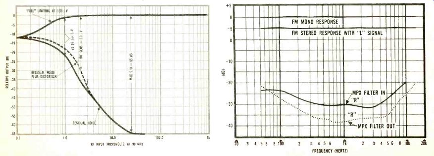
Fig. 5--FM characteristic of the Studio Pro 120 is exceptionally good, requiring
a scale shift to begin at 0.1 AV instead of 1 V. Fig. 6--The upper graph shows
the Pro 120's FM mono and stereo response, while the lower curves illustrate
channel separation.
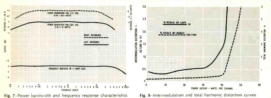
Fig. 7--Power bandwidth and frequency response characteristics. Fig. 8--Intermodulation
and total harmonic distortion curves.
The bridge rectifier power supplymakes available voltages ranging from +56 volts (for the power output transistors) all the way down to +9 and -9 volts. The latter two voltages are zener regulated and are used to power the r.f. section and the i.f. strip.
Five-percent tolerance resistors and capacitors are used in abundance throughout this receiver, particularly in the low level preamplifier stages.
This accounts for the unit's extrefnely accurate equalization and gain between channels. Very low hum levels can be attributed to relatively high values of capacitance used in primary filtering circuits (5000 uF. For 56-volt filtering) and coupling to the loudspeakers (4000 uF) .
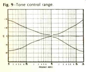
Fig. 9--Tone control range.
Performance
The Studio Pro receiver exceeded its published specifications, often by a wide margin, in nearly every measurement made. Figs. 3 through 6 tell much about the FM performance. While a measured IHF FM sensitivity of 2.3 uV (exactly equal to the manufacturer's rating) tells part of the story, one should recognize that this rating encompasses both residual noise and distortion. As the Studio Pro's r.f. input signal was increased to 5 microvolts or so, however, the FM detector's linear response proved to be so good (Fig. 3A) and so broad (over 400 kHz even at this low signal input) that the recovered audio tone (Fig. 3B), representing full modulation at 400 Hz, exhibited just a touch of residual noise, but virtually no distortion. This is far better (from a listening point of view), than so many cases in which the residual "3%" (or-30 dB) component of the IHF sensitivity measurement consists primarily of distortion. As for "limiting," the receiver may be said to limit on incoming noise, since "full" (3 dB) limiting is achieved at an incredibly low input of only 0.55 uV! The muting circuit does an effective job on muting interstation noise. At the same time, signal inputs as low as 3 microvolts overcome the muting feature.
It should be noted (From Fig. 5) that ordinary 20 dB quieting (without regard to the newer IHF specification) is achieved with an input of 1.0 microvolt (bettering the 1.6 microvolts claimed by University Sound). Total harmonic distortion for 75 kHz modulation is less than 0.5%, at all signal levels exceeding 25 microvolts, thanks in part to a wide-band detector response (shown in Fig. 4) which is almost perfectly linear for about 800 kHz.
As for FM stereo separation, the unit tested missed the 40 dB spec by only 2 dB, but this is a moot point.
More important than this reading, which in itself is excellent, is the fact that at least 25 dB of separation is maintained at all frequencies from 20 to 10,000 Hz (see curve of Fig. 6).
Mono and stereo FM frequency response held to the 0.5 dB claimed by the manufacturer.
In high quality FM stereo units, circuit design to reduce reception of SCA broadcasts (background music via multiplex, on a station simultaneously engaged in stereo transmission) often leads to some degradation of separation capability, particularly at high frequencies. University Sound has wisely elected to reject SCA minimally, under normal conditions, since only a few stations engage in this additional, private subscriber service. When a station broadcasting SCA is encountered, however, some interference is noted. But this can then be attenuated by activating the MPX filter mentioned earlier.
In this way, optimum separation is maintained for all stations broadcasting only stereo, while minimal reduction in separation is introduced by the filter to reject SCA interference properly for the few stations engaged in this form of broadcasting.
Additional FM specifications that were confirmed by measurement include a capture ratio of 1 dB and an alternate channel selectivity of 58 dB (the manufacturer boasts only 55 db)
and FM cross-modulation rejection of better than 95 dB. Curves and measurements tell much about equipment, but for the evergrowing number of FM-DX'ers, suffice to say that the Studio Pro 120 pulled in 38 perfectly listenable FM stations in the New York City area (of which 13 were broadcasting in FM stereo) on a simple, home-made dipole antenna tossed casually behind the receiver.
This means that many of the stations were separated by only one channel width (200 kHz); yet there was no difficulty in isolating one station from the next, nor was there the slightest audible evidence of co-channel interference.
Amplifier measurements
Though University Sound rates the continuous power per channel at 30 watts and 0.3% distortion, instrument readings obtained were 30 watts at 0.2% THD into an 8-ohm load. Not surprising, the stereo amplifier section is capable of a good deal more power out, so in plotting power bandwidth (Fig. 7), two curves are given. The lower curve is taken for 0.3% THD and corresponds almost precisely with the specifications listed earlier. Since less-conservative manufacturers usually specify a 1.0% THD figure, a second bandwidth plot was made based on this higher distortion figure. The results indicate a power bandwidth of 15 to 35,000 Hz, at 40.5 watts per channel. Curves of IM distortion and THD (for 1 kHz) are shown in Fig. 8.
Tone control range is shown in Fig. 9. Mechanical centering of the tone controls corresponded accurately with uniform or flat electrical response.
Loudness compensation is so arranged that, with the loudness circuit in, a boost of approximately 10 dB at 100 Hz is provided at 1/4 rotation, whereas at 1/2 rotation of the gain control, compensation is about 6 dB at 100 Hz. Under actual listening conditions, the loudness action here seemed a bit exaggerated. But many listeners do like enhanced bass and, in the final analysis, the loudness control can be turned off and the individual bass controls used for any degree of compensation.
Using a medium-output phono cartridge to check phonograph performance, levels corresponded nicely with the internal FM audio output, obviating the need to juggle the gain control every time the selector is switched from one mode to the other. As for phono and tape equalization, a plot was taken for comparison with RIAA and NAB (71/2-in.) equalization standards, but since deviation never exceeded 0.2 dB, the "curves" appeared as a straight line! Phono hum and noise was less than that specified, measuring 68 dB below full output, referenced to a 5 millivolt input signal at 1 kHz. Aux hum and noise measured 90 dB below full output, a parameter normally associated with separate power amplifiers rather than all-in-one receivers.
Conclusion
Instrument readings never tell the whole story, of course, even with electronic componentry. There are still intangibles for which measurements have not yet been devised. Further, when dealing with readings in the vicinity of 0.1 and 0.2, tolerances of test instruments become significant factors. Consequently, one must live with a product under normal listening conditions for a while. This was done, some for sheer pleasure rather than pure evaluation.
The Studio Pro 120 handled all forms of source material effortlessly in a medium-large living room that has a fairly nice acoustic setting. Using a pair of highly respected, low efficiency speaker systems, the hi-fi stereo system (incorporating the Studio Pro 120) reproduced sound with matchless clarity. Percussion attack was beautiful to hear: crisp, sharp, absolutely clean, no muddiness-take your choice of adjectives.
There is no doubt that this receiver has a superlative audio amplifier. In fact, it's the peer of many separate amplifiers in performance quality.
Coupled with an excellent FM tuner, and priced at $379.50, University Sound has made an auspicious entry to the component receiver field. Considering its performance, compact size, and cost, and ignoring the absence of some professional features such as step-type tone controls, output level adjustments for each input, etc., the Studio Pro 120 certainly lives up to its name.
HAMMOND M-100 CONDENSER MICROPHONES
MANUFACTURER'S SPECIFICATIONS: Omnidirectional condenser microphone with Nuvistor preamplifier. Frequency Response: 20 Hz to 22 kHz, ±3 dB. Sensitivity, 2 mV/p, bar. Output impedance, 60 ohms. Power supply operates from 117-V. a.c. line. Microphone size, 13/16-in. dia. x 4-in. long. Power supply/carrying case, 4-in. x 4-in. x 12-in.
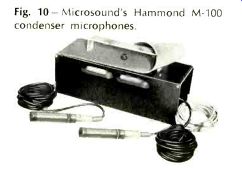
Fig. 10 Microsound's Hammond M-100 condenser microphones.
Here is a condenser microphone at a price which makes it possible for the average individual to own one, not just the professionals. Or even to own two, since the price of a pair of Hammond M-100's, together with the power supply, is $229.50. Single, the microphone costs $149.50 with the power supply.
Considering the relatively low price of these microphones, one might be doubtful of the quality. But an inspection should relieve that doubt. The microphones are small and neat, and attach to their Cannon connectors with hardly any noticeable difference in diameter. (Now if the plugs were only black....) The grille is a part of a machined aluminum housing, with the slots covered by a mesh to keep dust out of the diaphragm area. The power supply is built into the carrying case, and all cables can be accommodated in spaces at the ends of the case. These cables consist of two 15-ft. microphone cables, two 9-ft. shielded audio output cables, and the a.c. line cord, also 9 ft. long. The case is a single piece of aluminum bent in the form of a U, with the housing for the power supply in another U which occupies the center portion of the case. Two aluminum tubes are attached to the second U to hold the microphone bodies, thus serving to protect them, store them, or to provide a carrying compartment for them when going out in the "field" for a recording session.
We ran our usual comparison tests with a calibrated condenser mike of another make to determine the frequency response, and found it to be very close to the specifications-as close as such measurements can usually produce in other than an anechoic chamber. The comparative curves are shown in Figs. 1 and 2, the latter being the polar characteristic.
Aside from the human voice, crackling cellophane, jingling keys, and such other "live" sounds, we were not able to do much live recording with the M-100's. However, using reproduced music over a good system, we found that they would take a 95 dB SPL without overloading, and upon playing back, the reproduction was scarcely indistinguishable from the source. Putting the microphones outdoors simply brought the outside sounds right into the house, with birds and automobiles flying by right in the living room. Children playing on the street might as well have been inside as far as the sound was concerned.
The power supply is neatly made, employing a sturdy transformer, three transistors, and a VR tube on a generously sized etched circuit panel. Our major criticism was the arrangement of the power switch. In the usual British fashion it pushed down to turn on.
American users might well want to rotate it 180 deg. so it turned the power on when it was pushed up (we did). Several interesting ideas were employed in making the power supply/ carrying case, all of which serve to reduce costs, and the savings are passed along to the user. The frame of the case, as described previously, consists of the 4" x 4" x 12" U-shaped structure, with the power supply occupying the center 7-in. compartment. A sturdy strip of aluminum is attached to the power supply housing and serves as a handle and as protection for the pilot light which is located underneath it. A 20-in. strip of rubberized cloth material is held in place by the pilot light mounting and extends over the top of the case and down the open ends of the U-shaped structure. Metal ends are pressed onto the rubber material and catch under notches on the ends of the housing, eliminating a built-up case, fasteners, hinges, and the like, and yet performing like a proper case for the entire assembly.
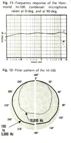
Fig. 11-Frequency
response of the Hammond M-100 condenser microphone taken at 0-deg. and at
90-deg. Fig. 12--Polar pattern of the M-100.
A minor low-end rolloff is provided, since like any good condenser microphone, the low end response is practically to d.c. unless some reactances are provided in the output coupling circuitry. This rolloff results from the use of a 400-uF, 4-volt coupling capacitor between the cathode of the Nuvistor and the output lead. This should provide a 3-dB rolloff at 7 Hz, when the unit is working into a 50-ohm load, which is hardly noticeable at all. For a higher rolloff frequency, this capacitor could be changed, and in fact, it should be, probably, when working into a high impedance circuit.
The microphone circuit is conventional, except for the use of a Nuvistor instead of an ordinary vacuum tube. This does make possible the use of smaller microphone cases, however. The signal is developed across a 92-Megohm load resistor by the condenser head, and is fed to the grid of the Nuvistor through a small capacitor without a grid resistor. The plate is fed with approximately 105 volts, while the polarizing voltage to the condenser head is somewhat higher.
The cathode is led to ground through a 1200-ohm resistor, and the output coupling capacitor connects to the cathode. One heater lead is grounded, while the other is fed from the regulated supply.
The multi-lead cable which connects to the microphone carries five leads, and may be extended to a maximum of 200 ft. An adjustment is provided in the power supply to increase the heater current to maintain proper operation in case the lead is extended to greater than 50 ft.
Output from the microphone is sufficient to feed practically any tape recorder or amplifier provided with a microphone input. Many recordists will find that they will obtain improved results when they employ the M-100 in place of dynamic or ribbon models they may now be using. We would like to see these units provided with cardioid heads which could be interchanged with the omnidirectional ones which are (apparently) not removable. However, there are plenty of uses for the omni pattern, and the M-100 certainly provides the recordist with the much desired condenser microphones at a price that still lets him buy a better tape recorder, assuming he is working with a fixed total for his recording system.
Also see:
Stereo Discs: 10 Years Old Stereo Disc Cutting, by Albert B. Grundy (Jan. 1968)
Further Adventures of a Sound Purist, by John W. Linsley
= = = =