by Albert B. Grundy
Stereo Disc Cutting
ALBERT B. GRUNDY
THE STEREOPHONIC RECORD WAS introduced over 10 years ago (at the October 1957 Audio Enginering Society Convention) . Through these years, many articles were published about the method of obtaining two independent channels in one record groove. Nevertheless, many aspects of stereo groove cutting still remain a mystery to many audio buffs, including a host of recording engineers.
Disc cutting heads and cutting systems have an undeserved reputation of being the most temperamental part of any studio operation.
Engineers often blame the system when results obtained at previous times cannot be repeated. More often than not, this is due to a misunderstanding of what happened the first time.
Tape recording has driven most "instantaneous" disc recording out of existence; the only commercial application left is cutting master records for disc production. In fact, today there are only two European firms (Ortofon and Neumann) and one American Company (Westrex) manufacturing mastering-quality mono and stereo dynamic cutter heads. One other mono cutting system, Grampian, is also used for mastering. It is a magnetic system as opposed to a dynamic system; that is, it has a stationary coil and a moving iron armature rather than a coil moving in a magnetic field.
It is of great benefit to understand how mono grooves are cut before tackling stereo grooves, so let us examine the earlier system first.
Monophonic grooves
Specifications for groove geometry and dimensions are given in great detail in the NAB and RIAA standards for disc recording and reproducing and are, in general, well known to most engineers. That is, static dimensions: depth, width, bottom radius and included angle.
And professionals experience no difficulty with lead-ins, spirals, and lead-out grooves. But this is not always true of some of the groove's dynamic characteristics, such as, peak amplitude or velocity in centimeters per second. What happens during modulation is really what we want to know. Not only is the disc moving with turntable rotation, but the stylus is actually in motion perpendicular to the groove.
One other concept that should be clarified at this time is groove velocity or peripheral groove speed.
The peripheral groove speed is the rate (usually in inches per second) at which the disc passes under the stylus. Since the rotational speed of the turntable is a constant 33% rpm or 1.8 seconds per revolution, the length of groove passing the stylus in one revolution is a function of the instantaneous radius that is being cut.
As the stylus moves toward the center of the disc the radius becomes smaller. Consequently, the length of groove that passes the stylus in one revolution becomes progressively less. The circumference at the beginning diameter of a standard 12-in. LP is approximately 36 inches.
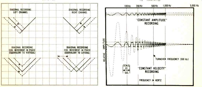
Fig. 1-Cross-section of 45°/45° stereophonic disc shows recording extremes. Fig.
2-Wave patterns of "constant amplitude" vs. "constant
velocity" recording.
Groove speed, based on the foregoing 1.8 seconds per revolution, is therefore 20 inches per second. By the same reasoning, groove speed at the RIAA minimum closing diameter is 8.3 inches per second. With modern cutting heads, this variation in groove speed has very little effect on the recording process. It simply means that the packing density of information is about 2.5 times as great as the inner diameter. Its effect really shows up in playback when we try to recover this information. A cutting stylus for monophonic records moves laterally with respect to the plane of the disc surface. In other words, it is actually on the disc radius and instantaneously perpendicular to the rotational motion of the groove.
The motion of the stylus and, therefore, the dynamic characteristic of the groove, is most easily examined with sine wave modulation.
When the cutter head is driven by a sine wave, the stylus moves from side to side in a straight line. The stylus moves from its center rest position to one extreme, stops, reverses its direction, and moves back through the center position to the other extreme, stops, and repeats the pattern. When the disc is rotating, this motion is stretched out in the form of an undulating groove which has the appearance of a conventional sine wave. The distance that the stylus moves from the rest position to the extreme position (where it stops and reverses its direction) is called the peak amplitude; the distance between the two extremes, which is simply double the one-side distance, is called the peak-to-peak amplitude. This peak-to-peak amplitude actually determines the total over-all width of the groove. Since there must be some space between adjacent grooves, a certain land area must be allowed. The total space allowed for each groove must therefore be the sum of the peak-to-peak amplitude of the groove and the width of the land.
The stylus velocity is the rate at which the stylus moves back and forth in the groove. This can be either the cutting stylus or the playback stylus. All dynamic cutter heads and pickups are velocity-sensitive devices or transducers. The pickup transforms the mechanical motion of the groove into a voltage at its output terminals according to the general law: E = BLV In this equation, the B is the magnetic field strength of the permanent magnets in the cutter head or pickup, and the L is the length of wire in the coil. For any pickup or cutter head, these two factors are fixed.
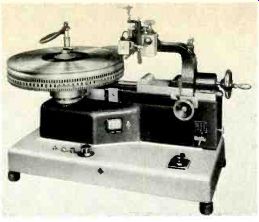
Fig. 3-Example of a disc mastering lathe, the Neumann
AM-131, shown with a Neumann ES-59 mono dynamic feedback cutterhead mounted.
Therefore, the equation can be simplified to: E + KV The output voltage, E, of the pickup is directly proportional to the velocity, V, of the stylus and, in the cutter head, the stylus velocity is directly proportional to the driving voltage. (K is simply a constant.) The stylus velocity will be a sinusoidal function if the cutter head's driving voltage is also a sine wave.
The stylus moves from the center rest position to one extreme end.
And it must slow down to zero velocity when it reaches this end to reverse its direction. It starts to move in the opposite direction, accelerating until it passes through the center position and then slowing down so that it stops and reverses again at the other extreme limit of motion.
It should be obvious from this that the stylus reaches its peak velocity at the moment it passes through the center position. Since the stylus has to stop and start in the opposite direction at each extreme limit of motion, its velocity is constantly changing. Accordingly, the expression "stylus velocity" must refer to some particular instantaneous velocity.
This is, as mentioned before, the velocity of the stylus when it passes through the center position. It is at this position that the maximum driving voltage to the cutter head is required. And it's here that the pickup produces its maximum output voltage. From this it can be seen that stylus velocity is actually a measurement of the level on the disc. The higher the instantaneous stylus velocity, the higher will be the output from the disc.
The direct relationship between stylus velocity and stylus amplitude is really very simple. One other factor must be considered: the number of these back and forth motions that the stylus must make in any given amount of time. This is, naturally, the frequency of the signal being recorded. If we start with something simple like 1000 Hz, we know that the stylus must make 1000 of these back and forth trips in one second.
How far it can go (amplitude) is a function of how fast it must go ( velocity) . At a frequency of 1000 Hz, the stylus has .001 seconds to complete each trip. If we make it move faster it can go further in this amount of time than if it moves slowly. The amplitude is directly proportional to the velocity and indirectly proportional to the frequency. For example, at 100 Hz the stylus has .01 seconds to complete each trip. This is ten times as much time per trip.
If it is to maintain the same velocity it must travel ten times farther per trip to use up the allotted time per trip.
If a simple constant-velocity cutter head is fed a constant voltage and the frequencies varied, the amplitude must vary from very high at low frequencies to very low at high frequencies, in accordance with the expression A=V/ 2 pi f.
The most important factor that determines just how much amplitude can be cut is the required playing time of the disc.. If 12-inch LP's were cut to play only five or ten minutes, they could have big fat grooves with large amplitudes and, therefore, a very good signal-to-noise ratio. The only limiting factor would then become the size of the playback stylus. Since this is generally fixed, there is a limit to just how large the groove can be. As most LP's have twenty to thirty minutes of playing time, the available space on the disc itself limits the amplitude of the grooves.
For a 12-inch 33 1/3 disc to play twenty-five minutes and stay within the standard maximum and minimum diameters, the pitch of such a disc must be 250 lines per inch. The reciprocal of the lines-per-inch figure is the number of inches per line (always a fraction). This is a measure of the total space available for the peak-to-peak groove amplitude and the land width. For a twenty-five minute disc this groove space is 0.004 inches.
That seems like an awful lot of space considering that, at the standard peak stylus velocity of seven centimeters/second at 1000 Hz, the peak-to-peak amplitude is only 0.0022 centimeters or 0.00087 inches.
But the audio frequency spectrum is incredibly wide; the conventional range from 20 Hz to 20 kHz is about 10 octaves wide. Considering that constant-velocity devices--dynamic pickups and cutter heads--have an amplitude that's inversely proportional to frequency at a rate of 6 dB per octave (that is, if you halve the frequency, you double the amplitude), this would mean for the above-chosen 7 centimeters/second velocity at 1000 Hz and the resultant amplitude of 0.00087 inches, that the amplitude at 20 Hz would be 0.044 inches and 0.000044 inches at 20 kHz.
Both these extremes are obviously impossible. Something's got to give! At the low end, the available groove space couldn't possibly accommodate such excursions. At the high end there is plenty of room available in the groove space for wider excursions, but noise is the limiting factor.
To overcome these limitations, we must modify the system to restrict the amplitude of excursion in the low-frequency part of the spectrum and to increase the amplitude at the high end. This is done by recording equalization. The amplitudes in the low end are limited by changing the cutter head's characteristic at 500 Hz from constant velocity to constant amplitude. This frequency is called the turnover point. The level of the voltage driving the cutting stylus, and therefore the cutting stylus velocity, is rolled off at a rate of 6 dB/octave. The normal rise in amplitude of 6 dB/octave with lowering frequency is thus exactly balanced and the amplitude remains constant. All this is shown graphically in Fig. 2.
Above the turnover point, the voltage driving the cutter head, therefore the stylus velocity, is increased with frequency. This produces an almost constant amplitude characteristic, as in the low end. This lifting of the level above the turnover is called pre-emphasis. The resulting recording characteristic is the exact inverse of the standard RIAA playback characteristic. (Actually, the recording characteristic is controlled by geometry, and the RIAA playback characteristic must compensate for it.) There is a third section or time constant in the RIAA characteristic in addition to the high end pre-emphasis and low end constant amplitude time constants. This provides for a slight increase in the recorded level in the very low bass end so that turntable rumble will be somewhat reduced in playback.
Stereophonic grooves
Standard stereophonic grooves are cut with the 45-45 degree system originally described by Blumlein so many years ago, now called the Westrex system. The unmodulated grooves are identical to today's standard monophonic grooves. Because of the adoption of smaller-radius playback stylus tips (0.7 and, recently, 0.5 mil) for stereo cartridges, the minimum dimensions of stereo grooves can be somewhat smaller.
The left and the right channels are recorded each at 45 deg. to the surface of the disc. The motion of the cutting stylus for each channel is basically the same as that in mono recording. The stylus tip moves along a straight line at an angle of 45 deg. in mono recording; this straight line is parallel to the surface of the disc. When the stylus moves along this 45-deg. degree line, its movement is somewhat side to side and somewhat up and down. More technically speaking, there is both a lateral and a vertical component of stylus motion. The second channel is recorded in exactly the same way, except that the line of stylus motion is tilted at 45 deg. in the other direction, making an angle of 90 deg. between the two lines of motion. The resultant stereo groove is thus a combination of both lateral and vertical motion.
If the two channels of the cutter head are fed identical signals, the vertical components will add together and produce a vertical motion of the cutting stylus twice as great in amplitude as would be obtained by feeding one channel alone. The lateral components are also equal, but in opposite directions, so that they cancel one another. Obviously, there is no resultant lateral motion.
In case the two channels are fed out of phase, just the opposite occurs--the vertical components cancel and a purely lateral or monophonic groove is cut. These relationships are shown graphically in Fig. 1.
In most stereo tapes, the bass frequencies (from approximately 200 Hz on down) are in phase. This is true of conventional recording techniques, but not necessarily true where extremes of separation are attempted. It is desirable to have this in-phase or mono information appear as lateral modulation, primarily because stereo records are sometimes played with a mono cartridge. To achieve this lateral motion for in phase signals, one of the channels in the cutter head is reversed in phase by the manufacturer so that mono signals may be fed in phase to the cutting channels. From this it can be seen that, for composite stereo signals, all information that is in phase from the two channels appears as lateral modulation and all signals that are out of phase produce vertical modulation. The lateral modulation is produced by the sum of the right and the left channels, while the vertical modulation is produced by the difference between them.
Another way of looking at the whole picture is that mono is merely a special case of stereo where the left and right channels are identical.
It is common practice today to cut mono records with stereo cutting systems. This requires top-quality stereo cutting systems in which no vertical modulation results from cutting channels being driven in phase. It is clear that it won't be long before strictly mono cutting systems become a thing of the past.
(Audio magazine, Jan. 1968)
Also see:
Stereo Disc Playback, by Charles R. Doty, Sr.
ADC Stereo Cartridge 10E MK IV (Equip. Profile, Dec. 1972)
= = = =