In the November issue of AUDIO I note a letter concerning my recent article about a stereo limiter.
I appreciate the writer's comments concerning separate limiting of stereo channels. It is true that separate limiting of stereo signals can lead to "wandering stereo images," particularly when the signals are continually "processed." Our design philosophy was given in a previous article (AUDIO, September 1965, p. 50) as follows: "It should be emphasized that this device is not intended for use as an automatic gain-riding circuit in stereophonic applications. It was designed solely to eliminate or to reduce occasional overloading during the recording of amateur performers whose decibel cannot always be accurately predicted.
For this use, and for this use alone, this arrangement is recommended."
DR. WAYNE B. DENNY; Grinnell. Iowa
I read with interest the article by Wayne B. Denny in your September issue. First, let me point out that in 1961 I built a similar device and applied for a patent. In 1965 patent #3185936 was issued covering the device. My device had an additional feature whereby the function of the unit could be reversed, thus allowing re-expansion of the compressed signal on playback.
The author describes the action of his device as symmetrical clipping; I hope this is not the case as this would introduce great amounts of distortion.
I think the action is better described as an automatic gain control or volume compression. I would like also to point out that in his Fig. 4 the symbols he uses for the amplifier modules are backwards from the usual practice.
I think that the author greatly limited the usefulness of the device and gives the reader a few wrong impressions.
1. "The operator has no control over the signal level at which limiting will occur." This can be cured by placing gain controls between A3 and A5 and also between A4 and A6.
2. "... nor can he change attack and release times of the control circuits." .. but this would greatly complicate the circuit." Mr. Denny also gives one the impression that "'RC' time constant" circuits are complex above the reader's comprehension. This is no more so than would be loudspeaker crossover networks.
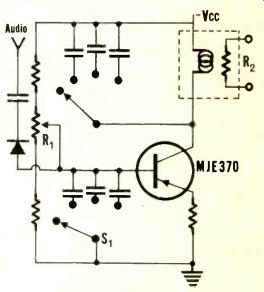
The circuit for driving the lamp shown below overcomes all of these disadvantages and more.
In this configuration the use of the bias control R1 and the elimination of the output transformer allow the lamp to be biased slightly on. This is adjusted so that the value of R2 under no-signal conditions is somewhere between 1 meg and 500K ohms. This allows for a much faster attack time because the lamp does not have to overcome the thermal inertia of the cold filament.
The addition of S1 and its associated capacitors gives the variable release time while S2 and its associated capacitors give the unit variable attack times. If, at the builder's option, the diode, S1, S2, and their capacitors are eliminated, the circuit will still be less complex and slightly more flexible than Mr. Denny's circuit.
The control element may be more economically made from a suitable pilot lamps and CdS photocell enclosed in a short length of heat-shrinkable tubing. The use of the inexpensive MJE370 transistor eliminates the need to parallel smaller devices.
STEVEN B. FULLER; Webster Groves, Mo.
The term "symmetrical clipping" is unfortunate. The device does not clip, symmetrically or otherwise, and did not appear in the original manuscript.
Certainly the operation of the limiter can be improved as suggested. However, it was the author's purpose to provide a device for use by nontechnical personnel concerned with the recording of local (mostly student) groups. At present they are required merely to preset the recorder gain controls so that limiting starts at 0 VU (approximately). Gain is then controlled at the limiter.
The suggested scheme for control of attack and recovery time constants is attractive; it is planned to lengthen the recovery time in the manner shown.
-Ed.
In the printed circuit layout shown in Arthur Gladfelter's "Solid State Flutter Meter" (Ammo, March-June, 1966), C27 is completely short-circuited and the input side of R29 (which should connect half of the discriminator to Qs) is instead connected to signal grounds. The necessary changes are far easier to make before the circuit boards are etched than through trouble-shooting procedures after construction! Credit for their detection must be given to Mr. John Hanna, Director of Audio Visual Aids, Lake Erie College.
There are two further errors of lesser consequence: (1) the meter-protecting diode is shown in the the circuit diagram with polarity reversed; (2) readers will search the Allied catalogue in vain for a power transformer matching the description given in the parts list. It is in fact listed as a "low-voltage rectifier transformer," a multi-tap unit described as " 10-20CT-40CT." Despite these, AUDIO is to be commended for presenting Mr. Gladfelter's excellent instrument, the more so since this crucial piece of equipment is absent from the catalogues of the major kit manufacturers.
CRAIG L. STARK, Painsville, Ohio
In the August 1967 issue, Audioclinic was way off base on "Power Output vs. Impedance." Part of the answer was, . an impedance change of 100% above or below the optimum impedance of a solid-state amplifier will decrease power by about 25 to 35 percent." The fact is that in direct-coupled (transformerless) solid-state amplifiers an impedance increase of 100% decreases power output by about 35%. But a decrease in load impedance of 50% will increase power output as much as 40%. These figures depend mainly on power supply regulation, but also on feedback, among other things. Also note that you cannot have a decrease of 100% or you are left with zero!
RALPH HARTZ; Hazlet, N. J.
(Audio magazine, Jan. 1968)
Also see:
AUDIO EQUIPMENT PROFILES (Jan. 1968)
Audioclinic, Joseph Giovanelli
= = = =