MANUFACTURER'S SPECIFICATIONS:
Continuous RMS Power Output: 150 watts per channel, with 8 or 4 ohm loads, both channels driven from 20Hz to 20 kHz, with 0.1% or less total harmonic distortion.
IM Distortion: 0.1% at rated power, SMPTE.
One-Watt Frequency Response: 5 to 100 kHz, +0,-1 dB.
Power Bandwidth: 5 Hz to 50 kHz, 0.5% distortion.
Hum and Noise: 110 dB.
Damping Factor: 100 at 1 kHz, 8 ohms.
Input Sensitivity and Impedance: 0.775 V, 50k ohms.
Weight: 95 lbs.
Price: $1600.00; UC-1 control unit, $250.00 (optional).
The Yamaha B-1 is one of a new breed of amplifiers from Japan using vertical field-effect transistor (V-FET) output devices. The unit is beautifully made, solidly constructed, and very heavy, weighing about 95 lbs. The UC-1, a companion control unit with peak-reading power meters and speaker switches, adds another 14 lbs. After moving this amp about several times, this writer would recommend a small crane or fork lift for prospective owners.
The chassis has two heavy side pieces with a sub-floor between for most of the front-back distance. Power transformers and filter capacitors are bolted to this sub-floor, along with PC and other connectors for all the sub-assemblies including two output-device heat sinks and one power amp drive board per channel, two regulator boards, a protection board, another large heat sink with 6 regulator transistors and several power resistors, the front panel chosen, and finally the input amplifier and filter board. The output device heat sinks are rather large and the output devices themselves are in a large case-about 50% larger than the usual diamond-shaped TO-3 output device. The wiring is neat, and workmanship excellent. The standard front panel insert takes about 30% of the height, starting at the bottom of the front edge, and is horizontally grained, clear anodized aluminum, contrasting with the black remainder of the amp.

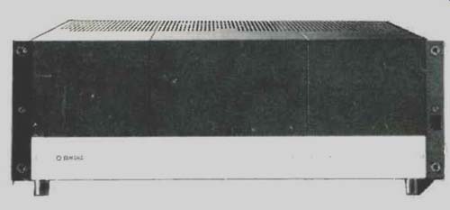
Fig. 1--Rear of the Yamaha B-1 amplifier.

Fig. 2--Interior of the B-1 amp.
Controls with the standard insert are a pushbutton main power switch and two output level controls. Three light emitting diodes (LEDs) indicate Power On, and either Thermal or Overload Protection circuitry activation.
The UC-1 can either be snapped onto the B-1's front, adding about 2-1/2 in. to the depth, or used in a remote location with its long, heavy interconnecting cable. Controls are a lever Power switch, lever Rumble-Filter switch, master speaker On/Off switch, five pushbutton switches for selection of five speaker pairs, and 10 speaker level controls.
These last are driven from the input buffer and amplifier, and the wipers drive the power amp inputs. This control unit thus allows five pairs of speakers to be compared at equal volume levels without the insertion of high-level speaker line pads which could degrade power and damping characteristics. Yamaha must have believed that the B-1 was so good (with good reason) that it would be used as a reference amp in a demo room set-up for comparisons of high end speakers.
UC-1 Control Unit
The remaining feature of the UC-1 is a pair of wide dynamic range, peak-reading power meters. These meters cover a dB range from-50 to +5 and a resulting power range, as calibrated, of 1 mW to 300+ watts into 8-ohm loads. These meters are absolutely first-rate. Peak power is really what counts in regard to amplifier clipping and available headroom. Reading power over such a wide range without changing meter ranges is very useful and informative, and this system is by far the most accurate and meaningful of any meter set-up seen thus far. The equivalent ballistics are such that the meters accurately capture short duration peaks of long duty cycle, then quickly move up to indicate the captured peak, and finally decay relatively slowly.
The only system which might be superior would be a peak reading power meter which measured actual power delivered into the load by sensing the voltage and current delivered, though no such meter is commercially available presently.
On the back of the B-1 are 10 speaker output connectors, two primary power fuses, one unswitched a.c. outlet, a connector for remote turn-on of power, and two pairs of signal input RCA jacks. One pair of these input jacks is a direct input to the power amp, and the other, labeled Normal, goes to the input buffer amp. A small slide switch selects either Normal or Direct input, and a second such switch can activate a 10-Hz rumble filter, with a ground binding post completing the rear panel. Considering its construction and features, this amp is outstanding, as it well should be for its price.
Circuit Description
A good deal of basic information about V-FET technology was published in the February, 1975 issue of Audio. We will refer back to some of this description later on.

Fig. 3--Simplified drive circuit.
The schematic diagram of the B-1 is rather large and complicated, with the circuitry for the power amp proper taking up about 20% of the total space but not including the power supply for both channels. Starting with the power supply section, a small power transformer is connected to the incoming a.c. line without going through the power switch.
This powers a simple one-transistor, relay-driver circuit.
Turning on the power switch grounds one end of the transistor base turn-on resistor and pulls in the relay, which then feeds a.c. to the two main power transformers. It is then easy to turn the amp on from a remote location, a simple contact closure being all that's required.
The main winding on each transformer feeds plus and minus, full-wave rectifiers and two 15,000µF capacitors for the output stages of each channel. The developed voltage is about ±90 V d.c. The remainder of the windings are used, one phase per transformer, to develop full-wave rectified d.c. for five voltage regulators which produce +12, ±25, +40, and-200 V d.c. These are all full electronic regulators with error-sensing amplifiers which control series-pass transistors.
The +12 is used for the output stage protection circuitry, the speaker switching relays, and the relay mounted on the input buffer amplifier that switches in the capacitors for the low-cut rumble filter. The ±25 is used to power the input buffer amp and the meter electronics of the UC-1. The +40 and-200 are used by the main power amps only.
Each ±90 V supply for an output stage is routed through a series-pass power transistor, an NPN for the plus and a PNP for the minus, before arriving at the output stages. The series-pass transistors are normally fully saturated or fully on. The drive circuitry for these will be cut off, thus shutting off the supply to the output stages if the load current is excessive or if the V-FETS get too hot due to restricted ventilation (thermal overload). Further, if the bias supply for the power amps (-200 V) or the +40 V fails, the supply to the V-FETs is cut off. Recovery from any of the above conditions is rapid and automatic as soon as the fault condition is corrected.
There is one more protection circuit, mainly concerned with protecting the load, which senses the d.c. potential of both output lines and opens the speaker relay if either output line exceeds ±2 V d.c. This circuit also functions as a time-delay mute during power turn-on, keeping the speaker relay open for several seconds.
A complete schematic for the UC-1 wasn't available, though there is a block diagram, but its operation is fairly straightforward. The output of the power amp, suitably attenuated, goes first through an a.c. logarithmic amplifier and then into a linear detector. The d.c. voltage thus produced then goes through a d.c. log amp and into a peak hold circuit. The final result is a d.c. voltage proportional to the peak value of the log of the power amplifier output voltage. This d.c. is used to drive the meter and gives equal deflection for each decade of power shown on the meter.
The input buffer amplifier serves to present a high input impedance (100K) to the signal source on normal input, provides a low impedance drive for the level controls which are 1 K, and is an active circuit for the 12-dB-per-octave rumble filter. The overall gain is 1X for input to the level control.
The circuit itself has an N-channel horizontal (or normal) FET input differential pair in which both output phases are differentially combined to drive a following inverting P-channel H-FET. This stage is operated common source, like a common resistor with a bipolar, with a source degeneration resistor of 150 ohms. The second stage drives a small power N-channel V-FET source-follower operating with a drain current of about 25 mA. Overall negative feedback is taken back to the inverting input to set the closed loop gain at about 1.3X for proper operation of the active low-cut filter when in operation. This slight gain is taken out by a series resistor that feeds the level controls.
The power amplifier circuitry can best be approached by looking at the output stage, and a simplified schematic of it is shown in Fig. 3. A more complete, though still-simplified diagram is shown in Fig. 4. The output stage should be called single-ended push-pull, rather than quasi-complementary.
This distinction was discussed on pages 48 and 50 of the February, 1975 Audio. Of interest is the fact that only FETs are used from input through output, no bipolar devices are incorporated, and there are only two output devices.

Fig. 4--More complete schematic.

Fig. 5--THD and IM versus power.

Fig. 6--One-watt frequency response into 8 ohms with THD versus frequency
and power. Note break at 100 Hz/10 kHz in response curve.
One thing common not only to this circuit but all V-FET amps seen thus far is that the saturation voltage drop of V-FETs is considerably higher than bipolar devices, and therefore the ultimate power for a given supply voltage is lower than with bipolar designs. A typical bipolar amp delivers about 230 to 250 watts into 8-ohm loads with a ±75 V supply, whereas the B-1 puts out about 220 watts with a ±90 V supply. This simply means that the ultimate power conversion efficiency of V-FETs isn't as high as that of bipolar devices.
Listening and Use Tests
Considerable time was spent a few months ago listening to the B-1, mostly with a rather efficient, equalized speaker array which concentrated attention on the lower portion of the amp's power range. In this use, the Yamaha B-1 was judged to be outstanding, definitely one of the best amps heard up to that time. Some additional listening was done then with Magnepan NG-2167F speakers, which are quite inefficient and thus used a different portion of the Yamaha's power range. It was this writer's opinion that the B-1 was as good as, if not slightly better than any bipolar amp heard until that time. It sounded a bit smoother and more like a very good tube amp than the hottest bipolar contender.
When it was driven into clipping, however, it didn't sound as clean as the best bipolar amps.
A second B-1, this time with the optimal UC-1 control unit, was obtained recently for this review and the amp sounds as good as remembered. This reviewer has been doing a great deal of listening evaluation recently with the
Stax SRX Mk-II electrostatic headphones, and the first thing that was done with the second B-1 was to listen to it with the Stax phones. The sound is extremely good, and the only amps which have been judged superior with 'phones listening (and then not by a great margin) are a pair of modified Marantz Model 9 tube units and a specially developed Class-A transistor amp, neither of which are commercially available.
The peak-responding meters are an absolute pleasure to watch and use. It was noted that for equal outputs from a common signal source, the B-1 would frequently read peak powers from 5 to 10 times what was indicated by conventional meters on another solid-state amp, meters which were otherwise correctly calibrated for RMS watts on a steady-state sine-wave basis.

Fig. 7--50 Hz square waves, 8-ohm loads, 5 mS/cm. Top, 290 watts, 20 V/cm;
bottom, 3.13 watts, 5 V/cm.

Fig. 8--10 kHz square waves, 5 V/cm, 20µS/cm. Top, 3.16 watts with 8-ohm
load; bottom, about 3 VA, 2µF load.

Fig. 9--Top 20 kHz square wave 20 V/cm, 10 µS/cm about 200 watts with 8-ohm
load; bottom, 200 VA, 40 V rms, 0.15% THD.
Measurements
The B-1 was first operated for one hour at one-third rated power, 50 watts, into 8-ohm loads, as per the FTC power output regulation. The amp operated without thermal shutdown for the full hour required by the rule but did become extremely hot, as was expected. Temperatures didn't exceed 100°C, however, since the thermal cutouts on the heat sinks are set at that temperature.
Voltage gain into 8-ohm loads was found to be 43.5X or 32.8 dB on direct input and varied from 5.5X to 43.0X, 14.8 to 32.7 dB, through the normal input with minimum to maximum settings of the front gain control. (Note that all measurements were made through the direct input unless otherwise noted.)
IM and 1-kHz THD versus power are shown in Fig. 5. THD versus frequency and power are shown in Fig. 6, along with one-watt frequency responses for direct, normal, and rumble filter-in settings. One interesting observation was that the high frequency response on normal inputs didn't change much with the gain control settings due to their low 1K ohm value, in contrast to other units with higher impedance input volume controls.
Distortion for this unit is satisfactorily low and is not very different from many current bipolar designs. In Fig. 6, the 10-watt distortion is so close to the 50-watt values that one curve is shown for both. The 1-watt distortion is buried in noise at about 0.01% and climbs just above this value between 10 and 20 kHz. It was noticed that the amount of higher order odd-harmonic distortion was rather dependent on output-stage idling current, and at least 400 mA, Yamaha's design value, is required to keep these distortion components negligibly low. Distortion measurements through the input buffer amp on normal input were virtually the same as when bypassing this amp through the direct inputs. 'Scope photos of amplifier responses are shown in Figs. 7, 8 and 9 for various levels, waveforms, frequencies, and loadings. Fig. 7 shows the response to low and high-level 50-Hz square waves into an 8-ohm resistive load, while Fig. 9 indicates the response to a 10-kHz, relatively low-level square wave with resistive and reactive loads. The ringing with the 2µF load is typical of solid-state power amps and is a used by an output RL buffing network that is used in the B-1 as well as most other solid-state amps. Attempts at 'scope photos with much higher levels than 10 to 15 V p-p, 1 to 2µF loads, and fast square waves caused the protection circuitry to activate. Some 20 kHz high-power square waves are shown in Fig. 9. The overshoot for the square wave with a resistive load starts at 15 to 20 V p-p and gets larger as the level increases to the 80 V p-p shown. This amplifier, like many others, is in a slewing condition when it changes state from one level to another where the level changes represent a large fraction of the available output swing for a fast step input. Large error signals are operating inside the amp to cause it to go to the required new level as fast as it can.
The speed and manner that the output reaches the new level is determined by how the amp is compensated for stability and how fast these RC networks can be charged by the available current in the stages where they are located. The overshoot in the B-1 is its particular way of recovery from a heavy slewing condition. Note, however, that the amp behaves essentially the same for a plus-to-minus as for a minus-to-plus transition, which is a tribute to the symmetry of the circuit. Several of the recently reviewed power amps recover or reach their new levels with less or no overshoot.
However, it is not clear at this time whether this phenomenon has any particular sonic significance.

Table I--Output Noise.
Output noise with shorted inputs is shown in Table I as a function of measurement bandwidth, direct or normal input, and rumble filter in or out. It can be seen that the input amplifier used for normal inputs does add some noise, but even the highest noise level of 110kV; is still some 110 dB below rated output of 150 watts into 8 ohms. These are truly excellent output noise figures, indeed.
Power output at visual onset of clipping for 4-, 8-, and 16 ohm loads was 213, 220, and 144 watts, respectively.
Conclusions
The Yamaha B-1 amplifier is a fine piece of equipment and has some very useful and interesting features. It is an excellent first implementation of a new technology, though it is hoped that with time the price and complexity of V-FET amps will decrease. This amplifier can be recommended as a state-of-the-art device for those with the wherewithall to afford it.
--Bascom H. King
(Source: Audio magazine, Aug. 1975)
Also see: Yamaha M-70 Power Amplifier (Jan. 1984)
Yamaha CR-800 receiver (Jan 1975)
Yamaha CA-1000 Integrated Amplifier (Sept. 1974)
= = = =