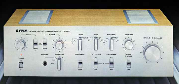
The Yamaha CA-1000 is an attractive, well-engineered and packaged integrated
stereo preamplifier-power amplifier combination. The front panel is horizontally
grained, clear anodized aluminum with all metal knobs. Construction, although
complex, appears to be very solid with PC boards used throughout. Extensive
use is made of shielding with critical circuits completely enclosed in metal.
Heat sinking and ventilation appear to be more than adequate. All in all, a
very nice looking unit.

Fig. 1-Back panel of the Yamaha CA-1000. Fig. 2-Interior of the CA-1000.

Fig. 3-Simplified block diagram.

Fig. 4-Simplified circuit of CA-1000 phono preamp.
= = = =
MANUFACTURER'S SPECIFICATIONS
Power Output: 70 watts/chan., 8 ohms, 20 Hz to 20 kHz, both chan. driven, Class B operation; 15 watts/chan., similar conditions but Class A operation.
THD: Less than 0.1 percent, Class B; Less than 0.05 percent, Class A.
IM: Less than 0.1 percent, Class A or Bandwidth: to 50 kHz, Class B; 5 Hz to 100 kHz, Class A.
Damping Factor: 70 at 1 kHz.
Frequency Response: 10 Hz to 50 kHz, +0.5 dB,-1 dB, 1 watt output.
Separation: 50 dB.
Hum and Noise: Phono 1 & 2, Greater than 80 dB; MIC, 70 dB; Tuner, AUX, Tape PB, 90 dB. Input Sensitivity: Phono 1 & 2, 3 mV; MIC, 2.5 mV; Tuner, Tape PB, 120 mV.
Tone Control Range: Bass, ±15 dB at 50 Hz; Treble, ±10 dB at 10 kHz.
Filters: -3 dB at 20 or 70 Hz, 12 dB per octave;-3 dB at 6 or 12 kHz, 6 dB per octave.
Dimensions: 17 1/4 in. W X 12 3/4 in. D X 5 3/4 in. H. Weight: 34.2 lbs.
Price: $600.00.
= = = =
Circuit Description
This unit has two features that are unusual and one in particular that is rare to say the least! The first is an extra low-level stage ahead of the normal phono preamp for low-output moving-coil pickups, and the other is a switch that changes the mode of operation of the power amplifier between the usual Class AB and Class A. It is a handy feature to have the built-in moving-coil pre-preamp as it appears that more high quality, low-output moving-coil pickups are coming on the market.
Class-A transistor power amps are rare because of their high power dissipation relative to their power output. This class of operation, however, has the advantage of complete freedom from low-level crossover distortion as the collector currents are continuous over the full signal cycle in each of the output devices. This reviewer has had a few 20-40 watt/ chan. Class-A transistor power amps to listen to in the past. Generally, this type of amplifier, when compared to Class AB units, tends to sound more neutral, less irritating, and larger and more dynamic than their power rating would indicate.
The CA-1000 has six amplifier blocks per channel; moving coil pre-preamp, mike preamp, phono preamp, tone-control amp, filter amp, and power amp. The tone-control amp, filter amp, and power amp are always in use for any input. When using the phono mode, the phono preamp is in use with the possibility of using the moving-coil (MC) pre-preamp ahead of the phono preamp to bring the output of moving-coil pickups up to normal phono input levels. The mike preamp is used only when the mike function is selected. Since the tone-control amplifier is always in the circuit, the preamplifier output amplifier section has two cascaded amplifiers in use compared to one in the usual preamp output amplifier configuration with the tone controls switched out. See Fig. 3.
The MC pre-preamp is a two-stage circuit utilizing a common base stage followed by a common emitter stage. Overall negative feedback is applied around the circuit to set the gain to about 20/1 with the low source impedances (1-5 ohms) that moving-coil cartridges present.
The mike preamp is a conventional two common emitter stage circuit using negative feedback for controlled gain and low distortion.
Yamaha's phono preamp circuit is very different from most in that it uses a combination of field effect (FETs) and bipolar transistors. A total of six active devices are used per channel.
See Fig. 4 for a simplified circuit. The FETs, Q1 and Q2, are connected in a series push-pull arrangement that Yamaha calls a SRPP (shunt-regulated push-pull) circuit. A positive going signal at the gate of Q1 turns it on harder, causing the drain voltage to decrease toward ground. The resulting increased current, which has to flow through R1 in order to get through Q1 to ground, causes a greater bias voltage for Q2 (gate becomes relatively more negative in respect to the source) and thus turns it off, aiding the negative-going signal at the drain of Q1. A negative-going signal at the input causes the opposite circuit reaction. The net result of this stage is that it tends to cancel even order harmonic distortion and provides a large drive capability to the following stages. Input random noise of FETs for first stage use can be very good and is for this circuit. The rest of the amplifier consists of a common emitter stage, with a high value of collector load resistor for large voltage gain, followed by an emitter-follower that drives a complementary output emitter-follower. A frequency-selective feedback network from the output to Q1's source gives the necessary RIAA equalization. Input signal acceptance is very high due to the relatively low 1-kHz gain (32 dB) and high supply voltage for the output stages of the circuit.
As can be seen in Fig. 5, the tone-control amp is the first amplifier in the preamp output section. It is a three transistor circuit with two common emitter stages separated by an emitter-follower. Tone-control action is somewhat unusual in that it balances frequency-dependent output attenuation against feedback-caused boost. Changing the position of the control pot wipers changes this balance resulting in a boost or cut characteristic. With the controls switched to out, the amplifier is still in the signal chain, but the reactive elements are switched out.
The filter amp provides most of the gain in the output amplifier section and has a circuit configuration like the tone control amp. Active 12 dB/octave low-cut filtering is accomplished by a passive two section RC network connected at the input, with the first shunt resistor fed from the first stage emitter, instead of being returned to ground. The output of the filter amplifier feeds a 20-dB voltage divider. The mute switch, which is convenient for reducing volume when the telephone rings, connects the outgoing signal to the top of this divider or the attenuated output for 0 or-20 dB relative attenuation.
The output impedance of this divider is about 2 Kilohms in either position of the mute switch and is used as a series resistance for the 6-dB/ octave hi-cut filters. Cutoff frequencies are changed by switching two different capacitors to ground.
The output of the hi-cut filter feeds the coupler switch which either connects the preamp output to the power amp input or allows a separate input to the power amp.
In the power amplifier, the input stage is a differential amp fed from a constant current source. This is followed by a second differential amp with one transistor acting as a pre-driver for the output stage. This transistor has a boot-strapped collector load and swings the full supply voltage. The output stage is a complementary Darlington connected emitter-follower with a voltage gain of slightly less than one. Output stage protection is of the VI type where output current and voltage are sensed and used to clamp the drive to the output stage when dissipation is excessive. The change from Class AB to A operation, in addition to reducing the supply voltage to the output stage, also increases the idling current from 50 mA to one amp by switching in a different bias-adjust pot.
This unit has a time-delay turn-on circuit that opens the speaker lines with a relay for 4-5 seconds to prevent turn-on thumps. This circuit also functions as a speaker protection device as the relay opens whenever any appreciable d.c. voltage appears at either of the power amp outputs.
The power supply consists of a large power transformer, two 18000/65 filter capacitors for the power amp out stages, and a ±50V bipolar voltage regulator. This regulator powers all of the preamplifier section with +50 volt (suitably decoupled as required) and the input and pre-driver stages of the power amplifiers. Part of the Class AB-A switch changes taps on the secondary of the power transformer to lower the output stage supply voltage for Class A operation. This supply voltage is ±20 V for Class A and ±50 V for Class AB.
Listening Tests
In order to be as objective as possible, listening tests are normally conducted before the equipment is measured. The CA-1000 was first listened to as a preamplifier only. The test setup permitted the phono preamp, with signal taken at tape output and followed by a dual 25K volume control, to be compared to the sound of the overall preamp at the preamp's main output. The phono preamp was found to be clean and free of edgyness but not quite as well defined as some other solid-state circuits. With the rest of the preamp switched in, the sound was perceptibly less defined. Switching the tone controls in and out made no perceptible difference. Next, the power amplifier was compared to some other solid state amplifiers and found to be very clean and transparent. It was a surprise to find so little difference between class A and Class AB operation, and Class AB was slightly preferred. Sound of the overall integrated unit was clean and quite satisfactory.
All of the controls performed their intended function with no race of clicks, pops, or noise. Pickups used for these tests were Supex SG-900 and Shure V-15 III.

Fig. 5-Phono RIAA EQ error, tone-control characteristics, and preamp output-amplifier
response. Note compression of frequency scale for preamp output-amp response.

Fig. 6-Phono preamp distortion versus phono preamp output.
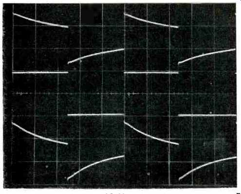
Fig. 7-Phono preamp 40-Hz square wave response, 5 mS/cm. Top is Hi-Z load,
0.5V/cm; middle, input to pre equalizer, 1V/em; bottom, 10K load, 0.5 V/cm.

Fig. 8-Phono preamp 1and 10-kHz square wave response, 204S/cm, with display
adjusted for input/output amplitude coincidence. Input to pre-equalizer is
1V/cm. Top, 10 kHz input and output, 20µS/cm; bottom, 1 kHz input and output,
200 µS/cm.

Fig. 9-Tone-control characteristics for 250and 5-kHz turnovers; loudness
contours, and low- and high-cut filter characteristics.
Measurements
Phono preamp: The gain of the phono preamp at 1 kHz measured 40X or 32 dB, which is somewhat lower than the usual 40 dB. Input noise over a 20-20 kHz bandwidth was 2.2 and 2.7 µV (-73 and-71.5 dB) in the left and right channels. These readings were dominated by 60 Hz components. With the measurement bandwidth set to 400-20 kHz, the input noise improved to 0.47 and 0.45 µV (-86.5 and-86.8 dB) The MC pre-preamp, when fed from a 1-ohm source, added an additional 26 dB of gain when switched in. Input noise of both channels of the pre-preamp measured 0.4 µV over a 20-20 kHz bandwidth and was dominated by low frequency random noise.
With a measurement bandwidth of 400-20 kHz, the input noise was 0.2 µV. Taking an input signal of 200 µV, which is typical of the Supex cartridge at 3.54 cm/sec, a signal-to-noise ratio of 60 dB would result. This noise level is felt to be quiet enough so that it would be buried by record surface noise and thus be inaudible.
RIAA equalization error for a non-inductive source is shown in Fig. 5. Further work has been done to determine the effects of different cartridge inductances on the RIAA equalization of phono preamps. A new test has been devised that lumps the effect of possible non-resistive input impedance and interaction of cartridge inductance on the feedback loop of the preamp under test. A representative example of low and high inductance pickups are used for the test which compares the response of the preamp under test to an ideal circuit that is free of the above effects. The CA-1000 phono preamp was found to have negligible deviation from ideal with the low inductance cartridge and a mild high frequency rolloff with a high inductance type of about-0.7 dB at 15 kHz and-2 dB at 20 kHz. If this preamp when using a high inductance pickup were compared to one that was flat or up in the high end on this new test, an audible difference would probably occur due to this effect alone.
This reviewer measures distortion and square-wave response of phono preamps by feeding the test signal through an inverse RIAA network or pre-equalizer and then into the phono input. Distortion data is shown in Fig. 6 for standard 60 and 7 kHz IM, 20 kHz THD, and 1 kHz difference tone distortion for equal amplitude 10 and 11 kHz input signals. All of these distortions are exceptionally low for this circuit.
Square-wave response for input frequencies of 40, 1 kHz, and 10 kHz are shown in Figs. 7 and 8. Figure 7 shows the effect on low-frequency phase shift, as evidenced by square-wave tilt, of loading the phono preamp output with a 10K load. A few tape recorders have an input impedance this low and could cause what this reviewer feels is excessive low frequency phase shift. High frequency bandwidth for the 10 kHz square wave is limited to about 50 kHz by limiting the rise time of the transition to 7 µS. Figure 8 has the output waveforms overlayed with the inputs for ease of comparison.
Phono-preamp crosstalk was measured on a pre-equalized basis and was found to be down more than 70 dB from 20 to 3 kHz, and rose to-54 dB at 20 kHz. This is very good for this test. Phono overload with frequency and output, along with equivalent input, were:
= = = =
Frequency - Output - Input
20 - 13.5Vrms - 34mVrms
100 14.0 77.5
1 kHz 14.0 350
10 K 14.0 1700
20 K 11.0 2800
= = = =
Preamp Output--Amplifier: The voltage gain of the output amplifier section with volume control at maximum and loudness control at position zero (no compensation) was 6.8X or 16.7 dB. This, when combined with the phono gain of 32 dB, gives a total preamp gain at 1 kHz of 49.7 dB, compared to 60 for most preamps, to accept the wide dynamic range of this pre amp. Tone-control and frequency response curves are shown in Fig. 5. Tone-control curves for other turnovers, loudness contours, and high- and low-filter responses are shown in Fig. 9.
The tone-control curves are for .front panel markings of -5 through +5. The controls click like switches but are continuously variable pots with detent mechanisms. Distribution of amounts of boost or cut for each position is not uniform and, particularly for positions 2 and 3, are rather close together.
This may be different for various samples of the CA-1000. Loudness control curves are given for panel positions of 0, 2, 4, 6, 8, 9, and 10. Frequency response doesn't change much until positions 3 and 4 are reached. Filter cutoff slopes are 12 dB/ octave for the low-cut filters and 6 dB/ octave for the high cut.
Square-wave responses are shown in Figs. 12 and 13 for frequencies of 20 and 20 kHz. For some reason that remains obscure, the very low end response is better with the bass control switched in.
IM distortion of the output section was less than 0.03 percent for an output of 2.5 V or below with a 10K load. Harmonic distortion for the same conditions was less than 0.02 percent from 20-20 kHz.
Crosstalk between channels was measured by feeding one channel of AUX 1 and shorting the other channel input. Volume control was at maximum, and all filters and tone controls were switched to the OUT positions. Crosstalk was down more than 80 dB between 50 and 500 Hz rising to-75 dB at 20 Hz and-55 dB at 20 kHz.

Fig. 10-Preamplifier output-amplifier 20-Hz square-wave response, 10 mS/cm.
Top is tone control out, 1V/cm; middle input, 0.2 V/cm; and bottom tone control
in, 1V/cm f

Fig. 11-Preamplifier output-amplifier 20-kHz square wave response, 10 µS/cm.
Top is tone control out, 1V/cm; middle input, 0.2 V/cm; and bottom tone control
in, 1V/cm.

Fig. 12-THD and IM distortion versus power input.

Fig. 13-Frequency response (1 watt) and THD frequency and power, both for
the power amp.
Output amplifier noise was measured over a 20-20 kHz band and with the volume control at the worse case position (generally about 6 dB down from maximum). This noise was slightly more with the tone controls switched in and was 22 µV for the left and 24 µV for the right which is satisfactorily low.
Power Amplifier: The voltage gain of the power amp was 31.6X or 30 dB which is 4 dB over the usual 26 dB. IM distortion and 1 kHz THD are shown in Fig. 14. Distortion was plotted for the left channel in every case as this channel was the higher of the two. Right-channel distortion was about 50-70 percent of the left. It can be seen that the distortion in general is lower with Class A operation. The dashed curves in Fig. 14 are the sum of the 5th and 7th harmonics in the IM residue and are measured using a special comb filter that allows the sum or any combination of harmonics to be measured up the 7th.
The amount of 5th and 7th are felt to have some correlation to irritation and graininess in power amplifiers. This circuit is remarkably free of higher order odd harmonics even in the
Class AB mode of operation where one would expect to see more of this kind of distortion, especially at low levels. Harmonic distortion vs. frequency for three power levels along with wide band frequency response at one watt are shown in Fig. 15. Square wave performance at 50 and 10 kHz is shown in Fig. 16. The middle trace shows the effect of a 2µF capacitor across the 8-ohm load. The aberation is dominated by the output buffing RL network used in this and most amplifiers with no VI limiting taking place at this 10-V peak-to-peak output level.

Fig. 14-Power amplifier 50-Hz and 10-kHz square-wave response. Top is 10
kHz, 8 ohm load, 5 V/cm, 20 µS/cm; middle is same as top with addition of
2 µF across 8 ohms; bottom, 50 Hz, 8 ohms, 5 V/cm, 5 mS/cm.
Damping factor was measured by injecting a known current into the output terminals of the amplifier and measuring the resultant voltage drop. Output impedance is calculated as this voltage divided by the known current. The damping factor was 80 from 20-1 kHz and decreased to 15 at 20 kHz, still satisfactorily high.
Output hum and noise at idle in a 20-20 kHz bandwidth for the Class AB mode was 77 and 94 µV in the left channels which is 109.7 and 108 dB below 70 W, 8 ohms. Hum and noise in the Class A mode was 278 and 325 µ V in left and right channels and was mostly line harmonics.
Clipping power into 4 and 16 ohms was 123 W and 58.1 W for Class AB and 27.6 W and 9.9 W for Class A. Power at 8 ohms was 92 watts, Class AB; 18 watts, Class A.
In conclusion, the CA-1000 is a well-made, excellent performing unit that is a pleasure to look at and use and should appeal to many who are interested in an integrated amplifier of this type.
(Source: Audio magazine, Sept. 1974; Bascom H. King)
= = = =