.---------
In addition to boosting bass, the circuit acts as an infrasonic filter, relieving your system of the task of reproducing inaudible garbage.
------------
Unless your speakers are too big for your living room, your audio system probably does not reproduce the lowest bass octave. To keep cost and size reasonable, design engineers have eliminated the lowest octave; hence, very few speakers respond below about 40 Hz and few bookshelf systems go even as low as 50 Hz. This is unfortunate, for the lowest note on a standard piano is 27.5 Hz, which would be a more desirable goal for low-end reproduction.
The lowest recorded tone that can be called music is 16 Hz, which is produced only by large organs and specially built, 96-key Bosendorfer pianos. Such sounds are felt rather than heard. There are only a handful of recordings with these notes, but most symphonic and jazz recordings contain information between 27 and 40 Hz, if it hasn't been lost in the recording process. With the advent of the digital Compact Disc, such losses are ceasing to be a problem.
The choices open to those who want more bass are not always practical; large, expensive speakers might do the job, as might a separate sub-woofer, if one had enough space and money.
Electronics offers another alternative. As Fig. 1 shows, an acoustic-suspension speaker behaves like a second-order, high-pass filter, its bass response sloping off at 6 dB/octave below a frequency that varies with the speaker. If the signal is first fed through an electrical filter network, it is possible to make the speaker respond like a fourth-order filter (which is how a tuned-port loudspeaker behaves). The net result is an extension of bass response by about an octave. I have measured the parameters of many speakers, and have found that "Q" (a measure of response "peakiness" near cutoff) averages about 0.9 for units that aspire to high fidelity, ranging between 0.7 (British speakers) and 1.1. I have designed a filter with a 0 that will extend the bass response with any such speaker. Only the resonant frequency of the filter need be adjusted to match the unit at hand.
There are some disadvantages to this method. It will only work with acoustic-suspension designs. Maxi mum sound pressure level will not be as great as might be obtained by other techniques. In theory, distortion will be greater because of the greater cone excursion. However, this hasn't proven audible in practice, due perhaps to masking effects (in the case of harmonic distortion) and the fact that the increase in Doppler and IM distortion, though measurable, may not be significant. The most serious disadvantage is the need for extra power, roughly double that required without the filter. Unless your amp's power is marginal to begin with, this won't present an obstacle if you don't habitually crank up the bass and volume controls. In any case, you will want to be sure that your speakers are properly protected. A 2-ampere, fast-acting fuse will be adequate; do not use a larger size unless your speaker manufacturer specifically recommends it, and under no circum stances use slow-blow fuses.
On the plus side, this circuit also acts as an infrasonic filter, and so relieves your amp and speakers of the task of reproducing inaudible garbage that can overload them.
Figure 2 is a schematic of one channel and the power supply. IC1B is a buffer that isolates the filter from loading effects of the input source impedance. Resistors R101 and R102 form a voltage divider to set the overall circuit gain to unity-the filter does introduce some gain, for which this compensates. IC1A is the heart of the filter.
Capacitors C101 and C102, in con junction with R103 through R106, set the frequency, which is variable between 20 and 50 Hz. Resistors R107 and R108 determine the filter Q. The input is directly coupled, but the output uses a blocking capacitor, C103, to isolate the amplifier from the d.c. offset voltage produced by IC1A. If your amp has a blocking capacitor at its input, C103 may be omitted. Almost any standard compensated op-amp will give satisfactory results in this circuit, but FET input devices such as the LF353 or TL072 are superior. Dual devices (two ICs in one package) were used. I suggest mounting the ICs in sockets rather than soldering them.
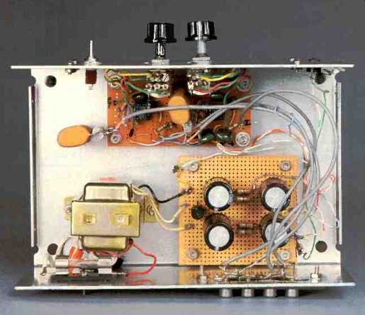
The circuit was constructed on a dual IC board, Radio Shack #276-159.
You may find this somewhat cramped; a larger p.c. board such as Radio Shack's #276-168 may be easier to work with. For the most part, layout is not critical, but keep the following points in mind: All leads to the negative IC inputs should be as short as possible, to minimize noise. Decoupling capacitors C5 and C6 (shown on the power-supply schematic) should be mounted on the same board as the opamps in order to minimize noise pickup from the power supply. Put these caps as close to the op-amps as is reason ably possible. The transformer should not be too close to the op-amps.
Shielded cable was used for the signal leads; twisted pairs of wires will also work, though placement is then more critical for minimum noise. Purists who feel electrolytics degrade signals may want to bypass C103 with a 1,000-pF silver mica cap, or eliminate it altogether. (The latter isn't recommended unless you have some alternate means of blocking d.c. input to your amp.) Potentiometer R105-R106, which controls the frequency, is a dual-ganged, preferably log-taper type; however, audio-taper pots, which are much easier to find, work reasonably well. You may calibrate this control by measuring the resistance of one pot, and calculating the frequency thus:
F = 159/ 0.047 x (68 + R)
where R is the measured value of R105 in kilohms. If you find the scale too cramped at the upper end, rewire the pot, reversing the connection that shorts the wiper.
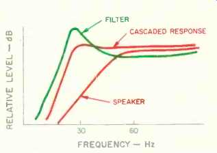
Fig. 1--Response curves for an acoustic-suspension speaker, the filter
described in this article, and their combined response.
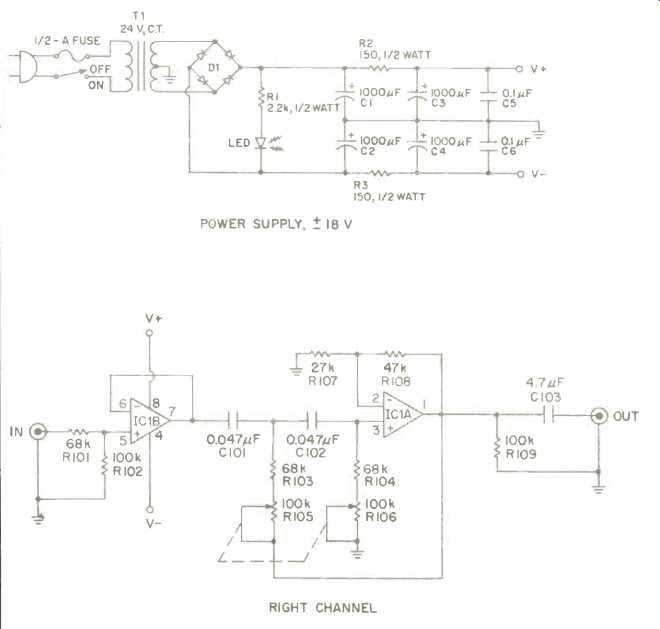
Fig. 2--Schematic diagram of the filter. Left channel is identical to
the right channel shown, but uses IC2 and part numbers above 200.
Before you connect power, double check your wiring for errors. The filter can be placed between your preamp and amplifier or in a signal processor or tape monitor loop. You may want to add extra jacks and a DPDT switch to maintain tape-monitor facilities. The setting for frequency is not terribly critical, though for greatest accuracy it should be approximately one-half the speaker's resonant frequency. If loading problems at the output make the circuit oscillate, a 100-ohm resistor in series with C103 (or in C103's place, if it's eliminated) will solve the problem.
You can measure your speakers' resonant frequency if you have a signal generator. Put a 2-watt resistor, between 500 ohms and 1 kilohm, in series with your speaker, and feed the output of the signal generator through your amp. Measure the voltage across the speaker; it will reach a maximum at the resonant frequency.
The speakers that I use have a resonant frequency of 58 Hz, and the manufacturer states the cutoff frequency to be 48 Hz. A setting of 28 Hz gives me the most accurate bass response, reasonably smooth down to 27 Hz-pretty good for an 8-inch speaker. A setting of slightly below 30 Hz will be about right for most 8-inch speakers. Larger speakers are more variable, and experimentation will be required. The most accurate setting doesn't affect the sound, except when deep bass is truly present. Most FM stations roll off their bass below 40 Hz, so this source is not an accurate test. Prerecorded cassettes and most cassette decks give up at this point also. Records, and of course CDs, will allow you to deter mine the most accurate setting. Organ music and jazz piano will come alive when the filter is properly adjusted. Of course, there is nothing sacred about accuracy. Setting the controls to 50 Hz will give a pleasing bottom to rock and popular music.
Eight-inch speakers can thus reproduce all but the lowest half-octave. If the filter is used with 10- or 12-inch speakers that have a long cone excursion, they will reproduce accurate bass right down to 20 Hz, assuming their present low end is around 40 Hz.
With adequate amplifier power, this filter will give you a truly compact subwoofer, electronically.
PARTS LIST
NOTES: All resistors are 1/4-watt, 5%, unless otherwise noted. Right-channel parts are series 100; left channel, series 200.
- R1--22-kilohm, 1/2-watt, 10% resistor.
- R2, R3--150-ohm, 1/2-watt, 10% resistors.
- R101, R103, R104, R201, R203, R204--68-kilohm resistors.
- R102, R109, R202, R209--100-kil ohm resistors.
- R107, R207--27-kilohm resistors.
- R108, R208--47-kilohm resistors.
- R105-R106, R205-R206--100-kil-ohm, dual-gang potentiometers, log or audio taper (see text).
- C1 through C4--1,000-µF, 25-V electrolytic capacitors.
- C5, C6-- 0.1-uF, plastic-film (Mylar) capacitors. (Mount near IC1 and IC2.)
- C101, C102, C201, C202--0.047-µF, plastic-film capacitors (5% preferred, 10% acceptable).
- C103, C203--4.7-µF (or greater), nonpolarized capacitors (plastic-film preferred, electrolytic accept able).
- IC1, IC2--TL072 dual op-amps, or similar (see text).
- D1--50-PIV, 1-amp bridge rectifier.
- T1--24-V, center-tapped transformer.
- Miscellaneous--LED, fuse, switch (optional), wire, phono jacks, line cord and plug, p.c. board, and sockets for ICs.
========================
(adapted from Audio magazine, Aug. 1985)
= = = =
Also see:
The Certified Bass for the Certifiable (Jan. 1990)
Build a High-Performance Noise Reducer (Feb. 1985)
Link |