by H. W. HELLYER
DESIGN PHILOSOPHY dictates which sort of tape drive shall be used-direct motor, belt, or idler. Each has certain advantages and some drawbacks. For speed exactitude, and precise control, directly driven capstan and reel carriers will be chosen; the obvious drawback is its high cost.
The choice between belts and idlers is not so simple. Quite often we find the maker has compromised, using both types of drive in the same machine, performing different functions.
Belts, or bands, may be rubber, composition or fabricised rubber, and can be round, triangular, or rectangular in cross-section. The most important criterion is evenness of cross-section, with elasticity following a close second.
Round-section belts will more often be used with a large-diameter motor pulley. It is more difficult to maintain constant diameter of a round belt, and under tension the belt `flattens' at contact points, so angle-section belts are used with smaller-diameter motor pulleys having shaped flanges in which the belt rides snugly. The other alternative is a flat belt on a wide running surface, and fabricised flat belts which accept variations of tension for function change (play/fast wind/reverse) are favored by some designers. Where flat belts are used, the general tendency is to employ a slipping-belt drive for take-up rather than a slipping-clutch or gravity take-up, and vertically mounted machines may therefore have tensioned flat belts. Idlers, jockey pulleys, puck wheels, or intermediate wheels, called variously (though not strictly correctly)
by all these names, are used to couple the drive from the motor to the flywheel and to the reel carriers. Many different systems are employed, each with its own peculiarity.
Most idlers are rubber-tired, and the type of rubber used has to be chosen carefully. As well as having good elastic properties, it must have a good coefficient of friction, the minimum of self-heating, and high abrasion resistance-properties which do not always go hand-in-hand. Because maximum tension must be achieved to reduce slip, pressure on the idler will be high. This tends to stress bearings, and makes the initial contact of idler and drive (or driven) surface vulnerable to irregular forces. For optimum transmission of drive power, systems are designed to be self-adjusting, the idler being held in contact with the driving surface by spring pressure.
Idler wheels lend themselves to designs which need reversal of driving direction, such as for the rewind operation, and to speed changes which can be effected by a stepped driving pulley. They are useful when the spacing between drive wheel and driven surface has to be varied, or is large.
Because the friction wheel is spring-loaded to make contact, some retardation is inevitable, and this has to be allowed for in design. The wedge angle for optimum conditions has been determined empirically to lie between 35 and 40 deg. for optimum drive with least slip. Figure 1 (A) shows a simple spring-loaded drive wheel, and in Figure 1 (B) we can see the design principles for an intermediate wheel. The wedge angle of 35 deg. is determined by experience, and wheel diameters should have specific relationships.
The diameter of an idler wheel should, in theory, make no difference to the speed of the driven surface.
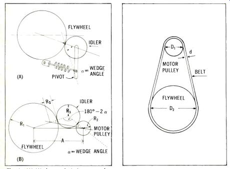
Fig. 1-(A) Wedge angle important for correct transmission of torque. (B)
Distances and wedge angles can be calculated when diameters of motor pulley
and flywheel are known.
Fig. 2-Speed of a flywheel is not in inverse ratio to the diameters of motor pulley and flywheel, but has to take into account the thickness of the belt.
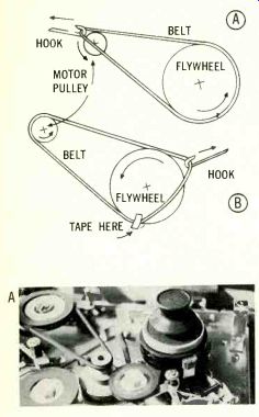
------------Fig. 3--(A) A simpler method of loading a new belt where surfaces are accessible. The hook is used to maintain tension. (B) Where other parts of the mechanism overlay the pulleys, a better method is to put the belt over the smaller diameter, secure at the rotational entry point, and use the hook to feed the belt over the larger diameter while turning gently.
(A) Combination belt-and-pulley drive is used on many machines, as in this example-Sony TC-250.
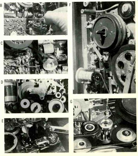
(B) Small drive belts such as this one in the Uher 4000-L
can be handled with a pair of tweezers, but extreme care is needed, and
sharp edges of tools should be protected with adhesive tape.
(B) Flat wide belts may suffer from impregnation; small particles of metal from pulleys become embedded, imparting a surface polish. This example is a Sony CV-2000 video tape recorder.
(D) This assembly from a West German pocket portable uses a number of plastic pulleys with thin rubber tires. Check for binding bearings and out-of-line spindles.
(E) Japanese Standard portable has edge drive from motor to flywheel and rim-drive from flywheel to take-up.
(F) Examples of the wide, thin take-up idler on a loose bracket which is liable to misalignment, and the smaller soft-tired auxiliary wheel at right. Philips 3548.
(G) Ramped idler for speed change.
-----
This is dependent on the ratio of the motor to flywheel diameters, in the case of direct drive. Interposing an idler reverses the direction of rotation, but should have no effect on the speed. In practice, small changes in diameter upset the tensioning, the wedge angle, and the calculated amount of slippage and can cause a slowing down or irregularity.
Belt Faults
Many of the factors governing regular running with idler-wheel drive also apply to belt-drive systems. Small variations in belt thickness can have a large effect on tape speed. The thickness of flat belts is more easily controlled than the diameter of round ones. Importance of exact belt diameter or thickness is illustrated with reference to Fig. 2.
If the motor pulley were geared to the driven pulley, the speed reduction at the capstan would be in inverse proportion to the diameters, i.e. n1/n2 =D2 D1. Taking a practical example, a belt-driven flywheel 95.5 mm in diameter is required to rotate at 300 r.p.m. The available motor rotates at 2900 r.p.m. If a thickness of belt is 1 mm this must be added to each diameter in the above equation, giving So the effective drive at the motor has a diameter of 10mm.
Suppose there is a variation of 10 per cent in belt thickness over its length. The resulting speed variation will be 0.1 x 100/10 or 1 percent.
The running frequency of the belt is only a few cycles and speed variations of such a low frequency can hardly be equalized by the centrifugal mass, so wow will be heard from pitch variations.
--------
thus n, D,+d n, D,+d D,= n.(D,+d)
n, 300x96.5_1 2900
= 9mm.
-------------
If a flat belt is used, closer limits can be gained, and by hardening, then grinding the flat surfaces, deviations of less than 0.5 per cent can be achieved. From the foregoing it also appears that the larger the diameter of the motor pulley the less the effect of these deviations will be, but this has practical limits. This would require a slow-running motor, or a centrifugal mass (flywheel) of large diameter, or the addition of an intermediate drive wheel. We are back where we began.
Speed changing with belt drive can present special problems. The usual method is to feed the belt from one diameter to another on a common motor pulley. A fork drive may be used, or a tongue on the pulley.
One advantage of belt drive on simpler machines is the ability to filter out minor variations inherent in the system. Motor hum vibrations at 60 Hz can be reduced considerably by using a belt of sufficient elasticity to form an absorption circuit. This is very useful when a motor with an outer rotating cage (small diameter pulley) is employed in conjunction with a flywheel. The small diameter is dictated by the high rotational speed. Flywheel rotation should be as high as is practicable, and the short-term speed variations can be formidable unless belt elasticity is carefully chosen to filter them out. It follows that any hardening of the belt or loss of elasticity due to temperature and humidity changes will also affect drive regularity.
Neglect is the prime culprit-as has already been emphasized in this series of articles.. Belts that are left in one position tend to harden and form to a shape, with flattened portions at the contact sections. The cure is a regular use of the machine, but if the condition has already set in, some remedy may be possible by heating and running the belt.
Best method of rejuvenating a formed rubber belt is to let it stand for a while in hot water, dry it, powder with French chalk or talcum, clean off surplus talcum to prevent it mixing with lubricants, and "run the belt in" for a reasonable period.
Mention of lubricants brings us to the prime enemy of belts-and indeed of any rubber or composition drive surfaces, including idler-wheel tires.
This is oil or grease. Over-enthusiastic lubrication has caused more erratic tape drive than any other single fault.
Oil tends to spin off rotating bearings in a fine film; grease can have a capillary action when heated, creeping up to idler surfaces. Always oil sparingly, and wipe any surplus from spindles before fitting belts or idler wheels.
Diluted alcohol is the best cleaning agent, but even this has to be used with care on some composition materials, which can soften by its solvent action.
Refitting drive belts can face us with some problems. One or two tricks of the trade can make the job easier.
The first thing to remember is sequence.
Unless you know the machine so well that dismantling deck parts becomes habitual, keep a note of the order in which parts are removed.
Lay the parts in a logical sequence, ready for re-assembly.. Make drawings where necessary, and always include some sort of datum: 'deck front', `head-plate', 'motor mounting', and so on. If it helps, number the operations on your guide drawing. For some of us, one map is worth a wealth of words.
When fitting a belt over two drive surfaces, with the belt under tension, some difficulty may be encountered in getting the belt to sit snugly on the larger diameter surface. Best method of attacking this problem is to loop the belt over the small surface, hold in place by stretching slightly, then feed it around the larger diameter slowly, turning in the direction it wants to go.
It is wise, when rotating flywheels or motors, to move these in their ‘natural’ direction of rotation.
Where a narrow flange is used, and the new belt is reluctant to stay in place, even with the tension and rotation method of fitting, one or two pieces of adhesive tape pressed lightly over the belt at the entry point will give a starter. After this, the wheel can be rotated and an outward tension maintained as it is fed into place. One useful aid for this job is that family heirloom, the button-hook.
If you can't find a button-hook, which is hardly likely today, fashion a stiff piece of wire into a nearly-closed loop and hook it over the belt.
Use this, as in Fig. 3, to hold the belt away from the entry point of the flywheel, just enough to maintain tension while the wheel is rotated.
Although the use of pliers on rubber or composition belts is to be deprecated, it is occasionally necessary to employ a pair of tweezers to lift an otherwise inaccessible belt. Use the type with a flat blade and trust the clamping action to do the work.
If this is not sufficient, you'll simply have to resort to the hook.. But always avoid anything sharp. Protect the blade tips with a collar of rubber sleeving, or even a layer of cellophane tape.
After using any sort of adhesive tape on or near a belt, clean both the belt and any surface it contacts with alcohol. Before switching on, rotate the assembly by hand, ensuring that the movement of the motor pulley produces the correct result. After a tedious job of assembly, nothing is more annoying than a spilled belt.
Where flat belts run over tensioning pulleys, it is essential that these shall have their spindles at right angles to the belt run. Fitting tensioned belts is often easier when the tension is partly applied, so it helps to remove the strong spring and fit an auxiliary spring to give temporary weak pressure where needed--or, in extremis, to wedge the pulley bracket in place.
Belts that rely on forks or tongues to reposition them for speed changing should not be shifted unless they are turning. The prime cause of belt spill with some machines is speed changing when at rest.
Conversely, idler wheels that are ramped to step on different pulley diameters for speed changing should only be moved axially when in the neutral position. There are exceptions, but these are usually soft-tired idlers with lightly-sprung guide brackets. In these cases, attention to the spring pressure is needed: some slippage may be required, over-drive can be as bad as under-tensioning.
Prime cause of poor pulley drive is a binding bearing caused by an influx of dirt or a hardening of lubrication.
Dismantle, taking care to note washer sequence, and clean thoroughly.
Again, resort to the thumbnail sketch if several washers are used.. Lay the washers in order of removal, ready for refitting. These may be of dissimilar material, to suit bearing hardness. Reassembly in the same order is vital to smooth operation.
Clean out the bearing barrel of the pulley and lubricate very lightly after reassembly. Clean the periphery of the idler with alcohol, looking particularly for embedded particles. Aluminum flywheels are particularly prone to shed surface flakes, so clean not only the pulley but the surface it drives.
Brass surfaces can polish rubber tires, producing slippage because of the hardened driving edge. If the pulley is not too far gone (hardened by constant temperature changes and polishing), treatment as for hardened belts may do the job. Scrape the edge of the pulley gently with a sharp blade, avoiding nicks and notches, to renew the surface, then treat again with alcohol before refitting.
Pulleys, idlers, puck wheels, and intermediate wheels that have been left in engagement for any length of time will present a formed surface, and cause a `knock'. Listen as the machine runs; gauge the rotational speed from the frequency of the knock, and identify the offending idler. If it is in the early stage of deformation, heat treatment and cleaning may improve matters, but when in doubt, fit a new idler. For the cost of a few cents, future worries may be saved.
------------------
(Audio magazine, 11/1969)
Also see:
ABZ's of Stereo FM--Modern Switching-Circuit Decoder
= = = =